5EIB0 Computation II
- Area: Computer Engineering
- Topics: Digital Logic · Finite State Machines and Automata · Hardware Description Languages and FPGAs · Instruction Set Architecture · Processor Datapath and Pipelining · Caches and Memory Hierarchy · Processes, Threads and Synchronization · Parallel Computing
- Related courses: Operating Systems - 2INC0 · Computation Modeling - 5XIE0 · Electronics II - 5ECC0
- Resit notes: Cache (resit) - 5EIB0 · Compiler (resit) - 5EIB0 · Computation I Recap (resit) - 5EIB0 · FPGA (resit) - 5EIB0 · Finite State Machine (resit) - 5EIB0 · Floating Point (resit) - 5EIB0 · GPU (resit) - 5EIB0 · Instructions (resit) - 5EIB0 · Overview (resit) - 5EIB0 · Parallel Computing (resit) - 5EIB0 · Processor Design (resit) - 5EIB0
Goals
The Hitchhiker’s Guide to the CPU Hardware - YouTube
Summary
Computer architecture:
- multi-cycle processors (hardware-performance trade off)
- pipelining (hazards and forwarding)
- advanced memory hierarchies
- instruction set design (RISC, CISC, SIMD, custom instructions)
- architecture classification
Hardware design: - Boolean logic
- Finite State Machines (FSMs)
- Verilog HDL
- custom hardware / special function units
- logic synthesis
- MIPS design (Verilog)
Embedded systems: - embedded system design concepts
- real-time systems
- interfacing with sensors and actuators i/o
Learning Goals
- synthesize a pipelined computer architecture using a hardware description language (HDL);
- develop custom hardware using synthesis tools;
- integrate computer systems within a larger embedded control system;
- develop systems that meet the real-time constraints of embedded applications.
General Goals
In depth:
- computer architecture (including memory hierarchy)
- Processor Design and Implementation of RISC processors (all the details about 5-stage pipelined MIPS)
- Verilog (HW) design
Introductory:
- Operating systems
- multi core processors
- GPUs (Graphic Processing Units) and Vector processors
Learning Outcomes
• Working knowledge of the properties and function of modern computer architectures and be able to compare them.
• Quantitatively analyze the performance of modern computer architectures, including their memory subsystem.
• Working knowledge of the basic functionality of Operating Systems – Basic knowledge of implementing a Linux driver
• Working knowledge of the different ways of building parallel / multiprocessors
• Working knowledge of combinational and synchronous hardware and the ability to practically apply this knowledge to create synthesisable hardware designs in Verilog
• Design an FSM and code it in Verilog
• Design a pipelined RISC type of processor in Verilog
• Optimize execution of a specific application by adapting: – the application program – processor hardware
Labs
Lab is split in two parts:
– Verilog: Hardware design using Finite State Machines (FSMs)
– mMIPS: Computer Architecture and Hardware Design
Theory
• Book “Comp. Org and Design” (6th ed.), study sections:
• Appendix B1-5, B7-8, B10 (important for labs)
• 2.1-2.14 • 4.1-4.13
• 3.6-3.8 • 5.1-5.4, 5.7-5.8, 5.10
• 6.1-6.6, 6.9, 6.12-6.13
• Operating Systems: “Introduction to Operating Systems”, chapters 1-4 (available on OnCourse)
Combinational Verilog & Sequential Circuits, Verilog, FSMs
Logic
- Signals can be asserted (true or 1) or deasserted (false or 0).
- Gates: eg: AND, OR ; Universal Gates: eg: NOR, NAND
- half adder, full adder
- synthesis: HDL to circuit
- Register transfer level (RTL): type of behavioral modeling for synthesis
Logic Blocks
- Combinational Logic: No memory; output based only on current inputs. (AND, OR etc…)
- Sequential Logic: Contains memory; output depends on inputs and stored state. (registers / flip-flops, register files, RAM, etc…)
Combinational Logic
Topic: Digital Logic
Decoders
- Converts
input to max outputs. (could also be etc..) - Only one output is true based on the input’s binary value.
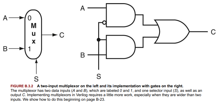
Multiplexors (MUX)
- Selects output from multiple inputs based on a control signal. (selector value)
- Can be expanded beyond two inputs, requiring a decoder for selection.
Two-Level Logic and PLAs
- Logic functions can be simplified to two levels of logic (AND, OR) with possible NOT operations.
- Sum of Products (SOP) and Product of Sums (POS) are two canonical forms.
- Programmable Logic Arrays (PLAs) implement SOP forms efficiently. (minterms first stage of PLA, product terms).
ROMs and PROMs
- Read-Only Memory (ROM) encodes logic functions as memory contents, fixed at manufacture or programmable (PROM).
- ROMs are fully decoded, containing output for every input combination, differing from the partial decoding of PLAs which are more efficient.
Don’t Cares
- Situations where the output value does not affect the operation, allowing for optimization in logic function implementation.
- Output Don’t Cares: Output value is irrelevant for some input combinations.
- Input Don’t Cares: Certain inputs do not affect the output.
Arrays of Logic Elements
- Operations on data often apply to entire words (e.g., 32 bits), requiring arrays of logic elements.
- Buses are treated as single logical signals but consist of multiple data lines.
- Multiplexors can be arrayed to select between buses of multiple bit widths.
Example Applications
- Decoders in addressing memory or selecting circuit paths.
- Multiplexors in data path selection or control signal routing.
- PLAs for implementing complex logic functions with minimized gate count.
- ROMs for storing fixed logic functions, especially useful in initialization or configuration settings.
HDL Verilog
Topic: Hardware Description Languages and FPGAs
ref: https://sutherland-hdl.com/pdfs/verilog_2001_ref_guide.pdf
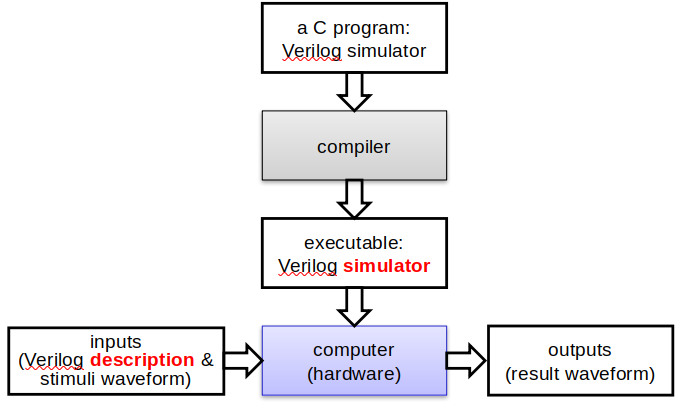
short:https://www.youtube.com/watch?v=2IReMT_zjK8
long:https://www.youtube.com/watch?v=PJGvZSlsLKs
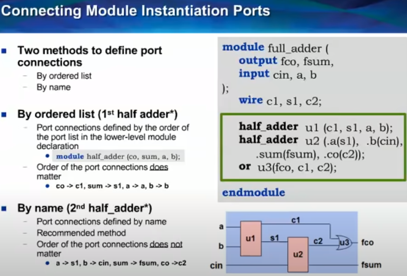
Verilog: Allows both behavioral(input/output responses) and structural(interconnected low level components) descriptions of digital systems.
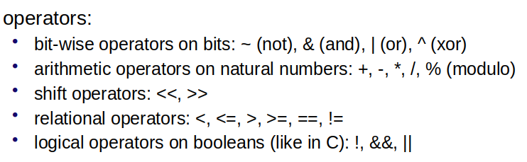
| is an operator, “or” is a separator
Key Concepts in Verilog
- Datatypes:
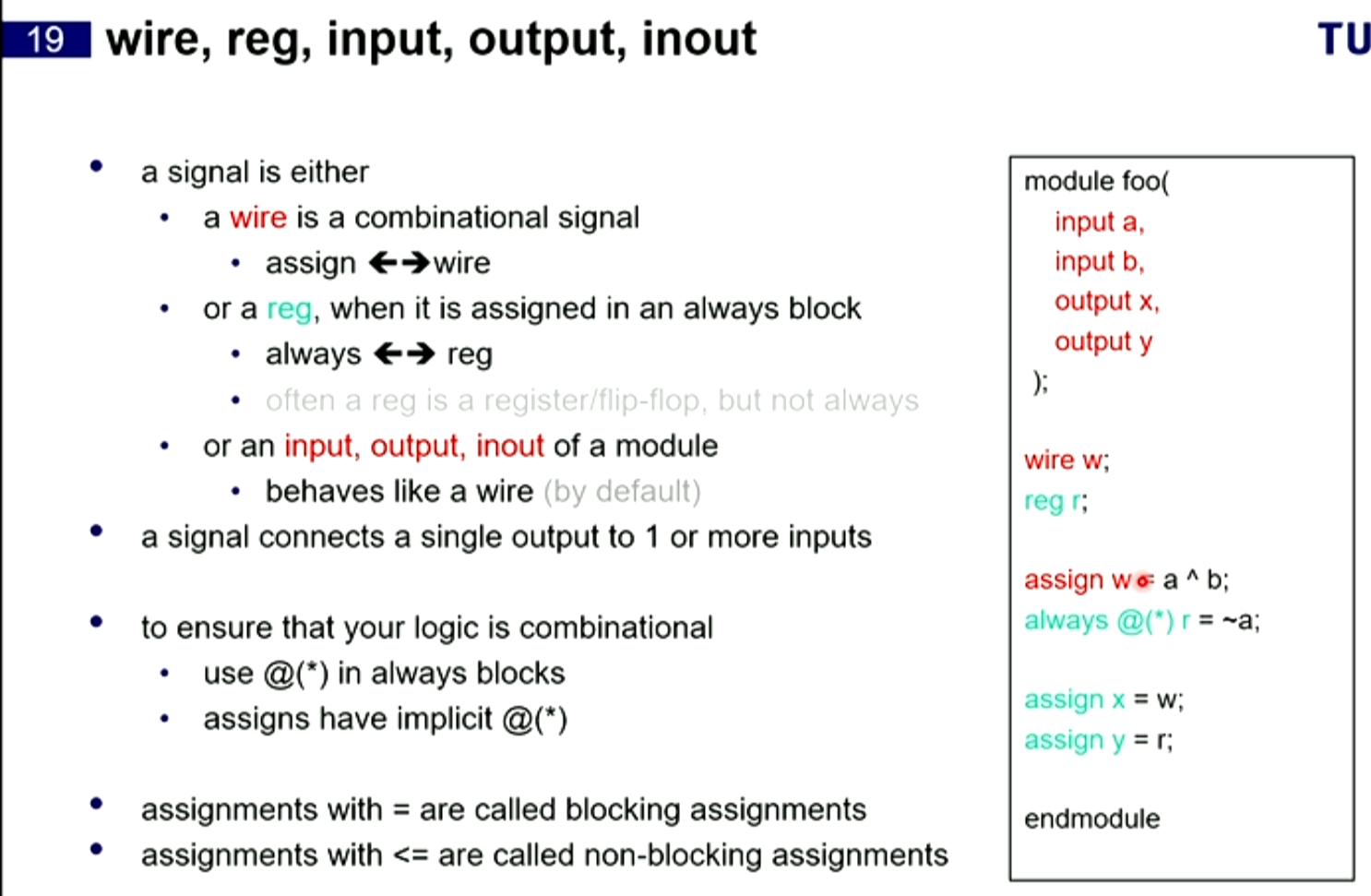
wire: Represents combinational signals.reg: Holds values that can vary over time, not necessarily physical registers.
- Operators: Includes arithmetic, logical, comparison, shift, and conditional operators, similar to C.
Verilog Modules
- Verilog programs are structured as modules, which can represent anything from logic gates to whole systems.
- Modules specify inputs, outputs, and contain:
initialconstructs for initializing variables.- Continuous assignments (
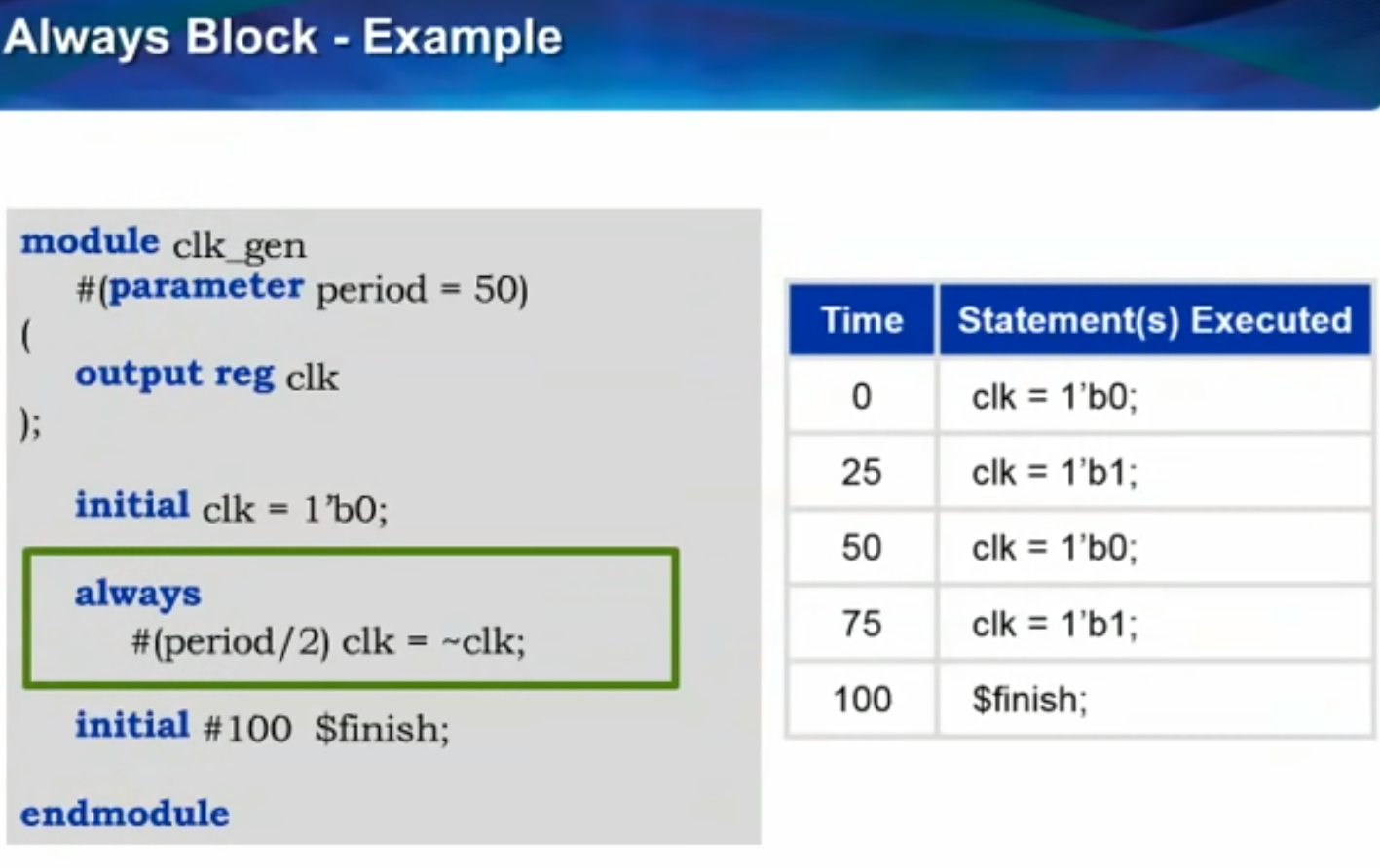
assign) for combinational logic. alwaysconstructs for sequential or combinational logic.- Instances of other modules.
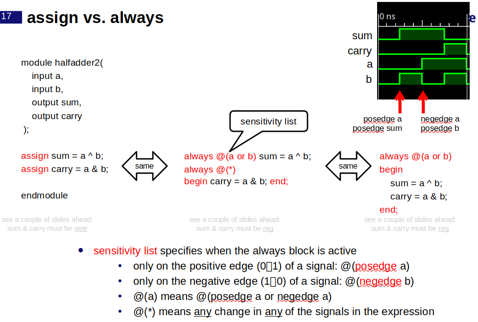
Combination Logic in Verilog
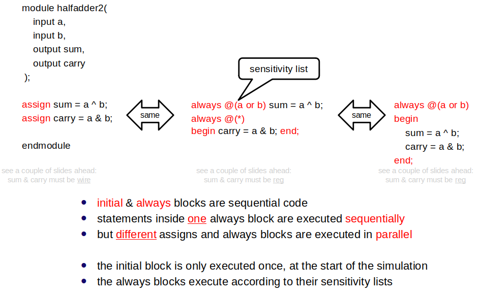
- Use
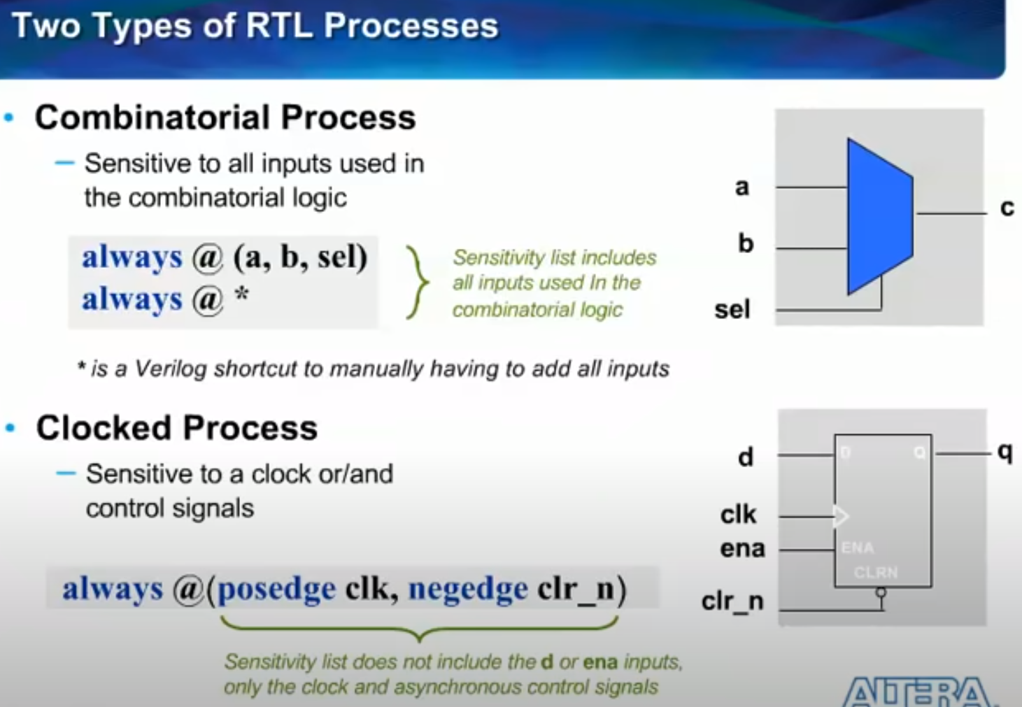
assignstatements for direct combinational logic definition. alwaysblocks can also define combinational logic, with careful attention to the sensitivity list and ensuring all paths assign values to the same set of bits.
Sequential Logic in Verilog
https://www.youtube.com/watch?v=11UAXr1ueIQ&t
https://www.youtube.com/watch?v=OE0fVERonm0
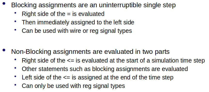
- Sequential logic is defined using
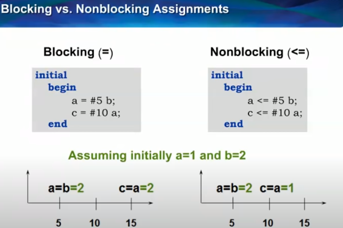
alwaysblocks. - Blocking (
=) and nonblocking (<=) assignments control the order of operations and synthesis of actual registers. - blocking: an assignment that completes before the execution of the next statement. (represents respected sequential execution use in combo cases)
- non-blocking: An assignment that continues after evaluating the right-hand side, assigning the left-hand side the value only after all right-hand sides are evaluated. (introduces parallelism)
Common Verilog Constructs
- Continuous assignments are straightforward for combinational logic.
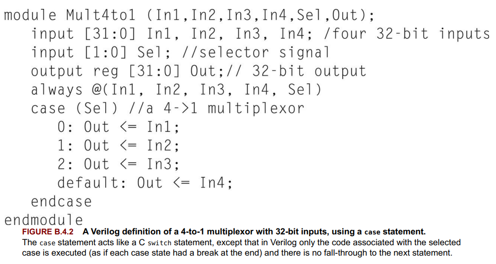
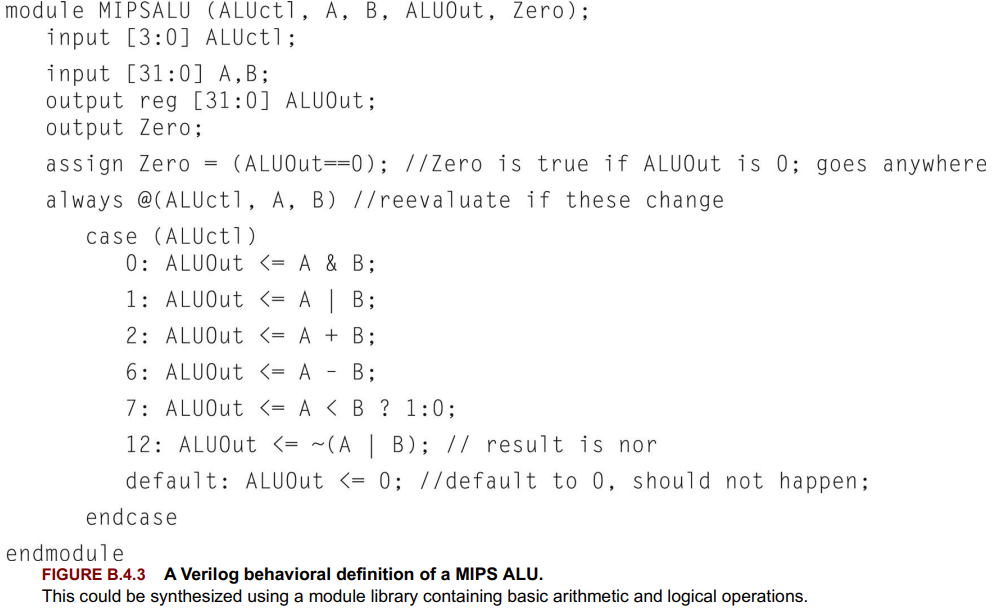
alwaysblocks offer more complexity and control, using Verilog control structures likeif,case, and loops.- Care is needed to ensure combinational logic does not unintentionally synthesize as sequential logic (e.g., latches).
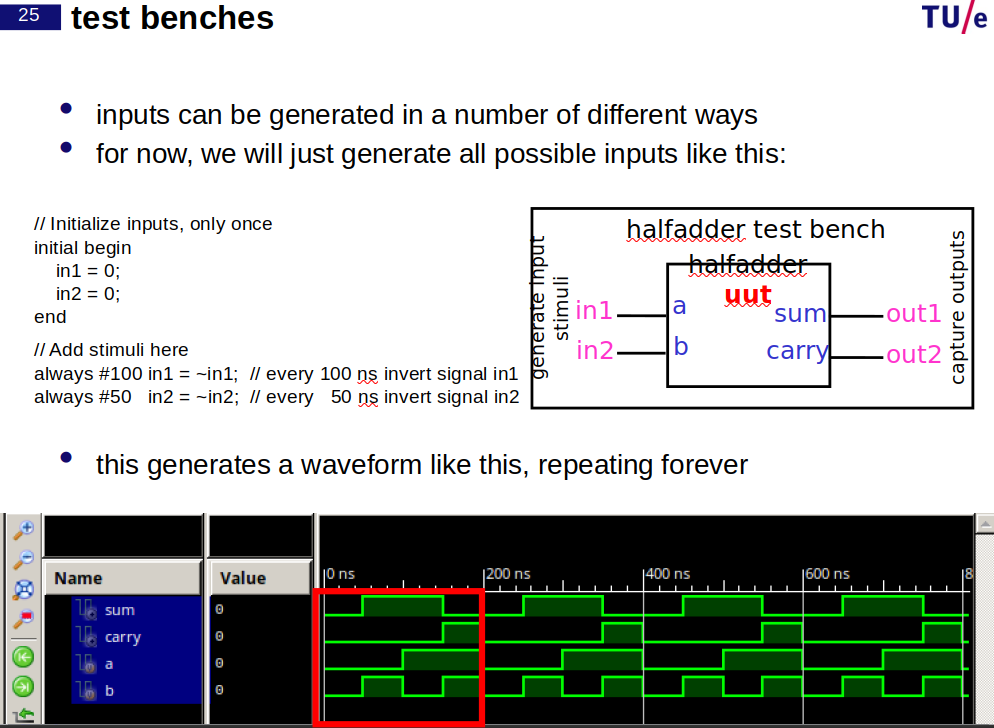
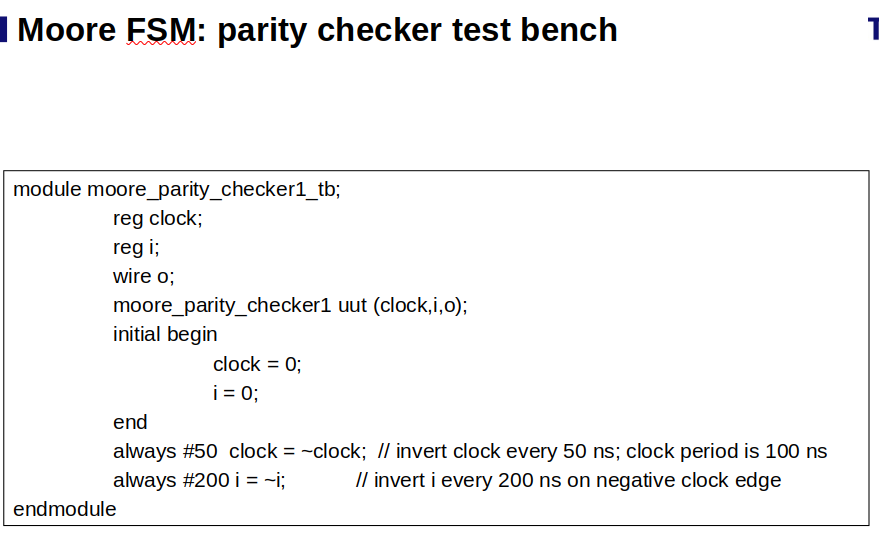
- a test bench supplies inputs (stimuli) to the unit under test (UUT, also known as device under test DUT) and listens to the outputs (results)
Best Practices
- Place all combinational logic in a continuous assignment or an always block.
- Ensure all inputs are in the sensitivity list of
alwaysblocks for combinational logic. - Ensure every path through an
alwaysblock assigns values to the same set of bits to avoid unintended sequential logic synthesis.
- Use
display to display values that have been assigned using nonblocking assignments. - always blocks are executed in no specific order we use non-blocking, if we use blocking then it will matter.
// combinational
module and_gate(
    input wire A, // Input A
    input wire B, // Input B
    output wire Y // Output Y
);
// AND gate logic
assign Y = A & B;
endmodule

// sequantial
module d_flip_flop(
    input wire D, // Data input
    input wire clk, // Clock input
    output reg Q // Output Q
);
// D flip-flop logic
always @(posedge clk) begin
    Q <= D;
end
endmodule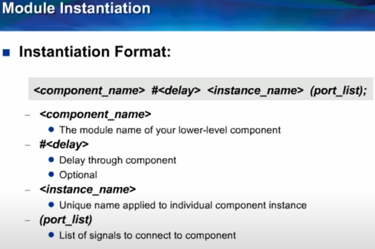
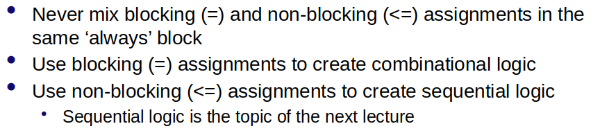
- Guideline #1: When modeling sequential logic, use nonblocking assignments.
- Guideline #2: When modeling latches, use nonblocking assignments.
- Guideline #3: When modeling combinational logic with an always block, use blocking assignments.
- Guideline #4: When modeling both sequential and combinational logic within the same always block, use nonblocking assignments.
- Guideline #5: Do not mix blocking and nonblocking assignments in the same always block.
- Guideline #6: Do not make assignments to the same variable from more than one always block.
- Guideline #7: Use $strobe to display values that have been assigned using nonblocking assignments. Guideline
- #8: Do not make assignments using #0 delays.
System Tasks and Functions
$display,$write,$monitor,$timeformatfor simulation output.- File I/O operations:
$fopen,$fclose,$fwrite, etc. - Type conversions, simulation control (
$finish,$stop).
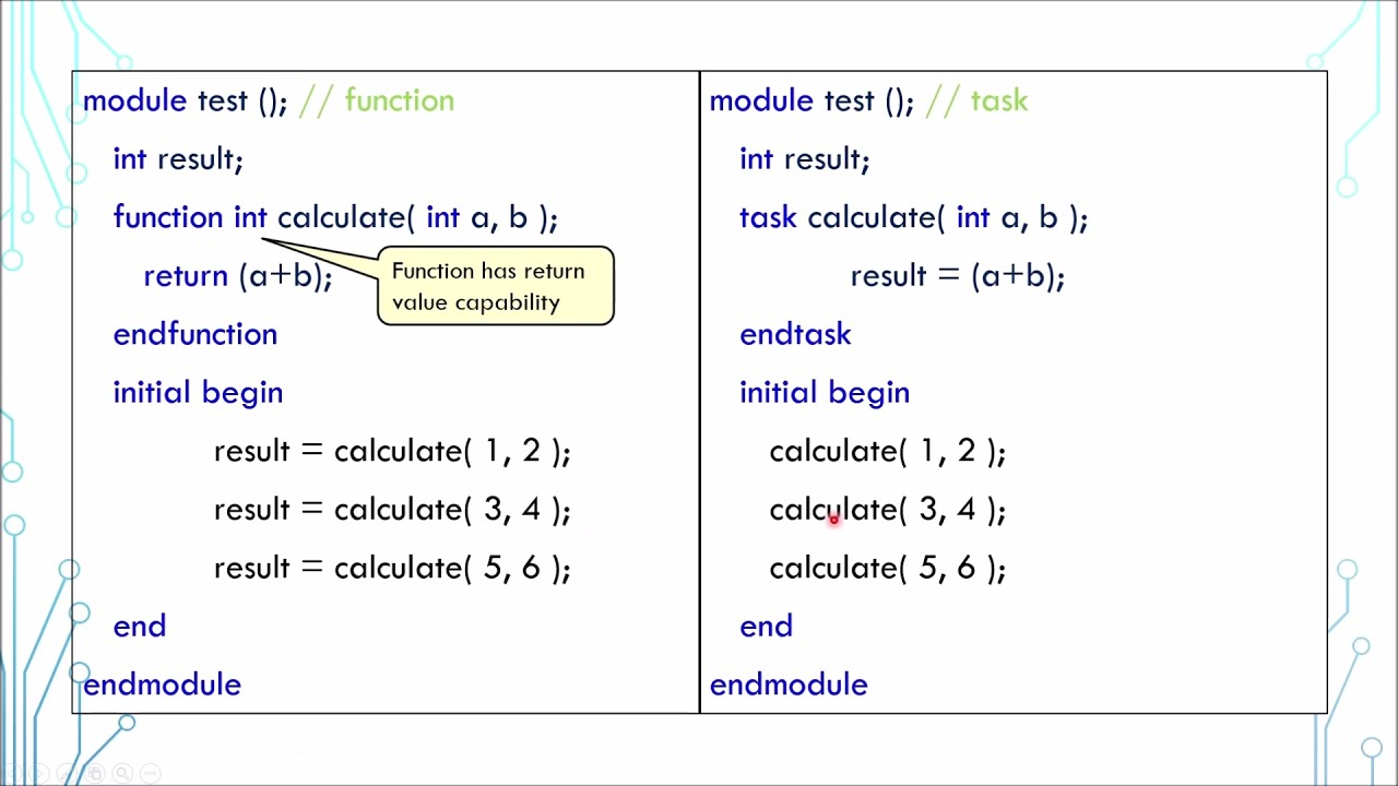
Tasks and Functions - Tasks for subroutines, functions for returning values.
automatickeyword for re-entrant tasks/functions.
Compiler Directivesdefine,include,ifdef/ifndef,timescalefor pre-processing.
Configurations and Library Mapping- Use
configfor specifying source code binding for modules/instances. - Library map files for mapping symbolic libraries to file locations.
Data Types - Nets for connections (wire, tri, supply0/1, etc.), variables for storage (reg, integer, real, etc.).
- Constants:
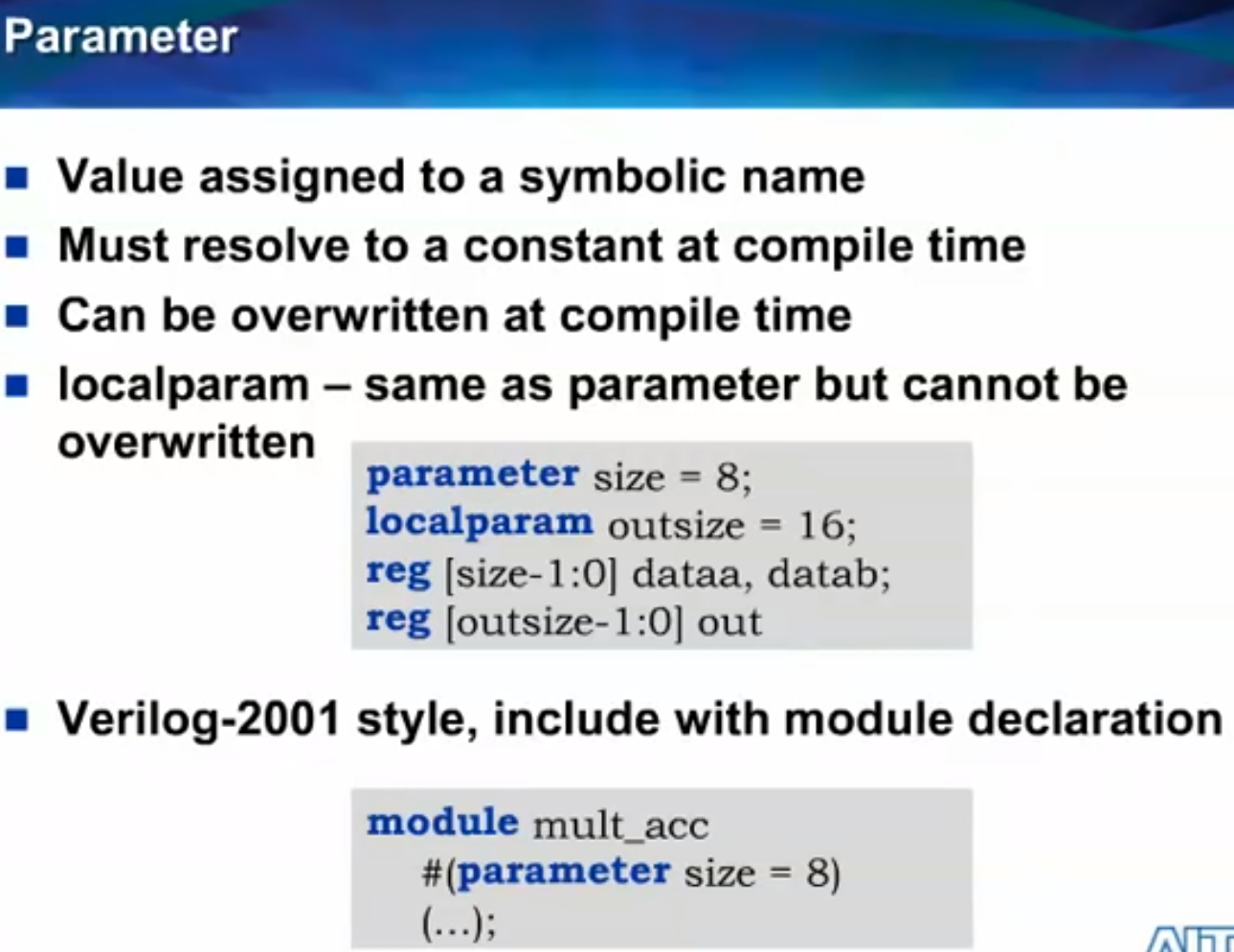
parameter,localparam,specparam. - Signed and unsigned types, arrays, initialization with declaration.
Arithmetic Logic Unit (ALU)
Topic: Digital Logic
Overview
- The ALU is the core component that performs arithmetic (addition, subtraction) and logical operations (AND, OR) in a computer.
- A 32-bit wide ALU can be constructed by connecting 32 1-bit ALUs.
1-Bit ALU Design
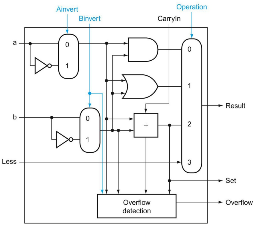
- Logical Operations: Directly mapped using (AND, OR gates, and a multiplexor and inverters) to select between AND or OR operations based on the control signal.
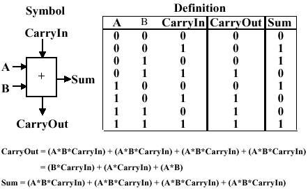
- Addition: Implemented using a full adder with two operand inputs, and a carry-in (CarryIn), and two outputs: sum and carry-out (CarryOut).
Constructing a 32-Bit ALU
- Ripple Carry Adder: Sequentially connects the carry-out of one bit to the carry-in of the next, creating a ripple effect for carries across all bits.
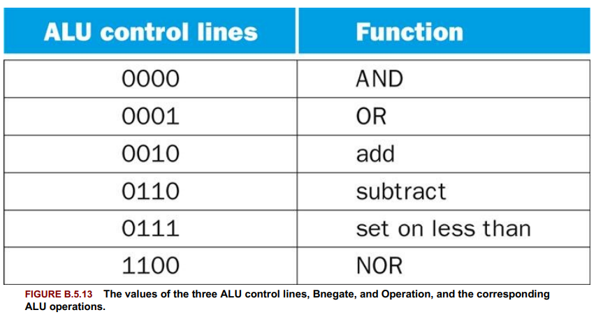
- Subtraction: Achieved by adding the negative of an operand, implemented by inverting each bit of one operand and adding a carry-in of 1 to the least significant bit. (two complement form) Binvert
- Support for NOR Function: Implemented by reusing hardware for AND and NOT operations, following DeMorgan’s theorem:
. Ainvert
Enhancements for MIPS Architecture
- Set on Less Than (slt): Expanded multiplexor to include an input for slt results, with special logic in the most significant bit to determine the negative result indicating
a < b. Set or Overflow - Zero Detection: To support conditional branches, hardware to detect if the result is zero was added.
- Control Signals: Simplified by combining CarryIn and Binvert into a single control line called Bnegate.
Clocks
https://www.youtube.com/watch?v=wx0NyUfpm48
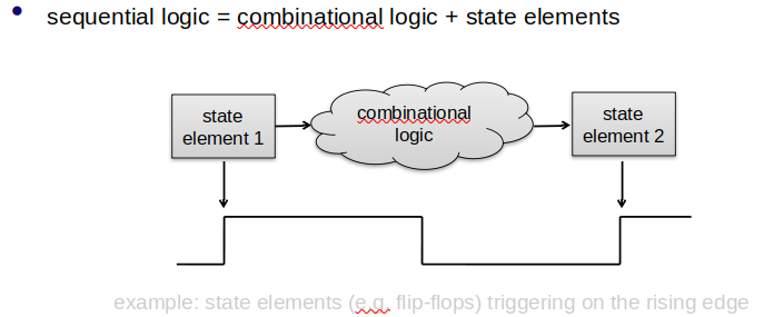
Edge-Triggered Clocking
- Definition: A clocking scheme where state changes occur at a clock edge (rising or falling).
- Purpose: Used in sequential logic to dictate when state elements (memory elements) should update.
State Elements and Synchronous Systems
- State Element: A component that stores state information, updating only at the active clock edge.
- Synchronous System: Utilizes clocks to ensure data signals are only read when stable, maintaining signal validity throughout the system.
Design Constraints
- The clock period must allow enough time for all signals within combinational logic blocks to stabilize before being sampled by the clock edge. This sets a minimum bound on the clock period for ensuring data validity.
Sequential Logic Design
- Involves state elements providing inputs to combinational logic blocks, whose outputs are then fed back into state elements. This cycle requires careful timing to ensure data sampled by the clock edge is valid.
Memory Elements: Flip-Flops, Latches, and Registers
Topic: Digital Logic
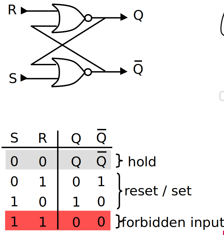
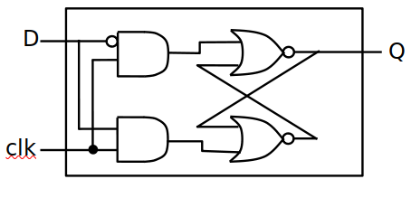
S-R Latch
- Built from cross-coupled NOR gates, storing state when neither S (Set) nor R (Reset) are asserted.
- Asserting S sets Q, asserting R resets Q. Asserting both S and R can lead to unpredictable behavior.
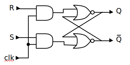
- gated S-R latch has CLK component: only works during clock : 1
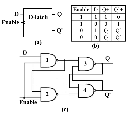
- D Latch : just a gated S-R latch with D=
=R
D Flip-Flops and Latches
-
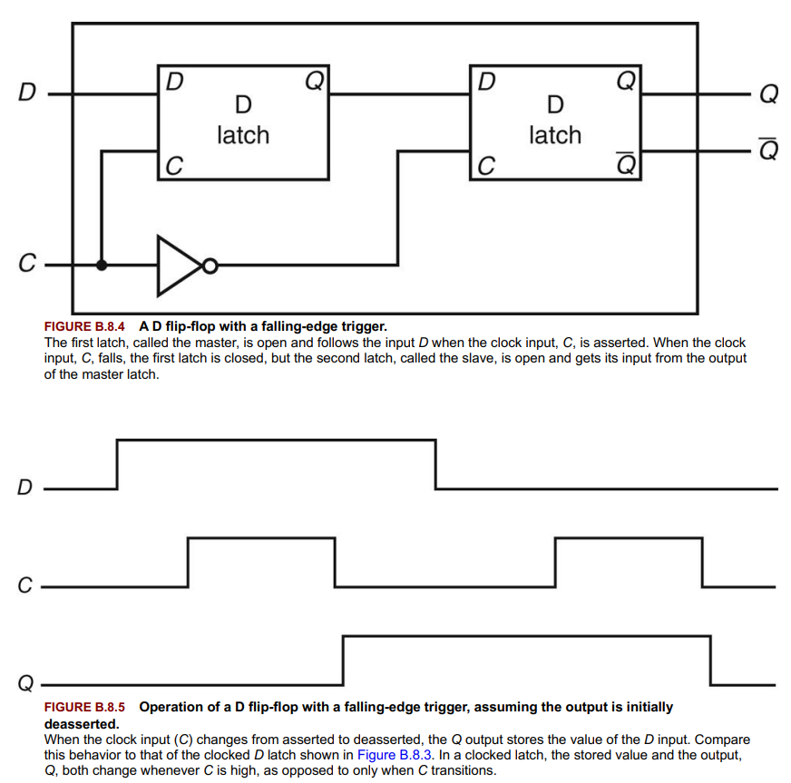
Flip-Flop: Outputs equal the stored state, changing only at clock edges, making them suitable for edge-triggered designs, not-transparent. (made from latches)
-
D-Flip-flop: https://www.youtube.com/watch?v=YW-_GkUguMM
-
-
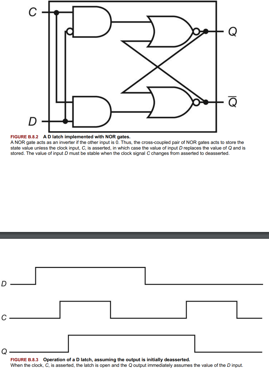
Latch: Outputs also equal the stored state but can change whenever inputs change with the clock asserted, making them transparent. (not preferred)
-
-
Edge-triggered registers are specified using
posedgeornegedgein the sensitivity list of analwaysblock. -
Flip-flops and latches are foundational for creating reliable sequential circuits.
-
Transparent state, changes to the input directly affect the output.
Setup and Hold Time
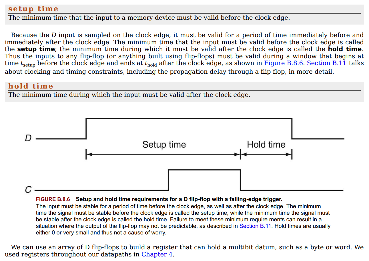
- Critical timing constraints for flip-flops ensuring D input validity before and after clock edges to prevent unpredictable outputs.
Register Files
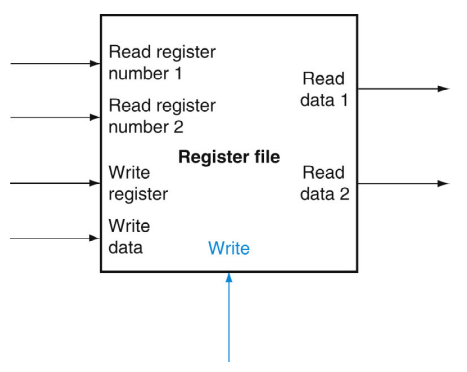
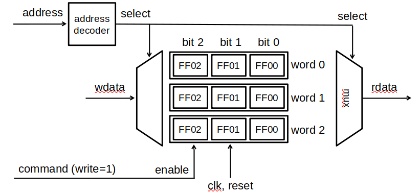
- Consist of multiple registers accessible by supplying a register number, implemented with decoders and an array of D flip-flops.
- Essential for datapath designs, allowing simultaneous reads and writes within a clock cycle.
- Registers are temporary storage locations inside the CPU that hold data and addresses.
Finite-State Machines
Topic: Finite State Machines and Automata
main: https://www.youtube.com/watch?v=kb-Ww8HaHuE
difference: https://www.youtube.com/watch?v=YiQxeuB56i0
Definition and Components
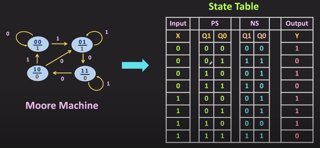
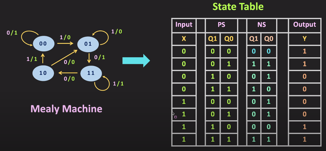
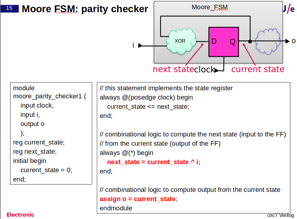
- Finite-State Machine (FSM): A sequential system characterized by a set of states, inputs, and outputs. It consists of a next-state function determining the future state based on current inputs and state, and an output function producing outputs from the current state and possibly inputs.
- States: Represent all possible values of the internal storage, with n bits of storage translating to
states. - Next-State Function: A combinational function that maps current state and inputs to the next state.
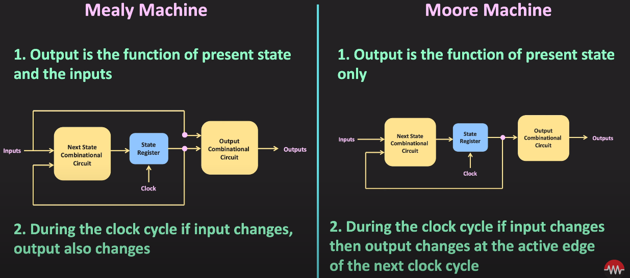
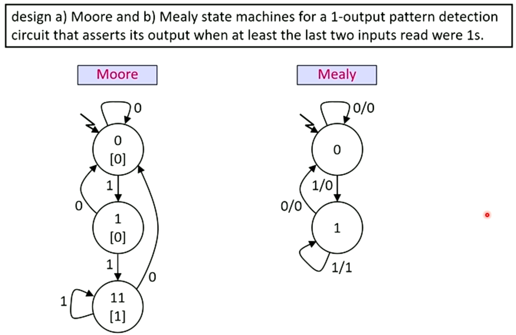
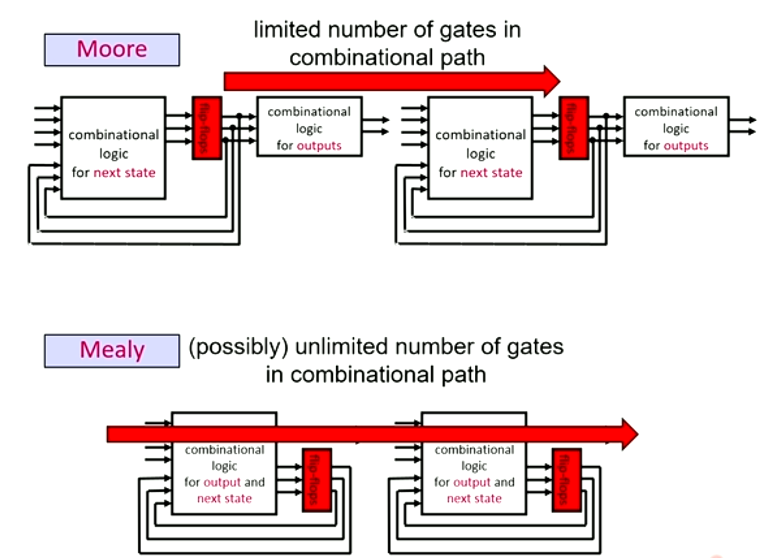
- Output Function: Generates outputs from the current state and inputs. **In Moore machines, it depends solely on the current state, whereas in Mealy machines, it can also depend on the inputs.
- Moore vs. Mealy Machines: Moore machines’ outputs depend only on the state, potentially making them faster but larger. Mealy machines’ outputs can depend on the state and inputs, possibly requiring fewer states but introducing complexity in design.
Synchronous State Machines
- Operate in sync with clock cycles, updating state elements only at clock edges, simplifying the explanation and design process. Needed for Mealy machine. Sine Moore already behaves that way.
Implementation
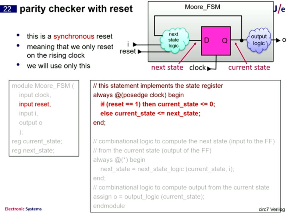
- Utilizes a state register for current state storage and combinational logic blocks for computing next-state and output functions.
- State assignment assigns numerical values to each state for implementation purposes.
- Combinational logic often realized using structured logic like Programmable Logic Arrays (PLAs), facilitating automatic optimization and implementation via CAD tools.
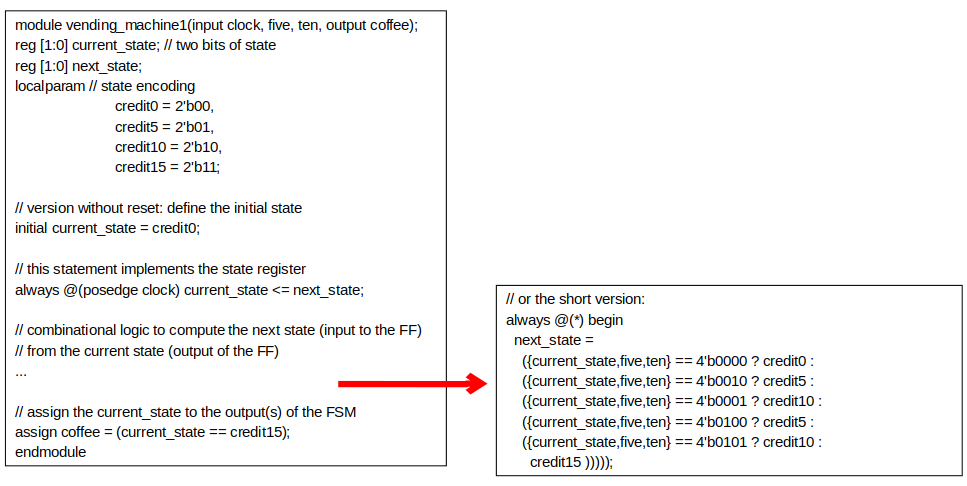
FSM Verilog
Topic: Hardware Description Languages and FPGAs
MIPS Recap, MIPS Pipelined
Topic: Instruction Set Architecture
Lecture
(lui) not really a load doesn’t load from data memory
branch instruction works in the following way:
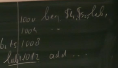
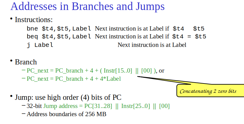
when a branch is triggered at (1000) due to the clock moving its already at (1004) so it only needs to move 2 instructions
adding 2 00s = 4 && Inst[15..0] offset
moving backwards:
If we denote PCbranch as 1000, we’re actually considering the effect from the position of 1004 because of the automatic increment. Therefore, to move from 1004 to 996, we need an offset that, when multiplied by 4 and added to 1004, equals 996.
Solving for the offset:
1004+(offset×4)=996
Subtract 1004 from both sides:
offset×4=996−1004
offset×4=−8
Therefore, the offset:
offset=−2
This is why the instruction field Instr[15..0] should be set to -2. The representation of -2 in a 16-bit field uses two’s complement notation, which is how negative numbers are encoded in binary.
j instruction for jump was structured weirdly as it glues 4 bits instead of adding: so there are limits to where it can jump
NEXT LECTURE:

The instruction names are misleading. Use addu for both signed and unsigned operands, if you do not want a trap on overflow.
Use add if you need a trap on overflow for some reason. Most languages do not want a trap on signed overflow, so add is rarely useful.
unsigned → used for addressing usually

pseudo blt
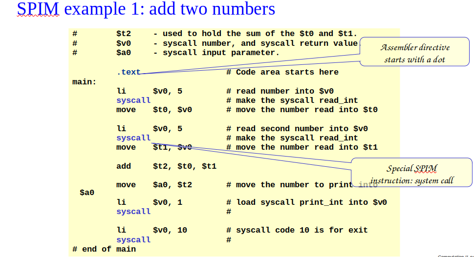
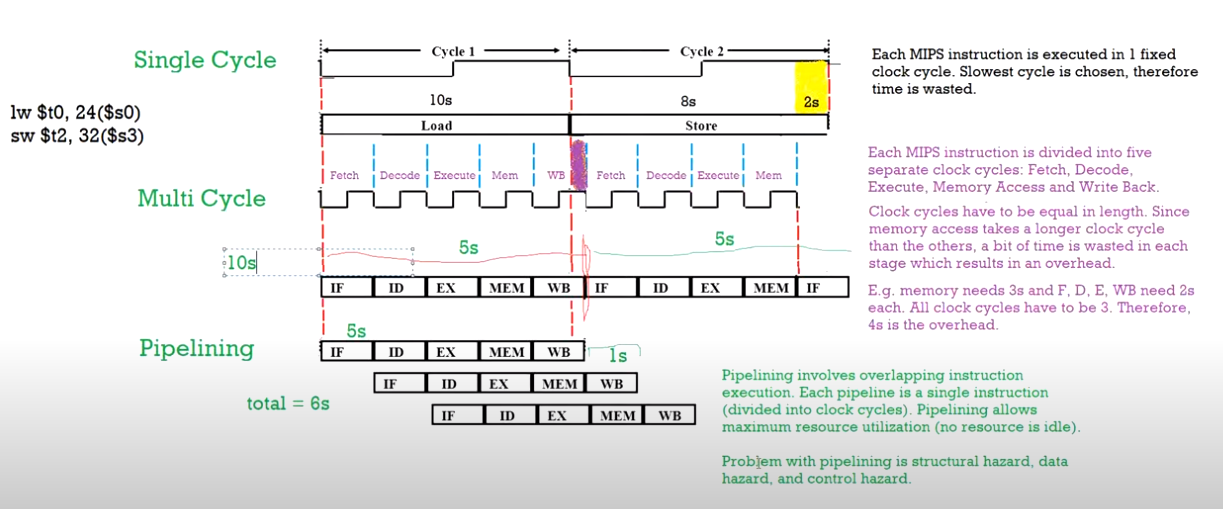
Type of MIPS Execution
Single Cycle, Multi Cycle, and Pipelining - YouTube
Ift201 MIPS Data Path Lecture - YouTube
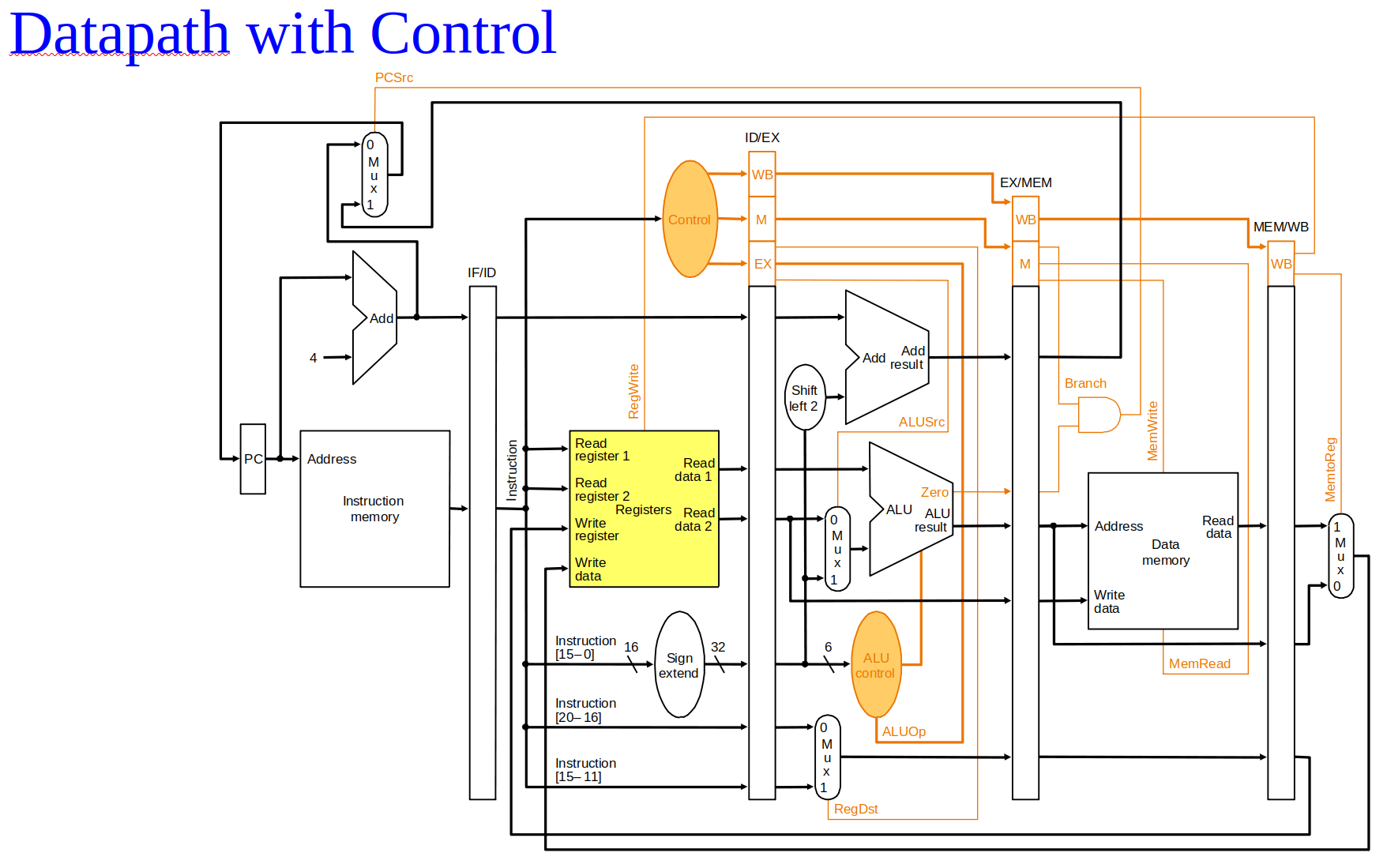
Pipeline control:
Instruction Fetch and PC Increment
Instruction Decode / Register Fetch
Execution
Memory Stage
Write Back
Introduction
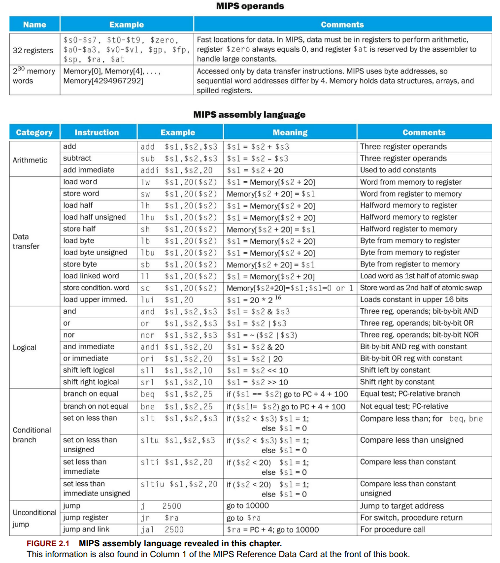
Operations of the Computer Hardware
- MIPS instruction format:
operation destination, source1, source2 - Example:
add a, b, c(addsbandc, stores the result ina)
Operands of the Computer Hardware
- MIPS registers: 32-bit registers, used as operands in instructions. (32 bits, 4 bytes word (or 2 bytes), 1 byte→8 bits)
- Design Principle 2: Smaller is faster, influencing register count for speed and simplicity.
- Register naming:
s1, … for C/Java variables; t1, … for temporary variables. - Memory vs. Registers: Arithmetic operations on registers; data transfer instructions (
lwfor load,swfor store) for memory access. - Addressing: Byte addressing with alignment restriction; word addresses must be multiples of 4.
- Load/store example:
lw $t0,32($s3)loads A[8] intot0,48( t0 into A[12] in memory. - Constant operands:
addi $s3,$s3,4adds 4 to $s3 directly, without loading from memory. - Why is the maximum value of an unsigned n-bit integer 2ⁿ-1 and not 2ⁿ?]
Signed and Unsigned Numbers
- Binary representation:
or (bit) is the basic unit; numbers represented in base - Unsigned numbers: Non-negative, range
to for -bit systems. - Two’s complement: Standard for representing signed numbers; leading
s for positive, s for negative. - Most significant bit (MSB): Indicates sign in two’s complement;
for positive, for negative. - Overflow: Occurs when result exceeds hardware representation capacity.
- Sign extension: Extends a number to a larger bit width by replicating the sign bit.
- Negation shortcut: Invert all bits and add
to negate a two’s complement number.
Representing Instructions in the Computer
Topic: Instruction Set Architecture
- Register mapping:
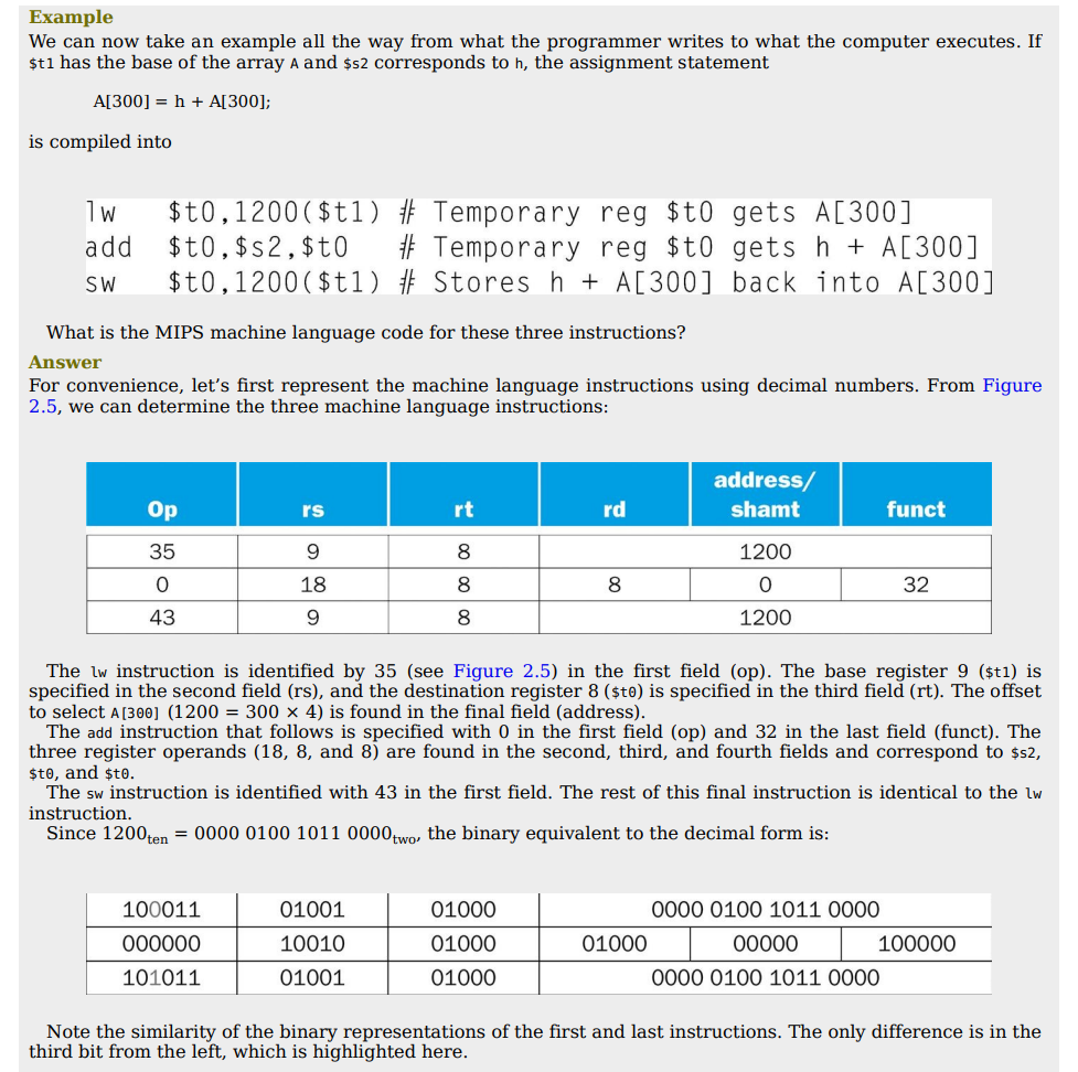
$s0-$s7map to registers16-23;$t0-$t7map to registers8-15. - Hexadecimal conversion is utilized for easier representation and understanding of binary instructions. (4 bits, 0-F) (base 16)
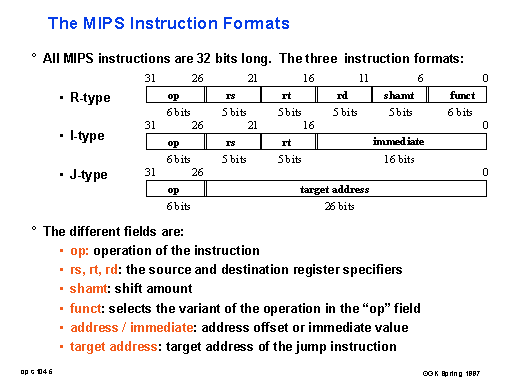
rs: First register source operand.rt: Second register source operand or destination register in I-type instructions.rd: Register destination operand (R-type only).- I-Immediate (addi,lw,sw) (Data transfer format, immediate), R-Register(add,sub) (arithmetic instruction format), J-Jump
Logical Operations
- Logical operations in MIPS:
AND,OR,NOR, shifts (sll,srl). sll(shift left logical) andsrl(shift right logical) move bits left/right, filling with 0s.ANDI(AND immediate) andORI(OR immediate) for operations with constants.- Shifting left by
ibits is equivalent to multiplying by. (dividing for srl) - Operations that can isolate a field in a word:
AND, and a combination of shifts (sllfollowed bysrl).
Instructions for Making Decisions
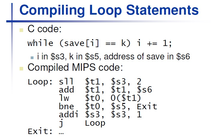
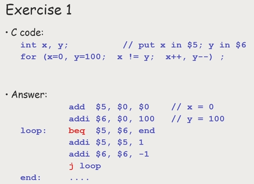
- Conditional Branching (also used for loops):
beq: Branch if equal.bne: Branch if not equal.
- Unconditional Branching:
j: Unconditional jump to label/address.
- Comparisons:
slt: Set on less than (signed comparison).sltu: Set on less than unsigned (for unsigned comparison).
- Immediate Comparisons:
slti: Set on less than immediate (signed).sltiu: Set on less than immediate unsigned.
Supporting Procedures in Computer Hardware
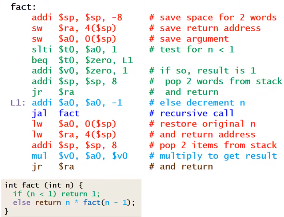
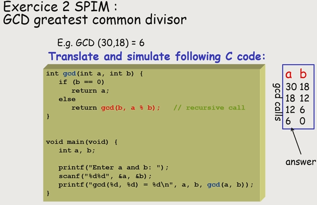
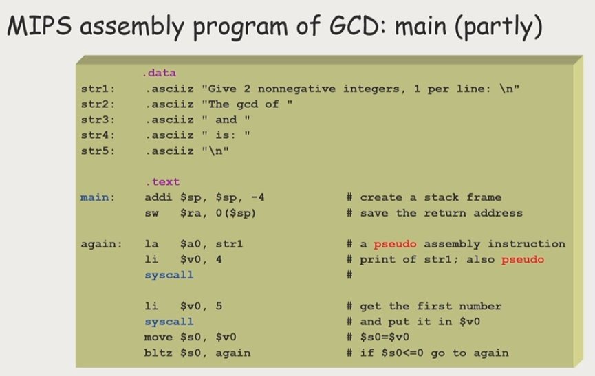
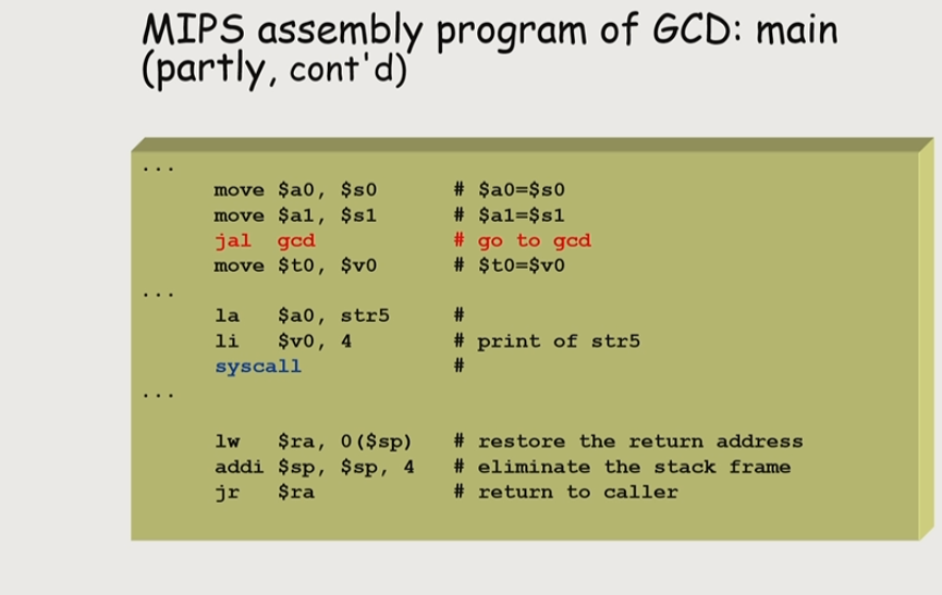
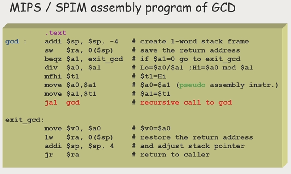
C to MIPS Procedures and the Stack
- Procedure Call Steps:
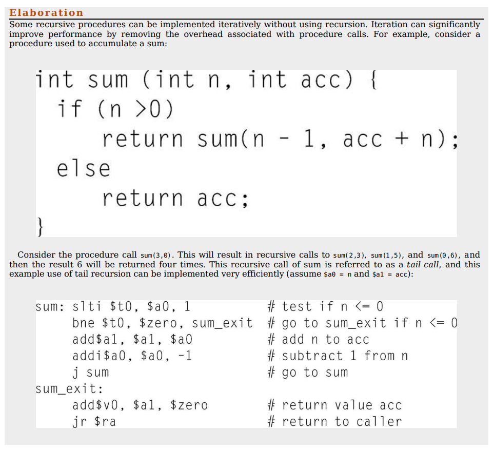
- Put parameters in accessible registers (
$a0-$a3). - Use
jal ProcedureAddressto jump and link to the procedure (savesPC+4). - Perform the task and place the result in return value registers (
$v0-$v1). - Return to the calling program using
jr $ra. $gbglobal pointer to static data
- Put parameters in accessible registers (
- Stack Management:
$sp: Stack pointer register.- Use stack for saving registers before calling procedures.
push: Add elements to the stack.pop: Remove elements from the stack.- LIFO queue
- Use stack to save
$raand arguments for recursive calls (non-leaf procedure).
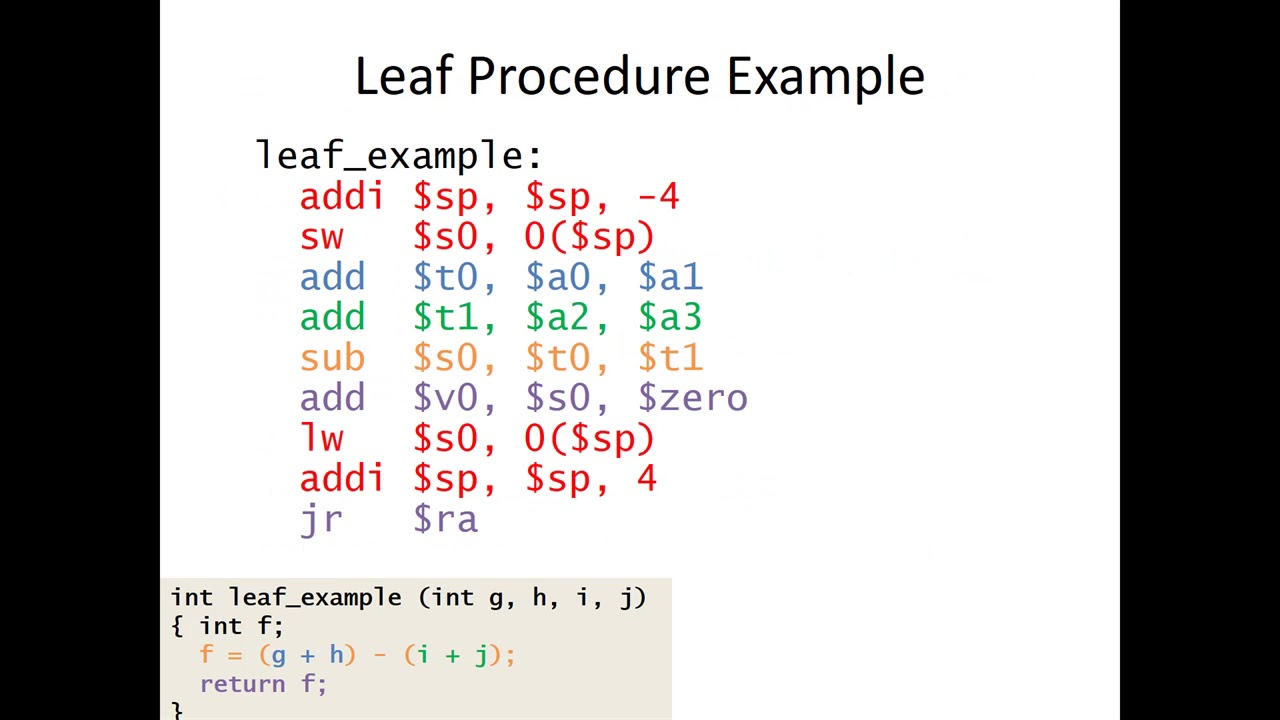
- adjust stack to have room for 1 item
addi - you could also have pushed space for
t0, t1and then popped
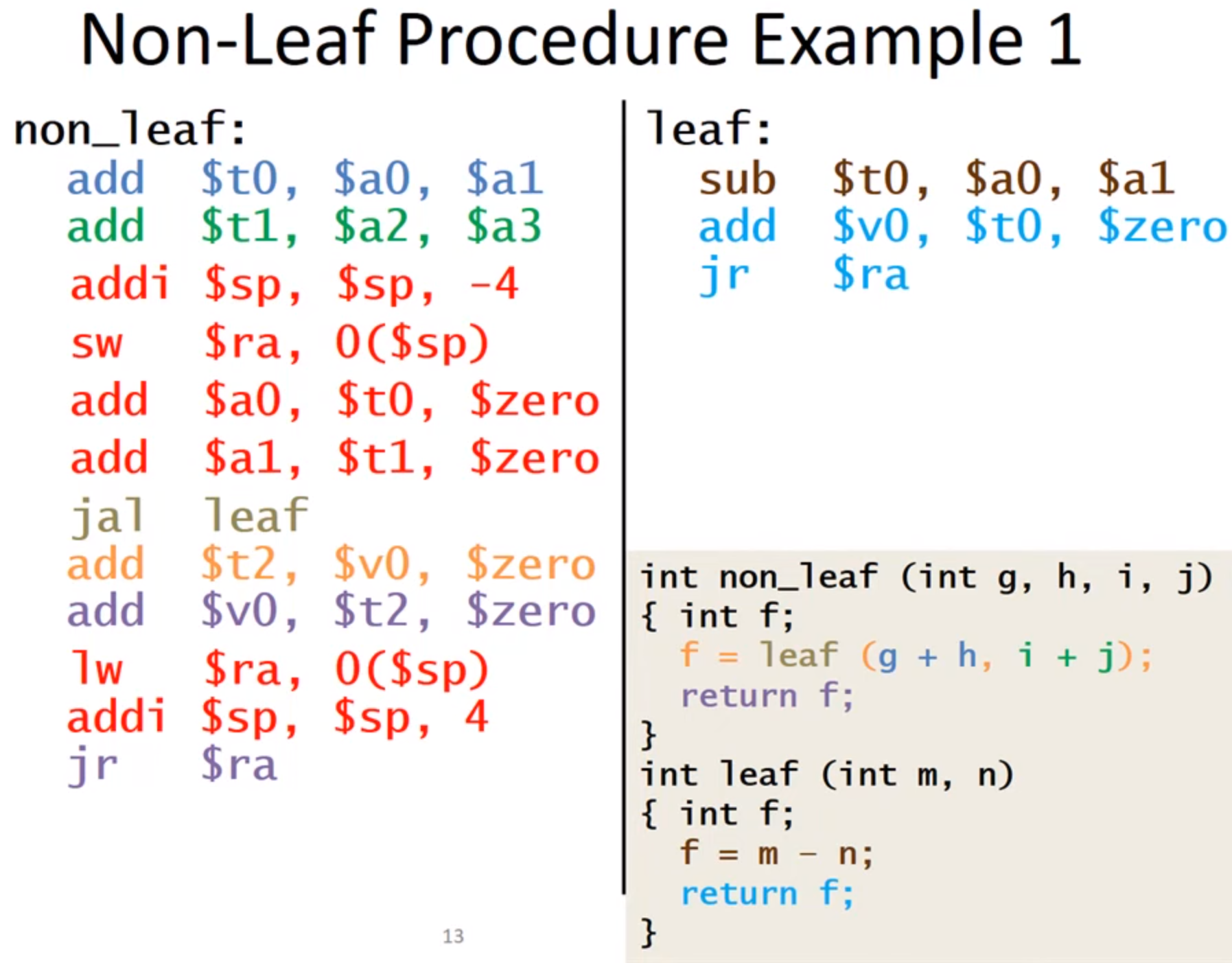
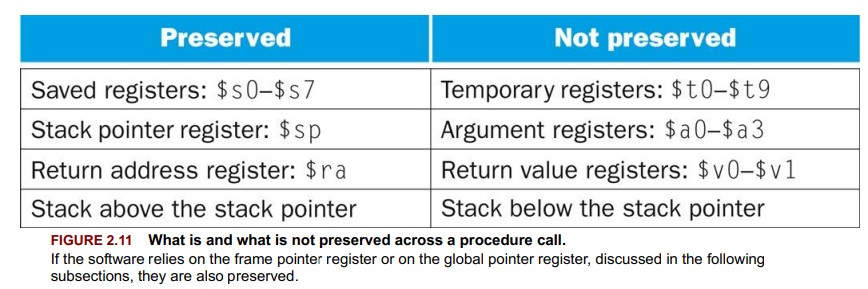
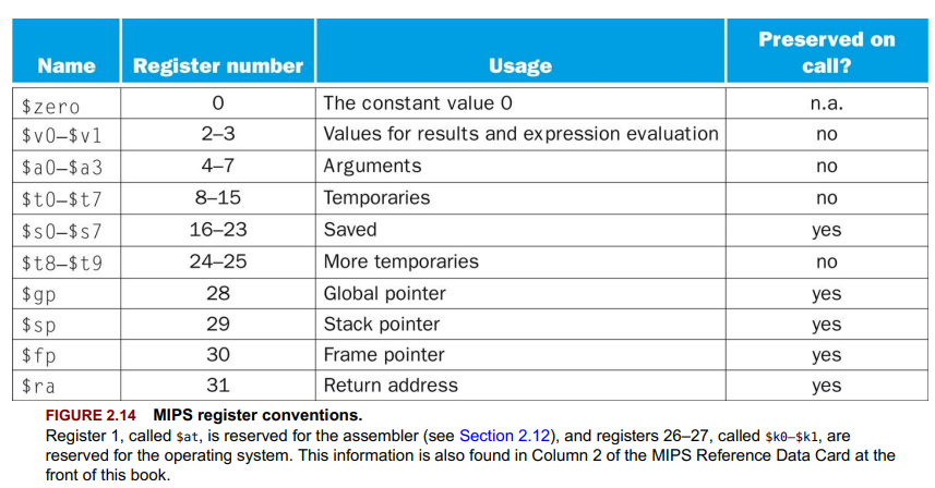
Difference between preserved and non preserved
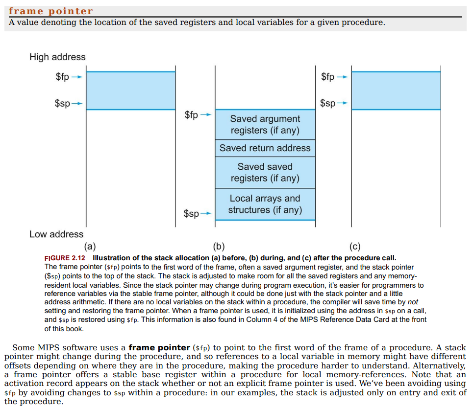
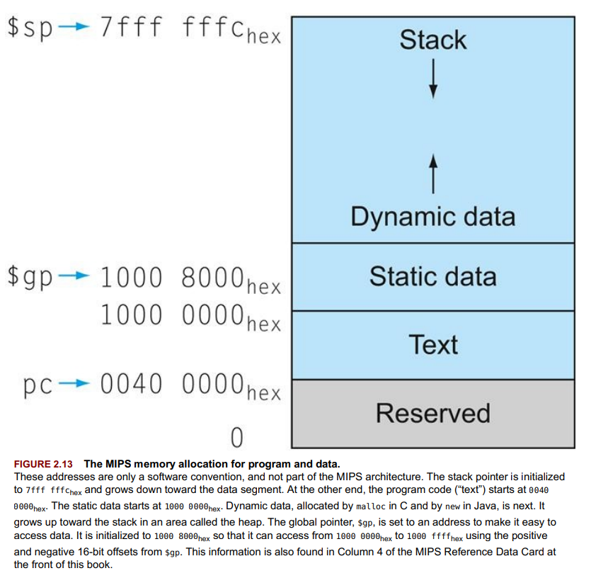
- Memory Segments for Programs:
- Text Segment: Contains machine code.
- Static Data Segment: For constants and static variables.
- Heap: For dynamically allocated data.
- Stack: For automatic variables and call stack.
Communicating with People
- ASCII uses 8-bit bytes for character representation, allowing for 256 unique symbols, Unicode 16-bit bytes(150,000 characters).
- Load byte (
lb, lbu) loads a byte from memory, placing it in the rightmost 8 bits of a register. Store byte (sb) takes a byte from the rightmost 8 bits of a register and writes it to memory. - MIPS instructions for 16-bit(
halfwords 2 bytes) quantities (lh,lhu,sh) facilitate operations with Unicode. (load half - lh)
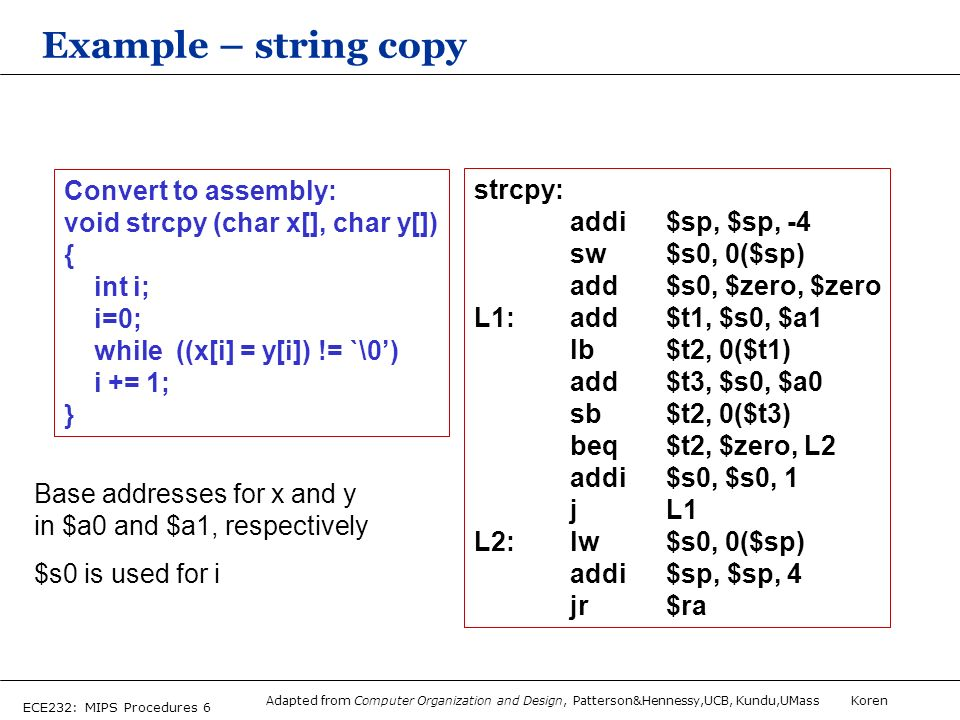
Exit loop if the character 0. Exit if last character of string.
MIPS Addressing for 32-bit Immediates and Addresses
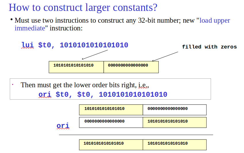
- 32-Bit Immediate Operands: Use
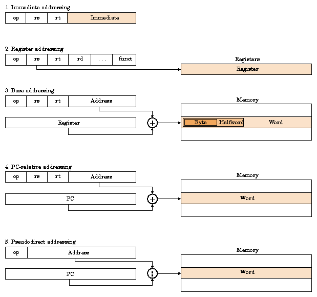
luito set upper 16 bits, thenori(or similar) for lower 16 bits. E.g.,lui $s0, 61thenori $s0, $s0, 2304.$attemp register to decode 32 bit constants. - Pseudodirect addressing → concatenated 26 bits of
$jwith upper PC bits
- Branching Far with MIPS: Use
bneandjto handle distant branches beyond 16-bit limit. E.g.,bne $s0, $s1, L2thenj L1. - Decoding MIPS Machine Code: Identify operation from op field, then use instruction formats and encoding tables to translate to assembly. E.g., 00af8020hex →
add $s0,$a1,$t7.
Parallelism and Instructions: Synchronization
- Data Race: Occurs with two memory accesses from different threads to the same location, at least one write, without synchronization.
- Atomic Operations for Synchronization: Essential for implementing locks and synchronization primitives to prevent data races.
- Atomic Exchange (Swap): Interchanges a register value with a memory value atomically; used to implement basic locks. E.g., 0 indicates lock is free, 1 indicates lock is taken.
- MIPS Synchronization: Utilizes
load linked (ll)andstore conditional (sc)instructions for atomic operations.llloads a value from memory;scattempts to store a value back, failing if the location was modified in-between.
- Usage of
llandsc:- For synchronizing threads in parallel programs to ensure correct reading/writing of shared data.
- In uniprocessor systems, for process synchronization with shared data.
Translating and Starting a Program
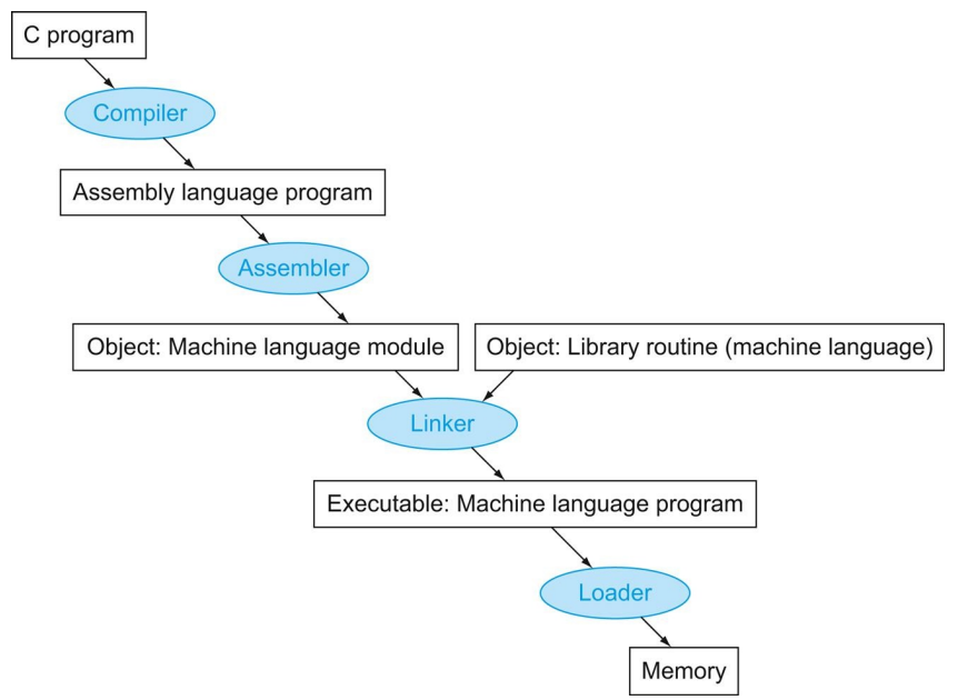
Compiling, assembling, and linking
- Compilation Process: Transforms C program to assembly, then to machine code.
- Linking: Combines multiple object modules and libraries, resolves references. (so we can compile each object file seperaly dont have to compile whole thing)
- Loading: Places executable into memory for execution.
- DLLs (Dynamically Linked Libraries): Libraries linked at runtime, not compile time, saving space and allowing updates.
- Key Concepts:
- Assembly language includes pseudoinstructions for easier programming.
- MIPS uses
ll(load linked) andsc(store conditional) for synchronization.
A C Sort Example to Put It All Together
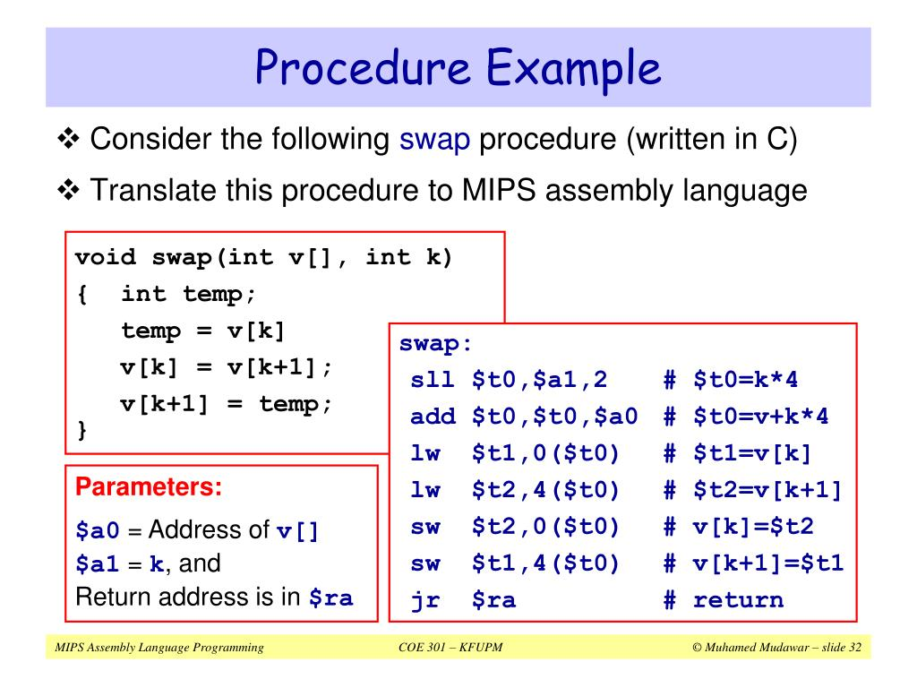
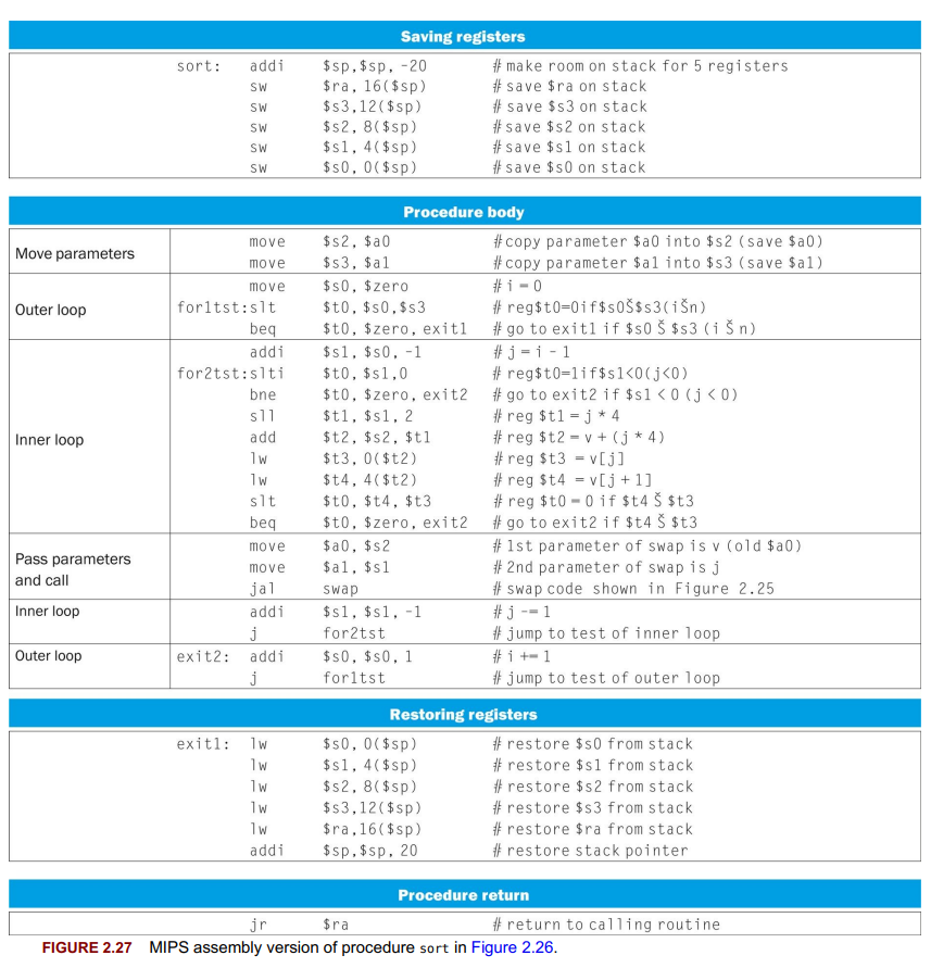
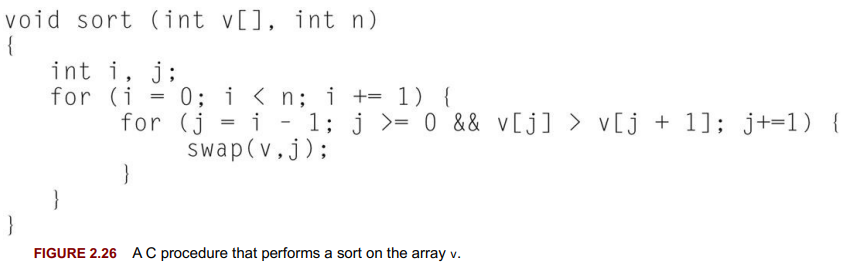
- Optimization: Compiler optimizations impact speed; procedure inlining reduces call overhead.
Arrays versus Pointers
- Array vs. Pointer in C to Clear Memory:
- Array (
clear1): Uses array indices. Loops increment index and calculate address each iteration. - Pointer (
clear2): Directly manipulates memory address. More efficient as it eliminates index-to-address calculation within loop.
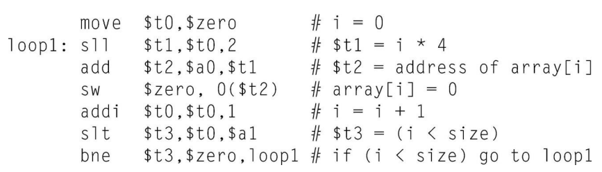
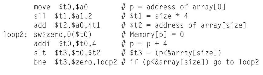
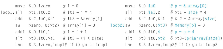
- Array (
- Optimization Insight:
- Pointer version is more efficient, moving constant calculations outside of loop, reducing instructions per iteration from 6 to 4.
- Compiler Role:
- Modern compilers can optimize array code to match pointer efficiency, negating the traditional performance rationale for using pointers.
MIPS Hazards, Branch Predictions
Topic: Processor Datapath and Pipelining
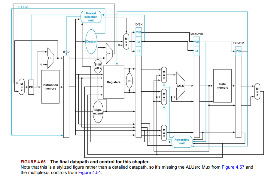
forwarding conditions exam questions
L8 4 forwarding - YouTube
you can bypass but at least one bubble is needed in between
- On the MIPS architecture, jump and branch instructions have a “delay slot”. This means that the instruction after the jump or branch instruction is executed before the jump or branch is executed.
Introduction
- Performance Factors: Instruction count, clock cycle time, CPI(cycles per instruction).
- MIPS Focus: Datapath & control for instruction execution.
Core Steps for Instruction Execution:
- Fetch instruction using PC (Program Counter).
- Read register(s) as instructed.
- Execute operation (ALU for arithmetic/logic, memory access for load/store, compare for branches).
- Write back results to register or update PC for branches.
- Components: ALU, registers, memory.
- Control: Multiplexors for source selection, control unit guides operations.
Logic Design Conventions
-
Logic Elements:
- Combinational: Output depends only on current inputs (e.g., ALU).
- State Elements: Contain internal storage, characterize computer state (e.g., registers, memory).
-
Clocking Methodology:
- Edge-Triggered: Updates occur at clock edge transition, ensuring predictable hardware operation. Sequential elements update on rising edge.
-
Control Signals: Direct operations; asserted (logically high) or deasserted (logically low). (used in multiplexor selection) (control unit sets them)
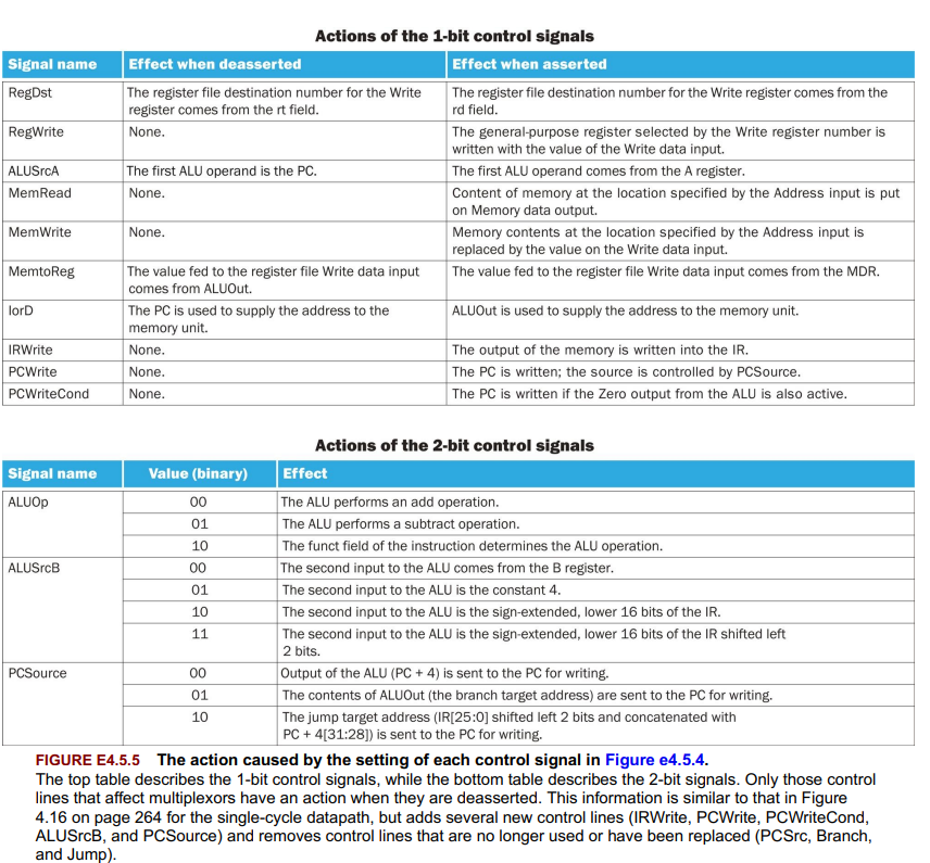
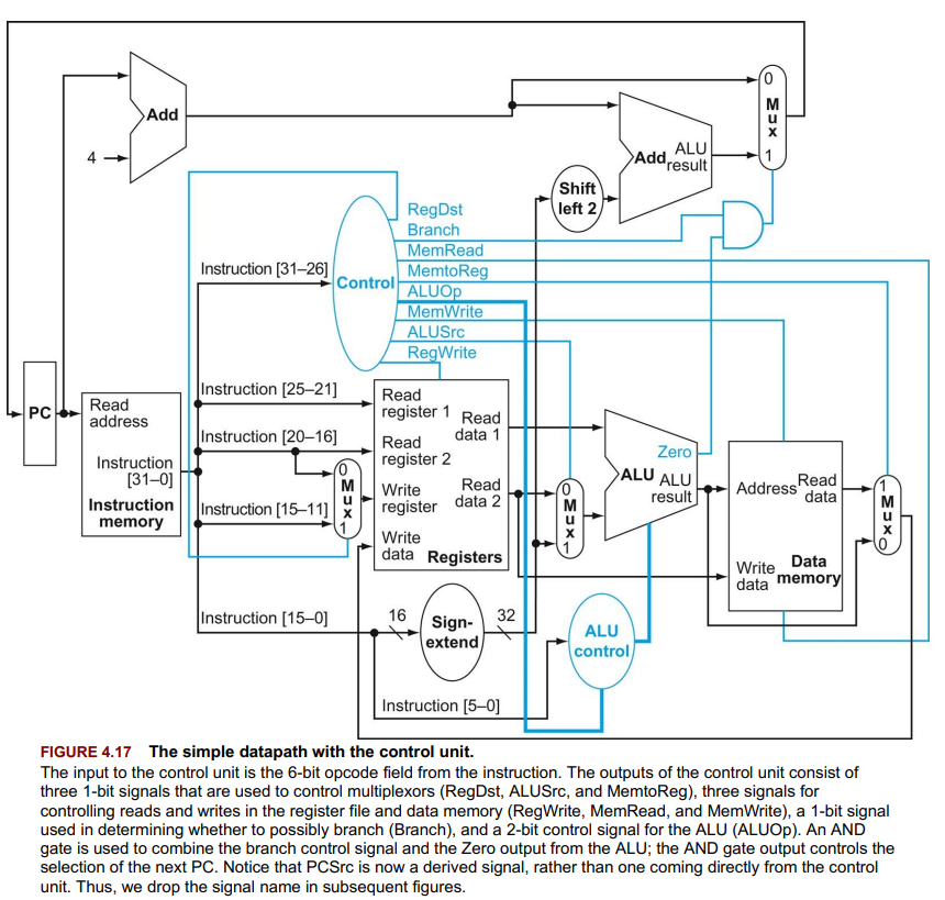
-
Design Implications:
- Edge-triggered allows reading and writing a register in the same cycle without indeterminacy.
- MIPS architecture primarily uses 32-bit wide paths for data handling.
-
Key Concept: Edge-triggered clocking prevents feedback within a single cycle, crucial for correct sequential logic operation.
-
False Statement: Multiple register files are not required for edge-triggered writes in MIPS datapath.
Building a Datapath
Topic: Processor Datapath and Pipelining
-
Components: Instruction memory, PC (Program Counter), adder (increments PC), register file, ALU, data memory, sign extension unit.
-
R-type Instructions:
- Operations: Read two registers, perform ALU operation, write result to register.
- Datapath Elements: Register file (reads/writes registers), ALU (executes arithmetic/logic).
-
Load/Store Instructions:
- Operations: Calculate memory address, load from or store to memory.
- Additional Elements: Sign extension unit (extends immediate values + 16 bits), data memory (reads/writes data).
-
Branch Instructions:
- Operations: Compare two registers, branch if equal.
- Additional Elements: ALU (compares registers), adder (calculates branch target address).
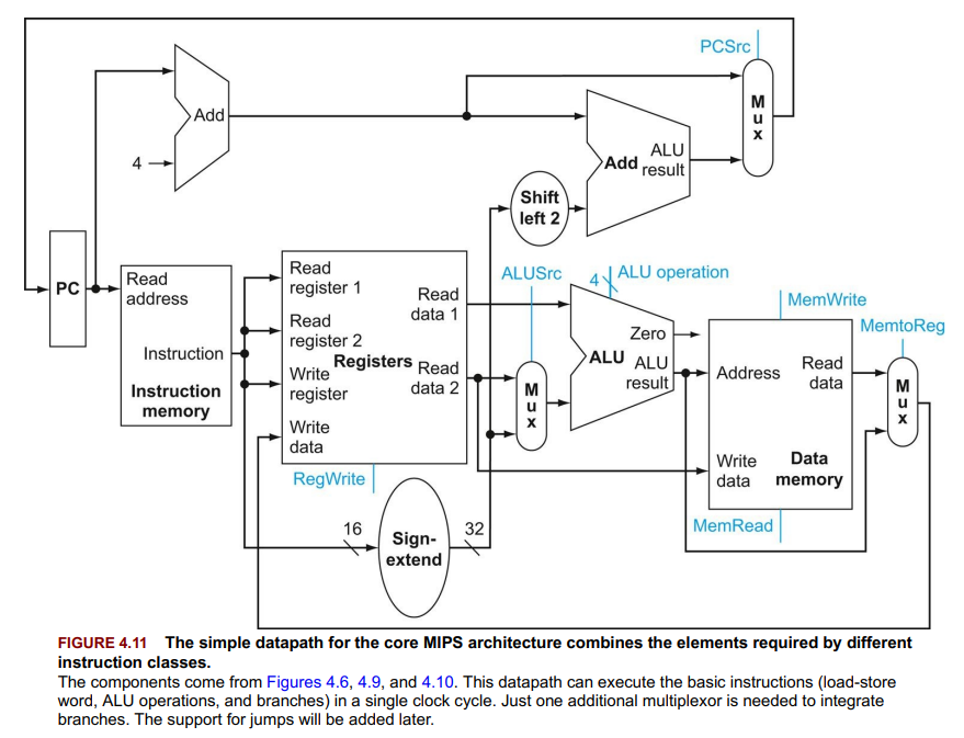
-
Single Datapath Design:
- Challenge: Accommodate all instruction types with minimal duplication.
- Solution: Use multiplexors to select between different sources/targets for ALU inputs and register writes.
A Simple Implementation Scheme
MIPS Single-Cycle Implementation
- Components: PC, ALU, register file, instruction/data memory.
- Operations: Instruction fetch, decode, ALU operation, memory access, write back.
- Control Logic: Decides ALU operation, memory read/write, and register write based on instruction type.
- Instruction Types: R-type, load/store, branch, jump.
- Limitation: Slow due to longest instruction path dictating clock cycle.
- Efficiency: Improved by pipelining, allowing simultaneous instruction execution.
- dont care term: element of a logical function in which the output does not depend on the values of all the inputs.
A Multicycle Implementation
1 4 1 Multicycle Operations - YouTube
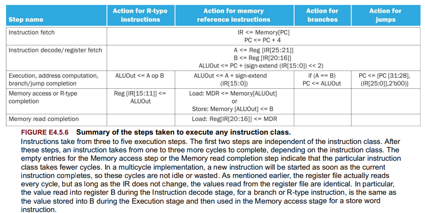
- Multicycle Implementation: Executes instructions over multiple cycles, sharing functional units. (each step in the execution will take 1 clock cycle).
- Components: Single memory for code/data, one ALU, additional registers (IR, MDR, A, B, ALUOut) for data holding.
- Execution Steps: Fetch, decode, execute, memory access/write-back, with steps varying by instruction type.
- Control: Managed by a finite-state machine, varying control signals per cycle.
- Instruction Cycles:
- Loads: 5 cycles
- Stores: 4 cycles
- R-type: 4 cycles
- Branches: 3 cycles
- Jumps: Direct PC update.
- CPI: Varies by instruction mix; more efficient than single-cycle due to hardware reuse, less efficient than pipelining.
An Overview of Pipelining
Topic: Processor Datapath and Pipelining
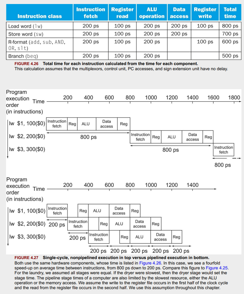
- Pipelining: Technique to overlap instruction execution, improving throughput without affecting latency per instruction.
- MIPS Pipeline Stages: 5 - Fetch, Decode, Execute, Memory Access, Write Back.
- Hazards:
- Structural: Hardware cannot support all instruction combinations simultaneously.
- Data: Instruction waits for previous instruction’s result.
- Control: Branches and instructions altering program flow introduce decision delays.
- Solutions:
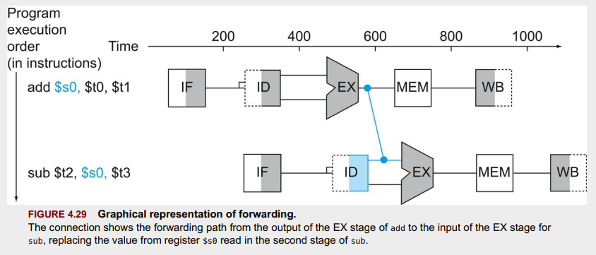
- Forwarding: Direct data transfer between stages to resolve data hazards.
- Stalling: Introduces delays (“bubbles”) for hazard resolution.
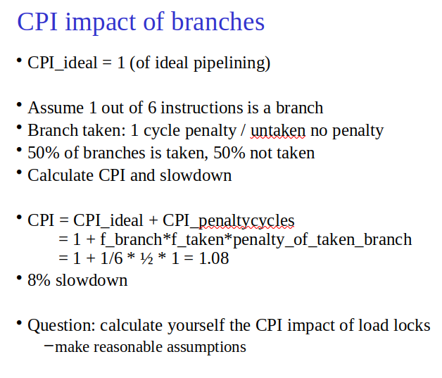
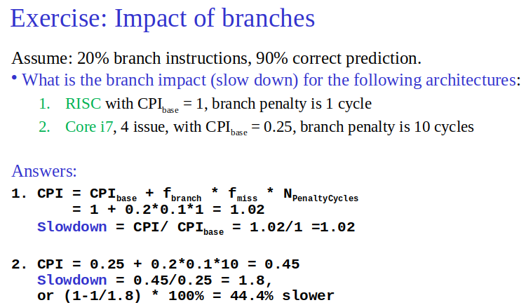
- Branch Prediction: Predicts branch decisions to maintain flow; incorrect predictions cause stalls.
- Impact: Pipelining improves instruction throughput, not the execution time of individual instructions. Designed for efficient pipelining with uniform instruction lengths and limited formats.
- 1 3 4 Structural Hazards&Data Hazards - YouTube
- L8 5 control hazards - YouTube
Pipelined Datapath and Control
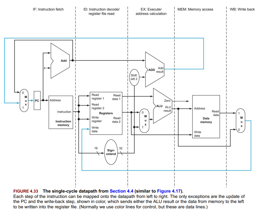
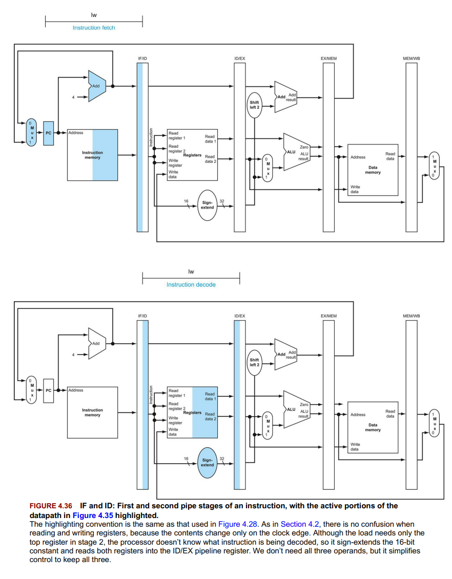
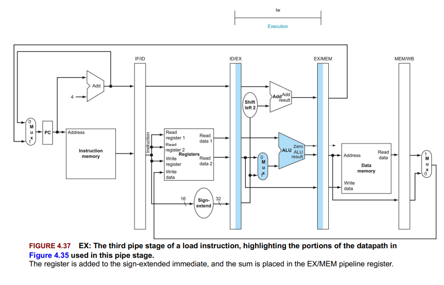
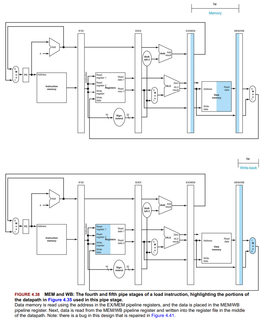
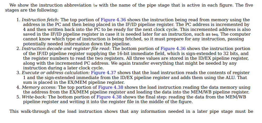
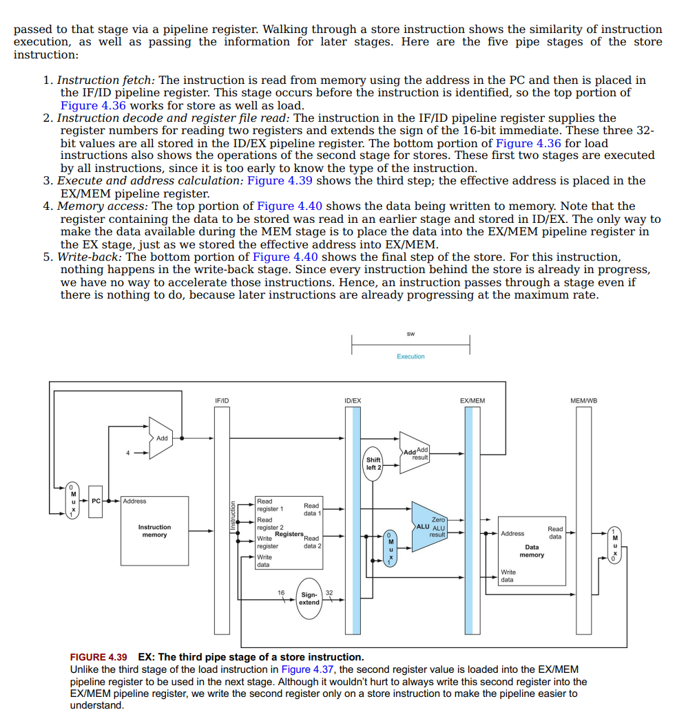
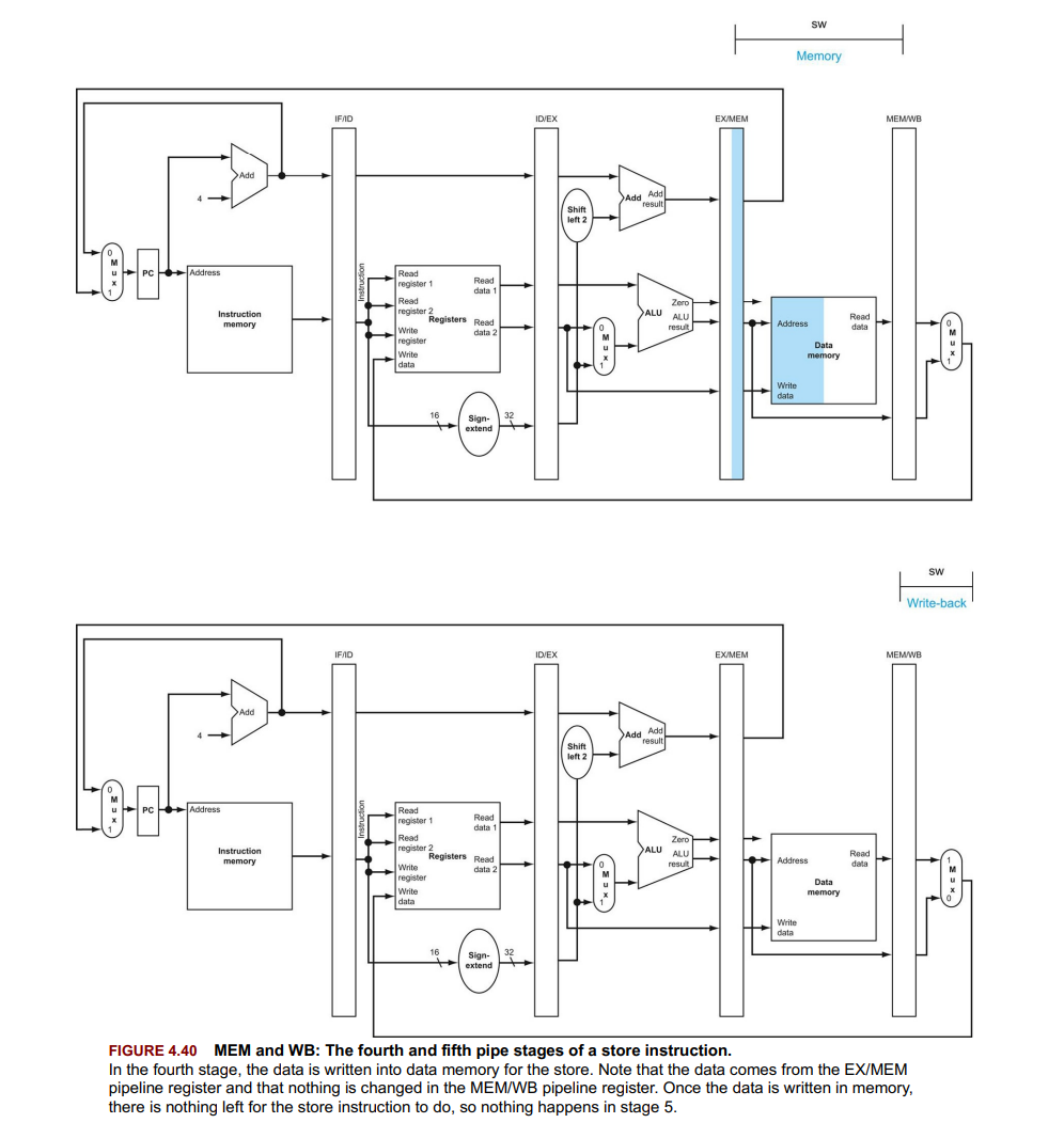
- Data Flow Exceptions: Write-back to register file and PC selection for branch instructions occur in reverse direction but don’t affect current instruction execution. First right-to-left flow of data can lead to data hazards and the second leads to control hazards.
- Pipeline Registers: Named after stages they separate (e.g., IF/ID).
- Control Lines Grouped: By stages. Key ones are
RegDst,ALUOp,ALUSrcfor EX;Branch,MemRead,MemWritefor MEM;MemtoReg,RegWritefor WB. - Control Implementation: Set during ID, passed down with extended pipeline registers.
Data Hazards: Forwarding versus Stalling
Topic: Processor Datapath and Pipelining
- Data Hazards: Instructions depend on the results of previous instructions.
- Forwarding: Directly passes results to dependent instructions, reducing wait times.
- Stalling: Inserts NOPs(no operation instructions) to wait for necessary data, used when forwarding is not feasible.
- Hazard Detection: Identifies need for forwarding or stalling.
- Added multiplexors select between normal data flow and forwarded data.
- Control logic determines when and where to forward data or insert stalls.
- Load-Use Hazard: Requires stalling due to immediate data dependency on load instruction.
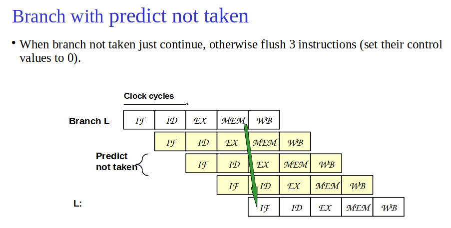
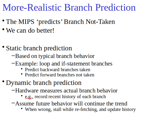
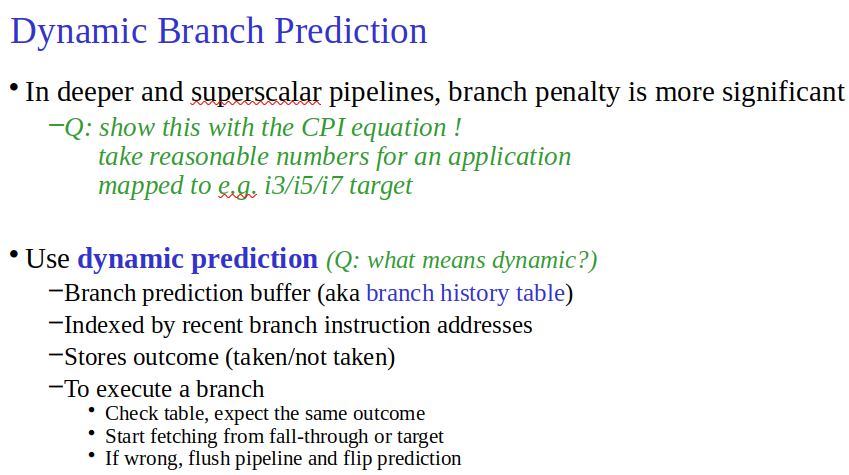
- Branch Prediction: Dynamically guesses the outcome of branches to maintain pipeline flow, significantly reducing stalls caused by control hazards.
Exceptions
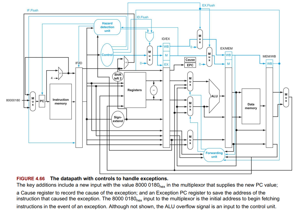
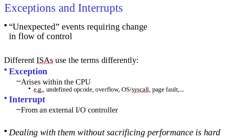
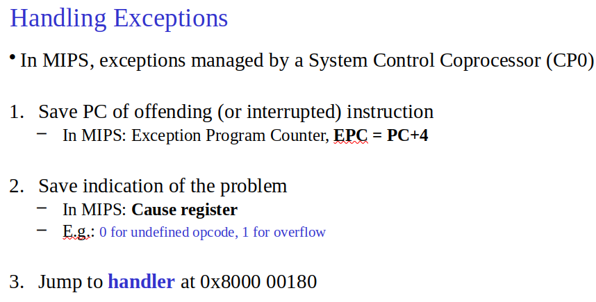
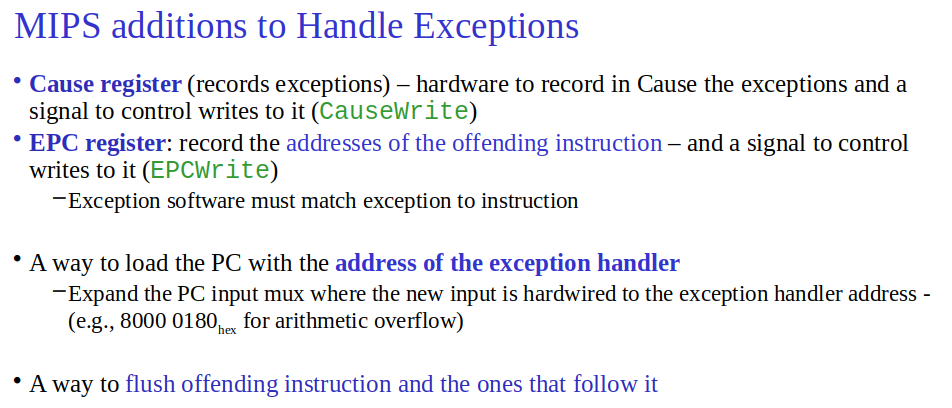
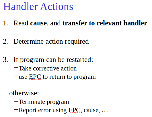
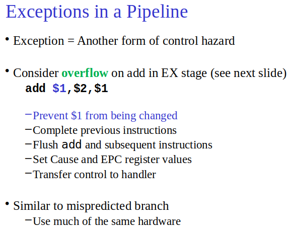
- Exceptions in Pipelining: Use EPC(Exception Program Counter) to save the offending instruction’s address; transfer control to OS. Interrupt the flow.
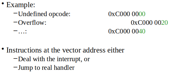
- MIPS Handling: Single entry point for exceptions at
8000 0180hex. EPC and Cause register are key. - Pipelined Handling: Flush following instructions, treat them as nops, ensure correct flow with EPC and Cause register.
- Types: Include arithmetic overflow, undefined instructions (internal), and I/O requests (external).
- Vectored Interrupts: Handler address determined by the cause (instead of a fixed address for every exception)
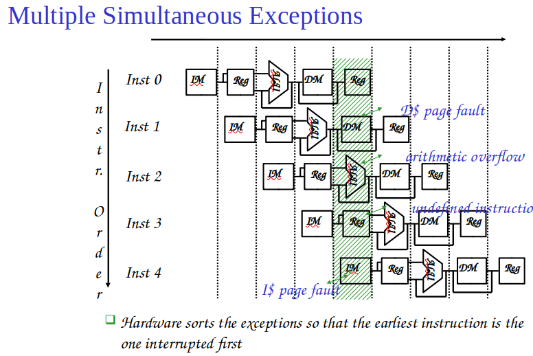
- Implementation: Flush pipeline on exceptions, save instruction address in EPC, record cause, OS takes action.
- Precise vs. Imprecise Interrupts(Just stop pipeline and save state, handler workout): MIPS supports precise, associating each interrupt with its instruction.
- Exceptions: internal in processor, Interrupt: External
Parallelism via Instructions
What Is Instruction Level Parallelism (ILP)? - YouTube
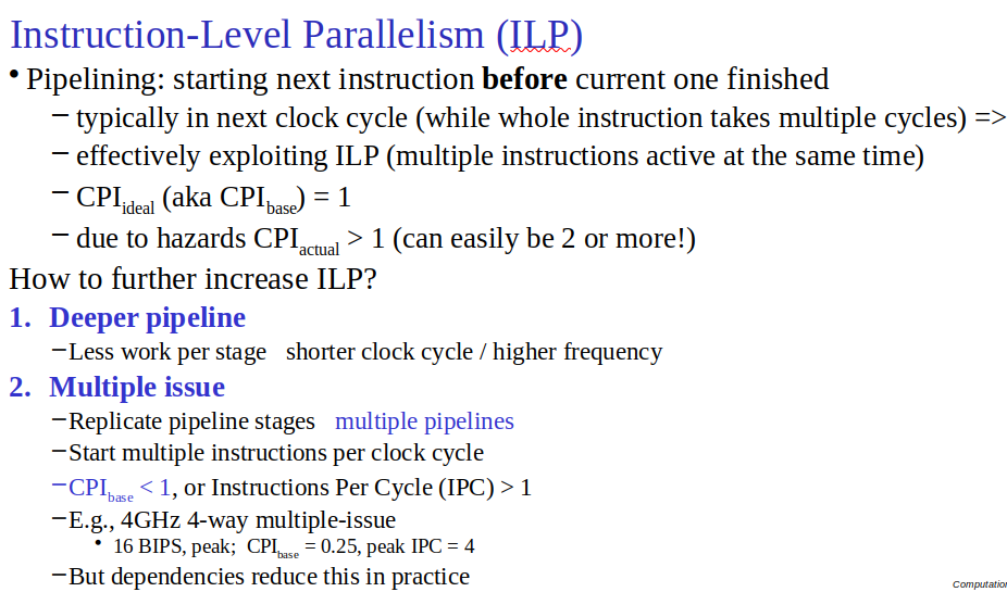
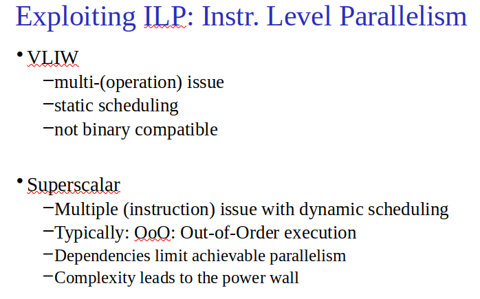
- ILP (Instruction-Level Parallelism)
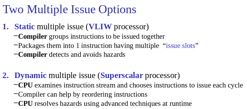
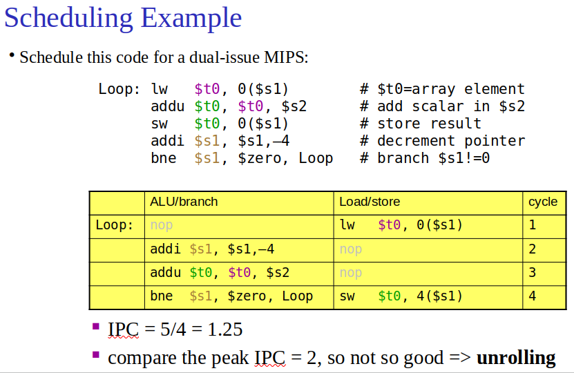
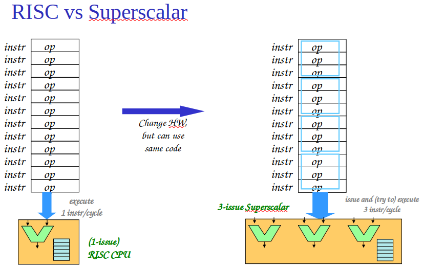
- Multiple Issue: Execute multiple instructions per clock cycle; requires duplicating internal components.
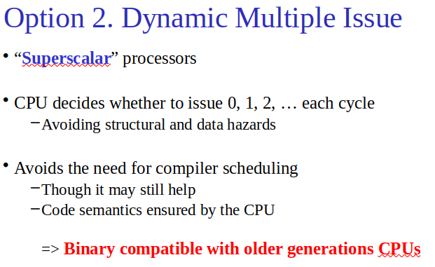
- Static vs. Dynamic Issue: Static (compiler decides which instructions issue together), dynamic (processor decides during execution).
- Speculation: Guess the outcome of instructions to execute others that depend on them. Must handle wrong guesses.
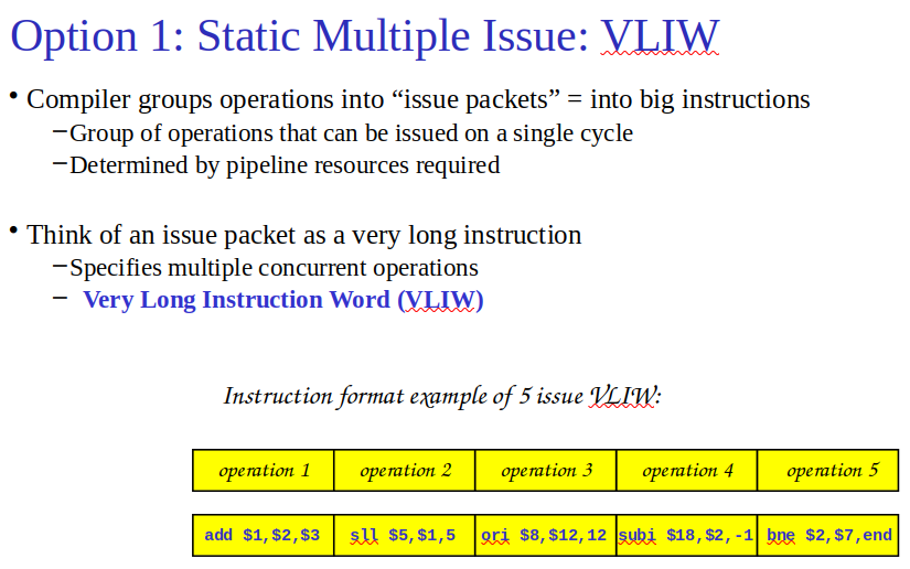
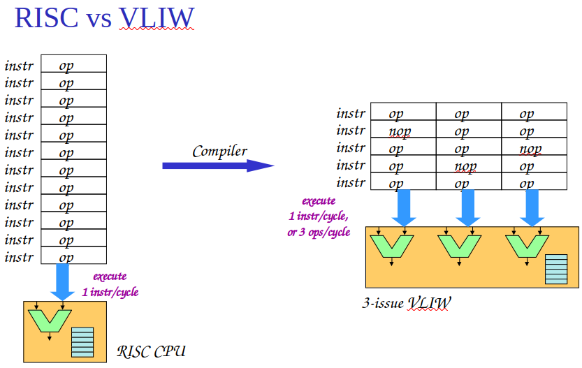
- VLIW (Very Long Instruction Word): Compiler groups instructions into large “issue packets” for execution. (Fill instruction issue slots with NOPs if necessary)
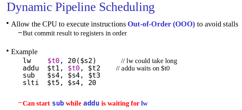
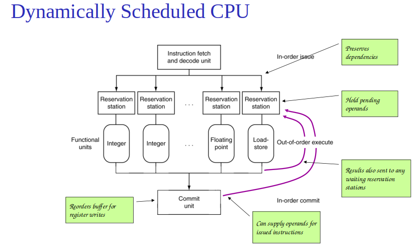
- Dynamic Scheduling: Processor reorders instruction execution to avoid stalls, using buffers like reservation stations and reorder buffers.
- In a statically scheduled processor instructions start execution in program order while in a dynamically scheduled processor instructions can start execution out of order.
- Superscalar Processors: Issue multiple instructions per cycle dynamically; manage hazards and instruction flow in hardware.
Putting It All Together: The Intel Core i7 6700 and ARM Cortex-A53
- ARM Cortex-A53: Dual-issue, 8-stage pipeline, uses branch prediction, ideal CPI of 0.5, stalls from hazards and cache misses.
- Intel Core i7 6700: 14-stage pipeline, translates x86 to micro-ops, register renaming, aggressive branch prediction, six execution units, average CPI of 0.71, performance affected by branch mispredicts and cache misses.
- arm v7 addressing modes checkout.
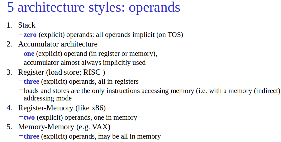
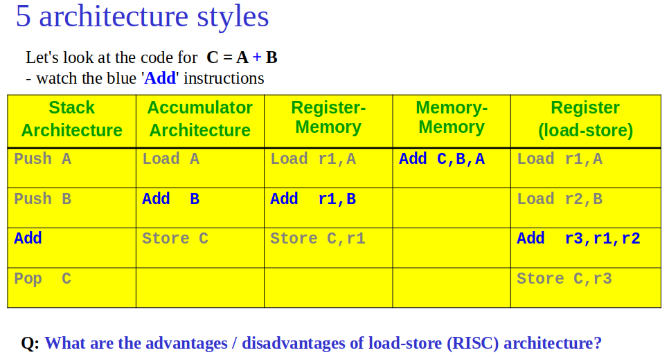
- RISC is a load store architecture.
Going Faster: Instruction-Level Parallelism and Matrix Multiply
- DGEMM Optimization: Loop unrolling and C intrinsics significantly boost DGEMM performance, leveraging AVX instructions for enhanced parallelism.
- Unrolling Impact: Unrolling exposes more operations for parallel execution, nearly doubling DGEMM performance.
- Performance Gains: Optimizations yield a 4.4x speedup over basic DGEMM, 4600x faster than Python.
Operating Systems, Multi-Issue, Other Architectures
- instruction can consist of multiple operation for instance for VLIW, one operation can be 32 bits → an instruction has to be done fully.
- reduce frequency → operation takes longer → good for power → usually tend to increase. For energy doesn’t change unless voltage changes.
Parallelism and Computer Arithmetic: Subword Parallelism, Real Stuff: Streaming SIMD Extensions and Advanced Vector Extensions in x86, Going Faster: Subword Parallelism and Matrix Multiply
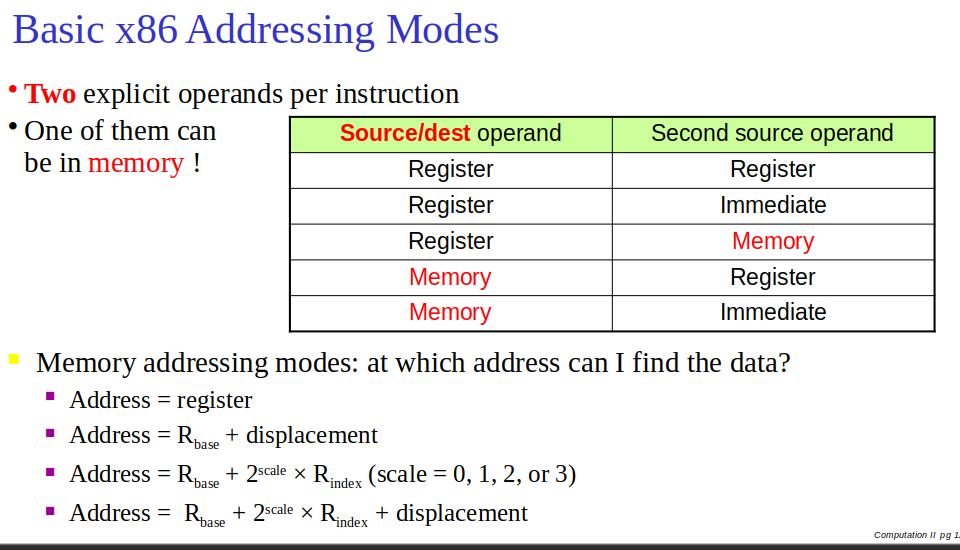
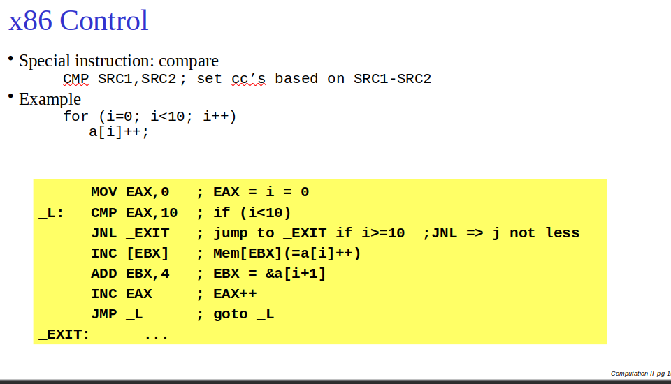
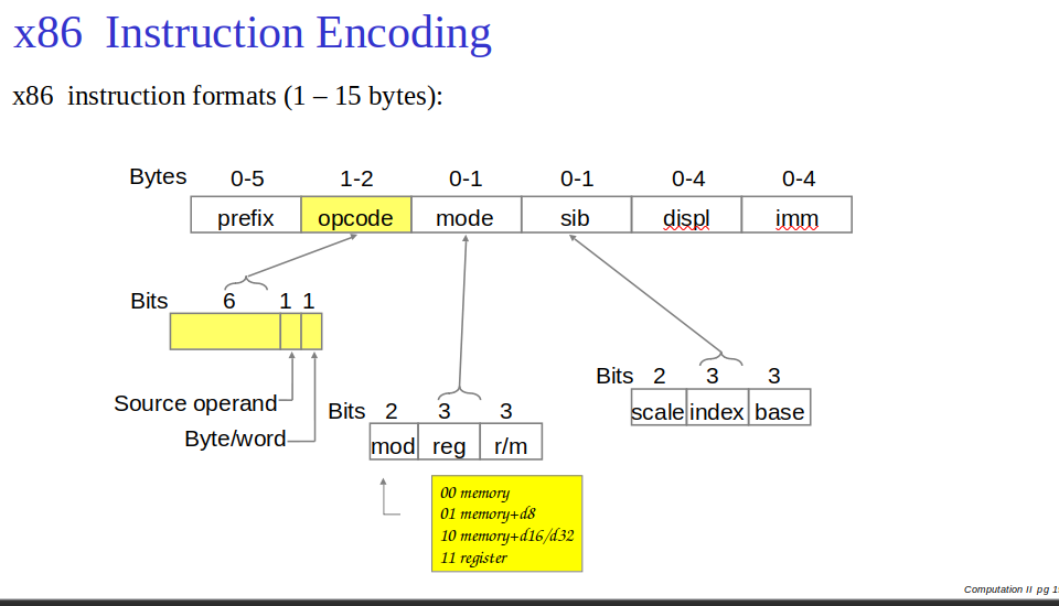
x86 controll can be improved with funny loop
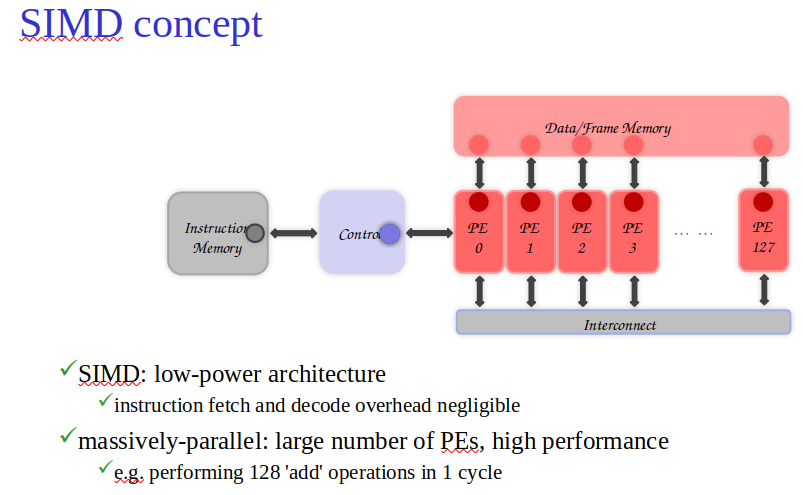
- Subword Parallelism: Enhances performance by operating on multiple data elements within a single instruction, leveraging SIMD (Single Instruction, Multiple Data) capabilities for multimedia applications.
- NEON in ARM: Offers over 100 instructions for subword parallelism, supporting various data sizes from 8-bit to 64-bit integers and 32-bit floating-point numbers, excluding 64-bit floating point.
- SSE/SSE2 in x86: Introduced to handle multimedia tasks with operations on 128-bit data, later expanded with AVX to 256-bit and AVX512 to 512-bit registers, increasing parallelism for floating-point operations.
- DGEMM Optimization with AVX512: Utilizes subword parallelism for significant speedup in matrix multiplication, showcasing the impact of SIMD extensions on computational efficiency.
- Performance Boost: AVX implementation of DGEMM achieves a 7.5x speedup, closely approaching the theoretical 8x improvement expected from using parallel operations.
Introduction to Operating Systems
Topic: Processes, Threads and Synchronization
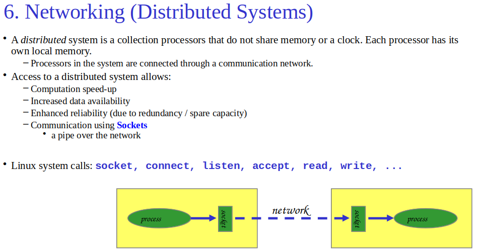
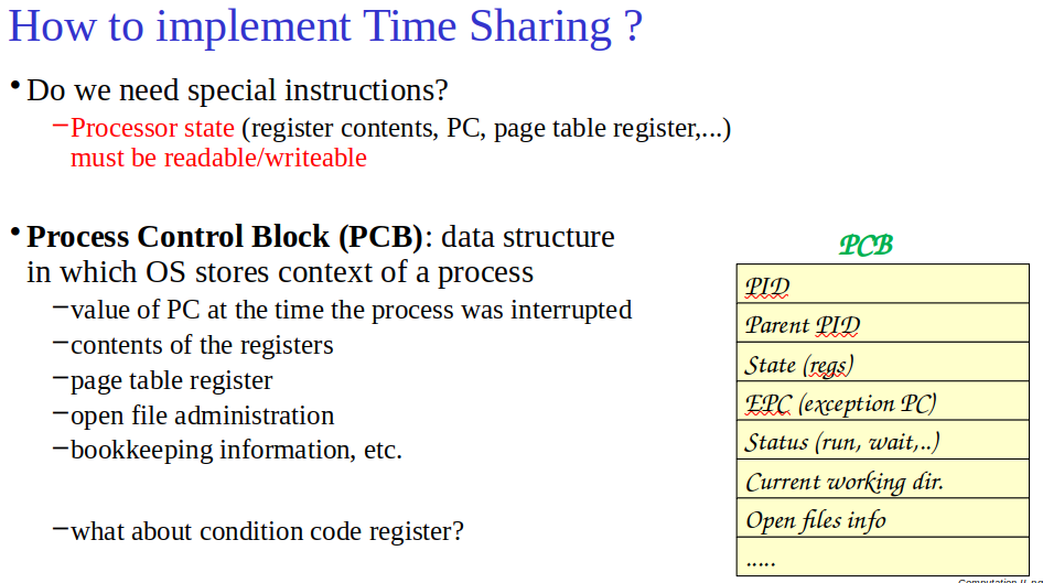
- Computer System Levels:
- Level 0: Digital Logic/Gate Level
- Level 1: Microarchitecture (registers, ALU, datapath, control)
- Level 2: Instruction Set Architecture (ISA) - Hardware/software interface
- Level 3: Operating System - Adds system calls for easier programming
- Level 4: Assembly Language - Can make system calls; questionably a separate level
- Level 5: Problem-Oriented Language - High-level languages for application programming
- Key Concepts:
- OS Level: Adds user-friendly system calls for tasks like file I/O.
- Virtual Memory: Extends with paging and segmentation.
- Concurrent Processing: Manages multiple processes simultaneously.
- Process Synchronization: Coordinates processes sharing data.
- Threads: Implements lightweight processes for efficient task management.
- File management
Virtual Memory
Difference Between Paging and Segmentation - GeeksforGeeks
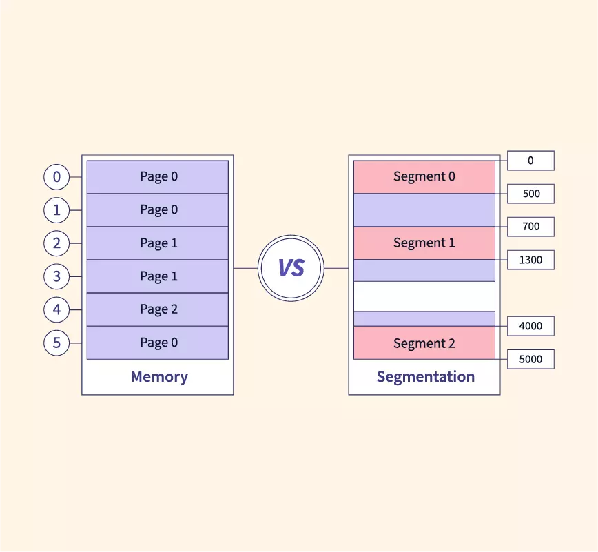
Virtual Memory
- Paging: Splits memory into fixed-size pages.
- Issue: Can’t easily handle growing/shrinking data.
Segmentation
- Allows dynamic growth/shrinkage of program parts.
- Segments: Independent address spaces prevent overlap.
- Addressing: Requires segment number + internal address.
- Benefits:
- Supports dynamic data structures.
- Enables detailed access protection.
- Reduces memory for shared programs.
Implementation
- 2 different ways to implement segmentation:
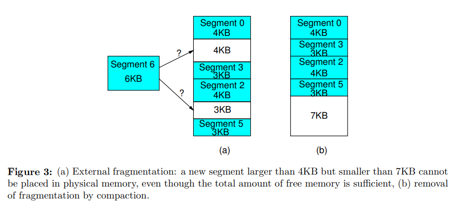
- Swapping: Entire segments stored contiguously in physical memory. Suffers from external fragmentation.
- Paged Segmentation: Divides segments into pages placed anywhere in memory. Combines paging benefits with segmentation flexibility.
- UNIX: Uses single page table, divides space into text, data, and stack segments.
Key Concepts
- Segmentation addresses paging limitations.
- UNIX uses a simplified segmentation model.
Formulas
- Virtual Address = Segment Number | Virtual Page Number | Page Offset
- Physical Address = Physical Page Number + Page Offset
Concurrent Processing
Key Points
- Concurrent Processing: Allows multiple programs to run simultaneously on a single-CPU system via time sharing.
- OS can temporarily suspend the current process and let another process run. In this way, a higher degree of CPU utilization can be achieved. Operating systems that support this are often called multiprogramming systems.
- Linux Processes:
- Created with
fork(). - New program execution via
execv(). - Communicate through pipes.
- Created with
Process Management
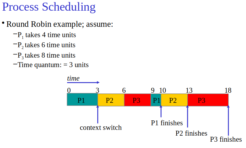
- First come first serve, shortest job first
- Scheduling: Round Robin method assigns time quantum, cycles through processes. Preemptive
- States: Processes are in Running, Ready, or Waiting states.
Protection
- Mode Bit: Separates user mode from system mode, controlling access to privileged instructions.
- Memory Protection: Uses paging, restricting process access to own memory space.
Concepts
- Context Switch: Saving and restoring process state for CPU handoff.
- Process Scheduler: Algorithm that selects the next process for execution.
Process Synchronization
Topic: Processes, Threads and Synchronization
Concepts
- Critical Section: Code accessing shared resources, requiring mutual exclusion.
- Race Conditions: Unpredictable outcomes from concurrent access.
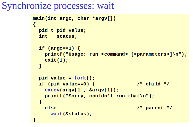
waitfor child to terminate
Solutions
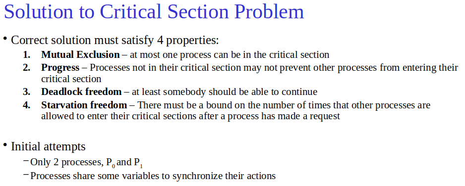
- Disabling Interrupts: Simple, not suitable for multi-CPU.
- Software Approaches:
- Strict Alternation: Uses
turnvariable, causing unnecessary waiting. - Warning Flags: Attempts to signal intent to enter critical section; can deadlock.
- Peterson’s Algorithm: Combines alternation and flags; guarantees mutual exclusion, progress, and fairness.
- Strict Alternation: Uses
- Hardware Approaches:
- TSL (Test-And-Set Lock): Hardware solution for atomic access.
Semaphores
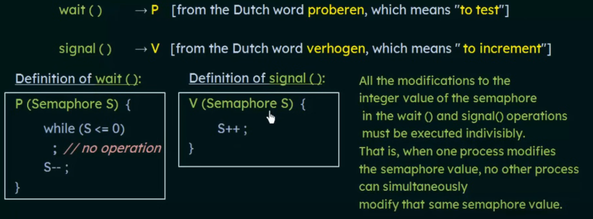
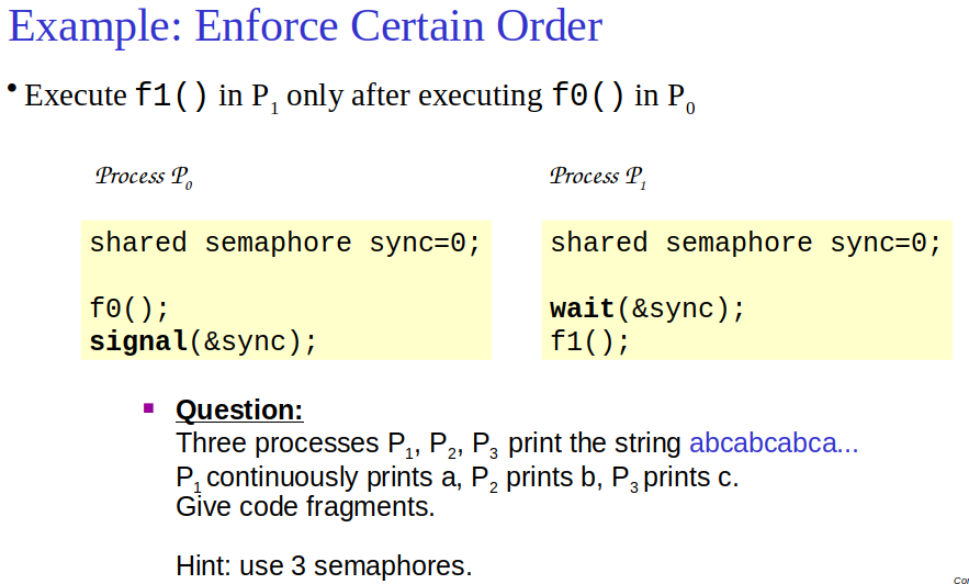
- Integer variable accessible only through atomic
waitandsignaloperations. - Usage: Control access and order of process execution.
- Advantages: Suitable for any number of processes, avoids busy waiting via process sleeping.
- mutex a binary semaphore → used in threads
Classical Problems
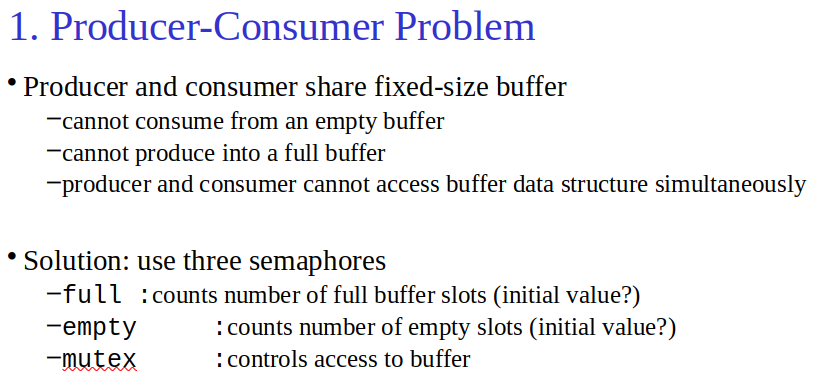
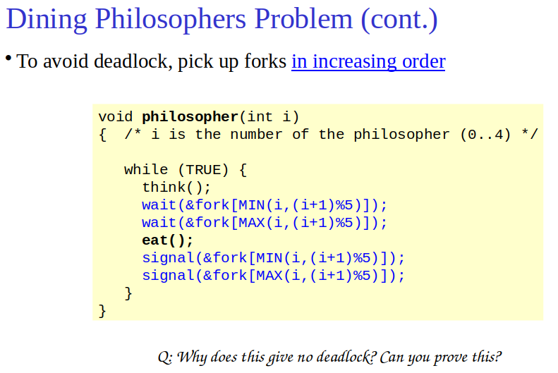
- Producer-Consumer: Managed with semaphores for safe buffer access.
- Dining Philosophers: Illustrates deadlock risk and strategies to avoid it. Avoid by picking up the fork in increasing order
Key Points
- Atomicity: Essential for operations on shared resources.
- Semaphores: Key tool for managing concurrent process interactions.
Threads
Topic: Processes, Threads and Synchronization
Difference between Process and Thread - GeeksforGeeks
Concepts
-
Threads: Execute concurrently in the same address space, enabling efficient communication and context switching.
-
switching from one thread to another can be much cheaper than switching between processes, because they do not need to be protected against each other.
-
Lightweight processes sharing the same address space.
-
Efficient context switching and inter-thread communication.
-
process vs thread: different processes cannot share the same memory space (code, variables, etc) whereas different threads in the same process share the same memory space. Threads are lightweight whereas Processes are heavyweight.
Key Functions
- Creation, exit, synchronization (e.g.,
pthread_create,pthread_exit,pthread_join).
Features
- Share data via global variables.
- Use mutexes for mutual exclusion.
Implementation Highlights
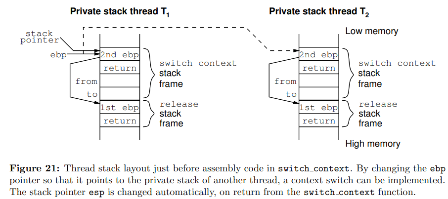
- Context includes program counter, stack pointer, base pointer.
new_threadinitiates threads with specific function and stack size.- Context switching swaps stack pointers between threads.
- Communication through channels, enabling synchronized exchanges.
Example: Sieve of Eratosthenes
- Threads filter primes in a pipeline, dynamically creating new threads for new primes.
Efficiency
- Threads offer a model for concurrent execution with minimal overhead, ideal for tasks requiring frequent interaction or shared data access.
Memory/JVM, Cache, I/O, Virtual Memory and SIMD (Memory Hierarchy)
Topic: Caches and Memory Hierarchy
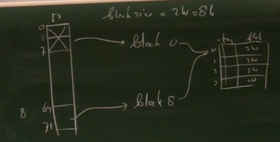
Introduction to Large and Fast: Exploiting Memory Hierarchy
Principles of Locality
- Temporal: Recently accessed data likely needed soon.
- Spatial: Data near recently accessed data likely needed soon.
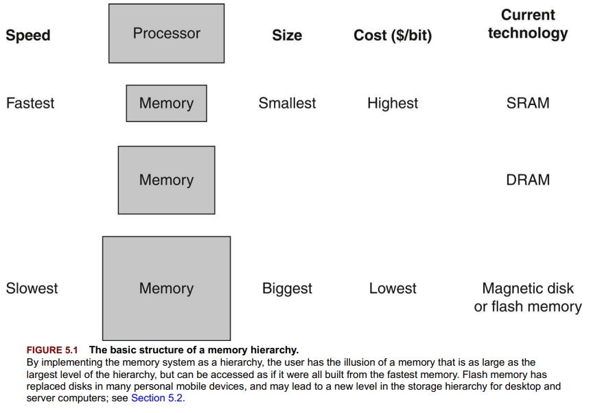
Memory Hierarchy Structure
- Layers of memory vary by speed, size, cost.
- Goal: Combine speed of fast memory with capacity and cost of slow memory.
Key Terms
- Block/Line: Smallest data unit managed in hierarchy.
- Hit: Data found in upper memory level.
- Miss: Data not found, requiring lower level access.
Performance Measures
- Hit Time: Time to access data in upper level.
- Miss Penalty: Time to retrieve and place data from lower to upper level.
Impact
- Memory hierarchies create the illusion of a large, fast memory system.
- Efficient hierarchy usage demands understanding data locality principles.
Memory Technologies
Technologies
- SRAM: Fast, expensive, used for caches. Access: 0.5-2.5 ns, Cost:
1000/GiB. - DRAM: Slower, cheaper, main memory. Access: 50-70 ns, Cost:
6/GiB. - Flash: Nonvolatile, secondary storage in devices. Access: 5-50 µs, Cost:
0.12/GiB. - Magnetic Disk: High capacity, slowest. Access: 5-20 ms, Cost:
0.02/GiB.
Key Points
- SRAM and DRAM differ in speed, cost, and density.
- Flash memory, nonvolatile with wear leveling, bridges gap between DRAM and disks.
- Magnetic disks offer highest capacity at lowest cost but slowest access.
Performance vs. Cost
- Faster memory = higher cost.
- Hierarchies balance access speed with storage cost.
The Basics of Caches
Topic: Caches and Memory Hierarchy
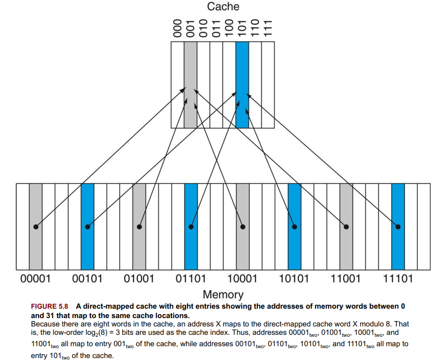
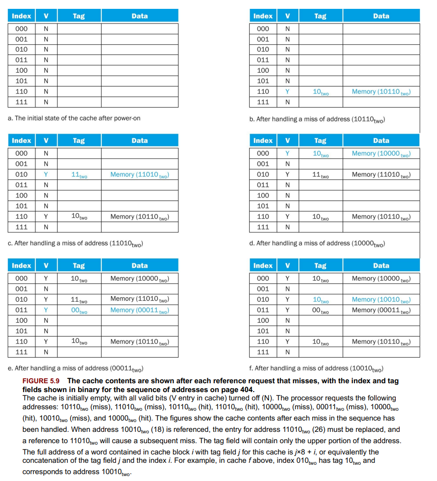
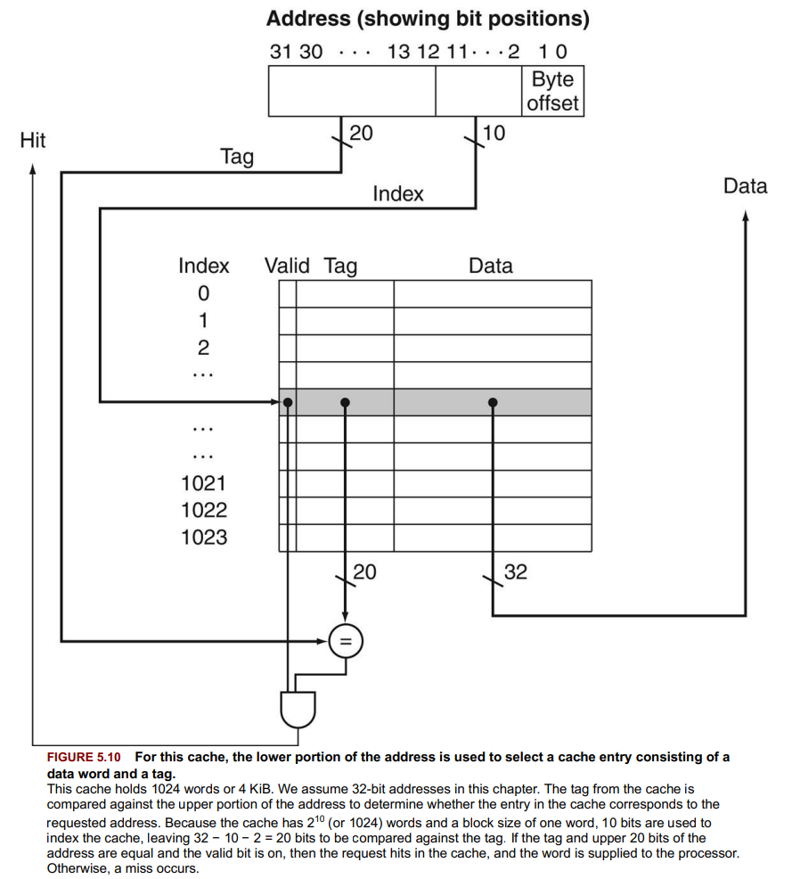
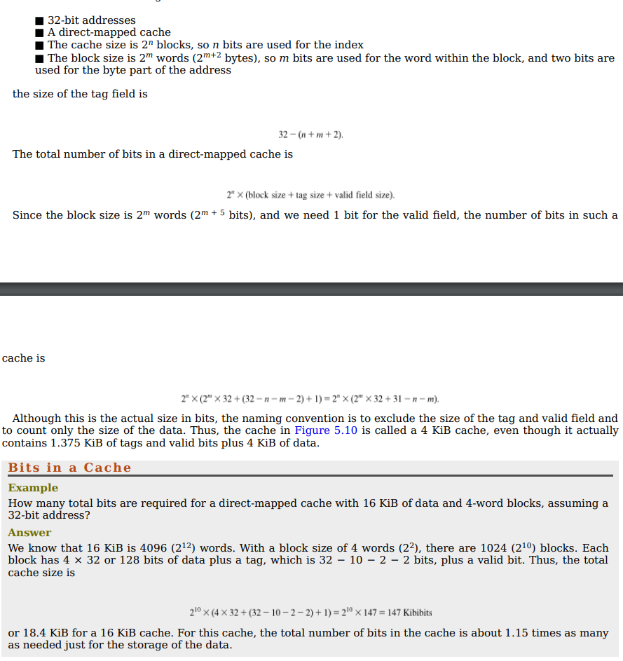
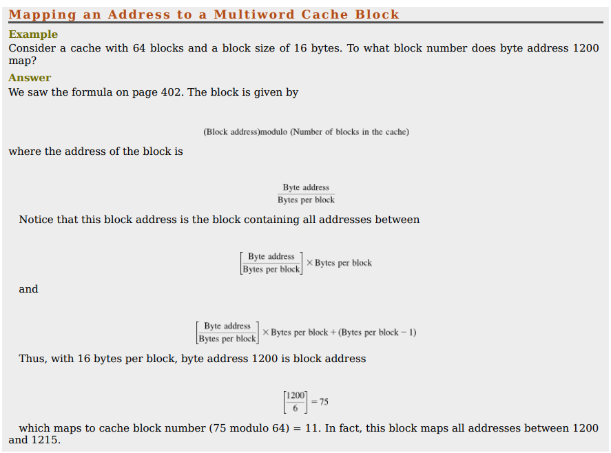
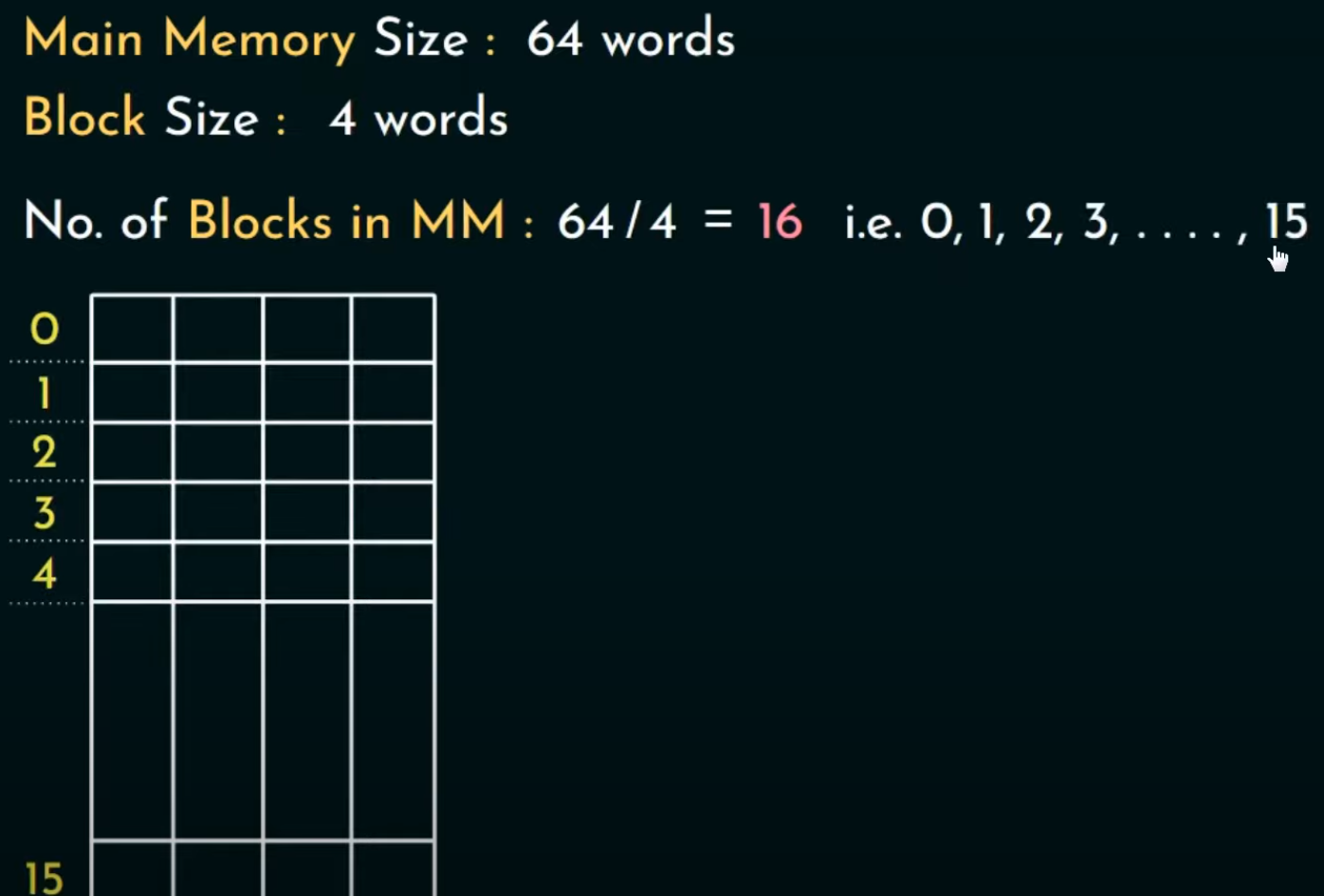
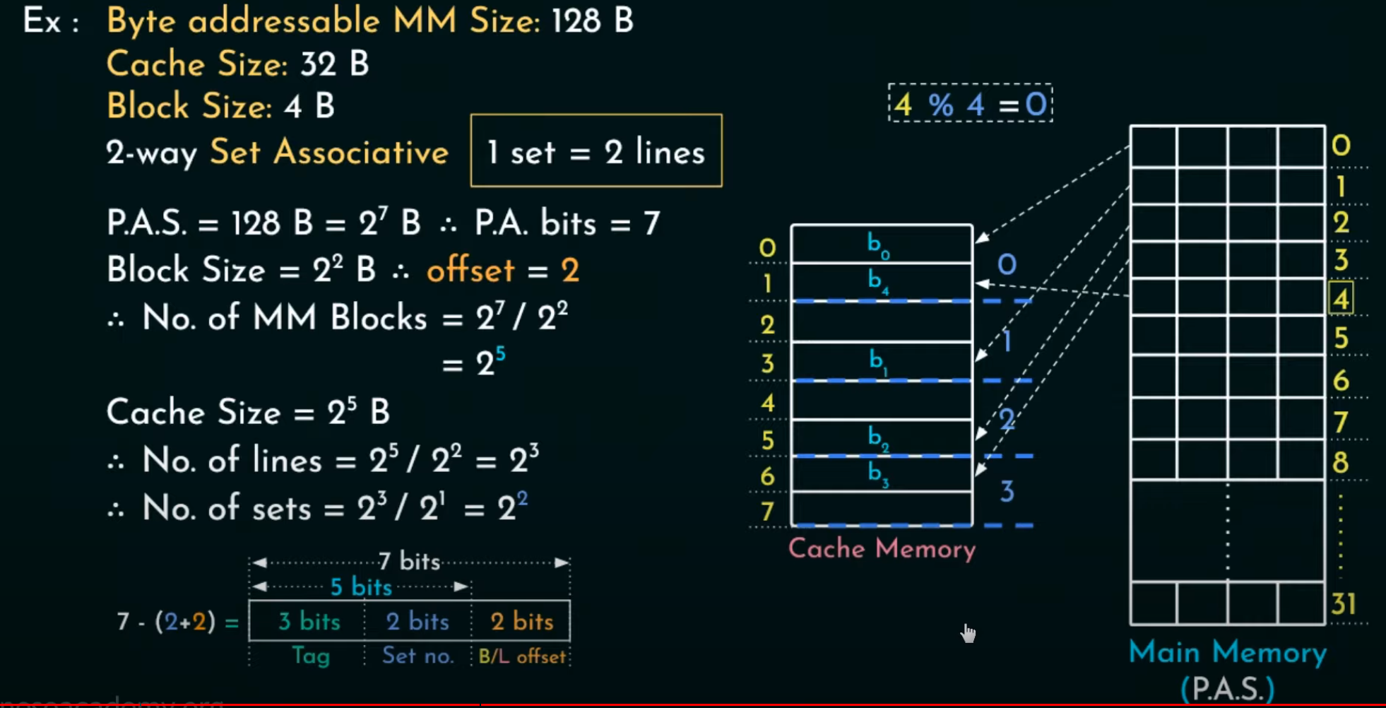
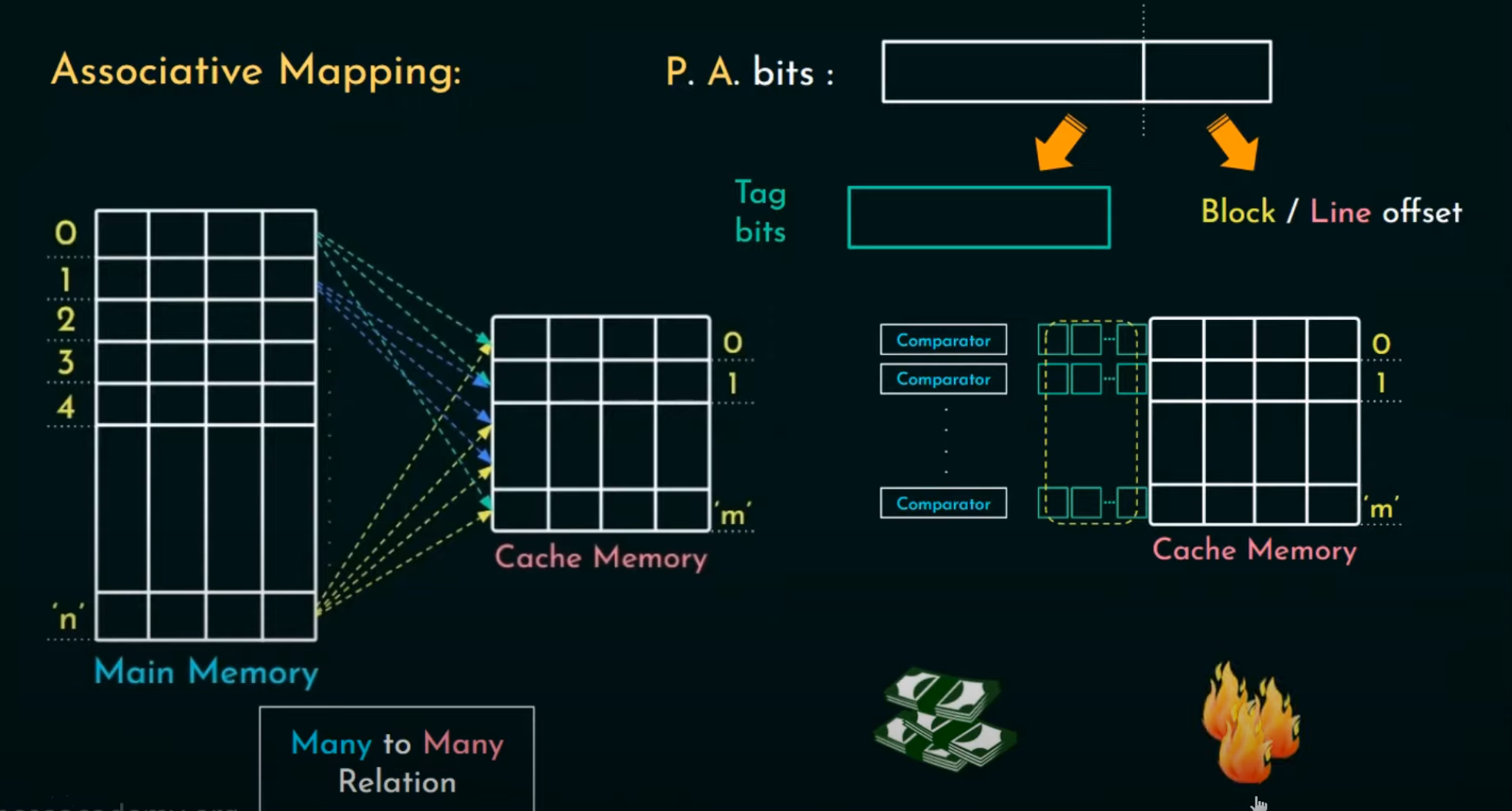
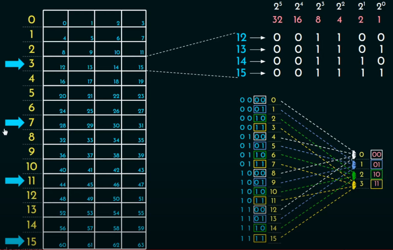
- Cache: Middleman between processor and main memory.
- Direct Mapped: One memory spot maps to one cache spot.
- Tags & Valid Bit: Identify if data in cache matches request.
- Write Strategies:
- Write-Through: Updates cache and memory simultaneously.
- Write-Back: Updates memory only when cache block replaced.
Access Steps
- Address to Cache: Checks if data is in cache.
- Hit or Miss: If miss, fetch from memory and refill cache.
Accessing a Cache
- Read Requests: Simple; involve checking tag and valid bit.
- Write Requests: More complex due to maintaining cache and memory consistency. Options include write-through and write-back strategies.
Intrinsity FastMATH Example
- 16 KiB Instruction and Data Caches: 16 words/block.
- Writes: Can choose between write-through and write-back.
- Miss Rates: Show how often data isn’t found in cache.
Key Points
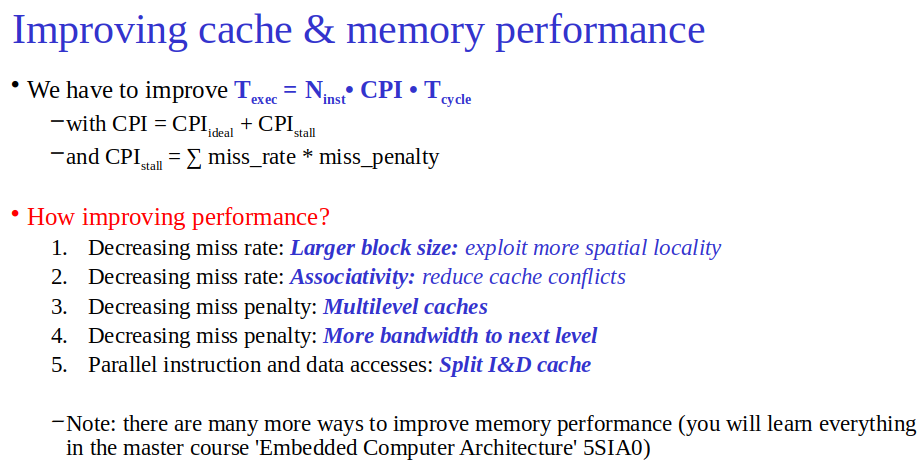
- Larger cache blocks exploit spatial locality but increase miss penalty.
- Cache Blocks: Larger blocks reduce miss rate but increase miss penalty.
- Memory Bandwidth: Crucial for transferring large blocks efficiently.
- Write Buffer: Mitigates stall times in write-through caches. (A queue that holds data while the data is waiting to be written to memory.)
Measuring and Improving Cache Performance
Topic: Caches and Memory Hierarchy
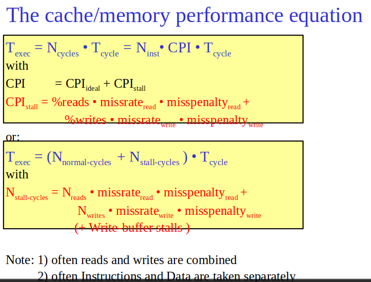
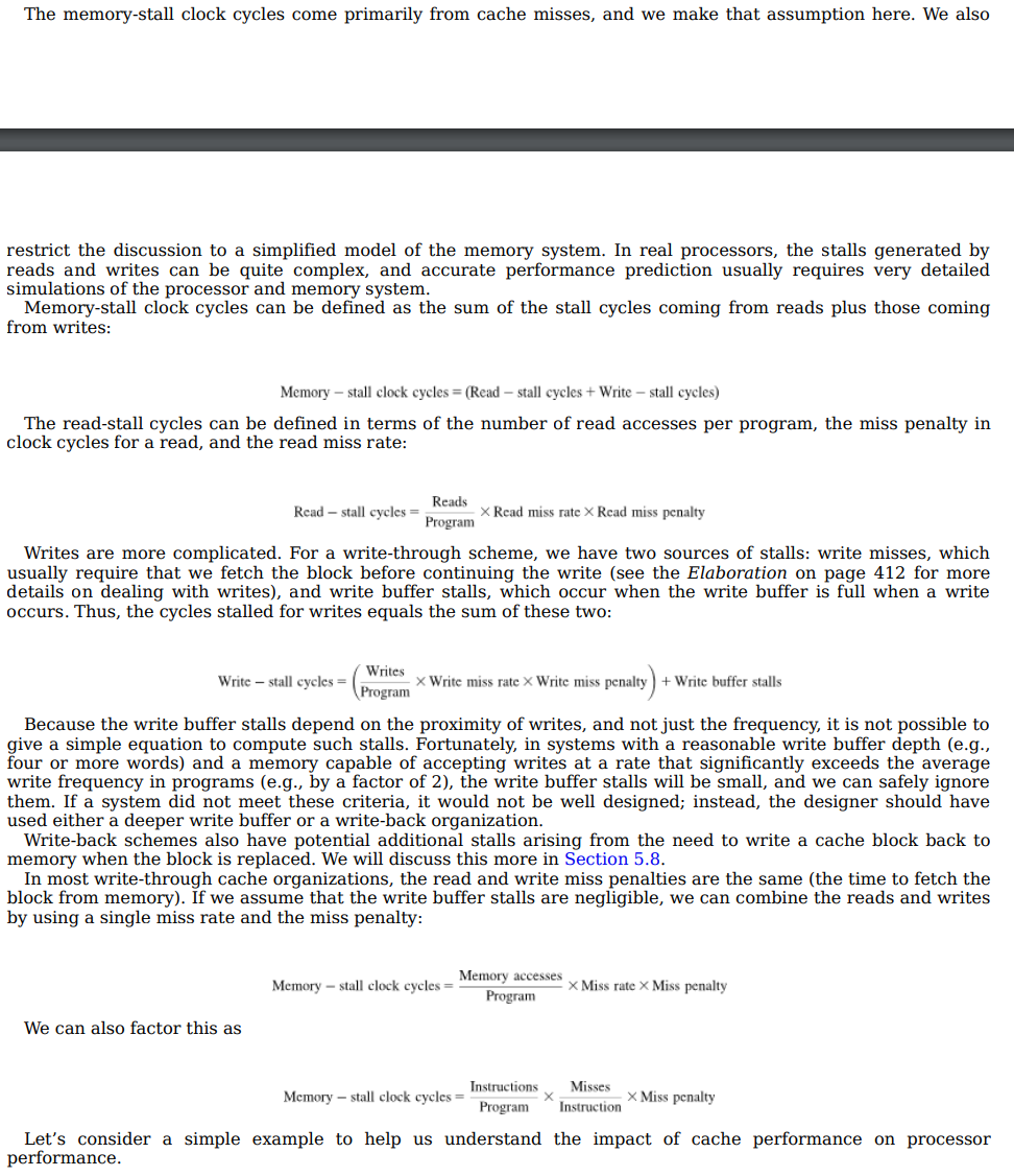
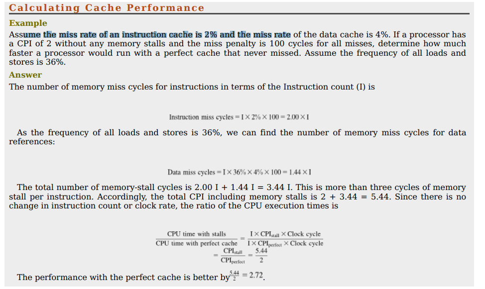
- CPU Time = (CPU execution clock cycles + Memory - stall clock cycles) * Clock cycle time
Multilevel Caches
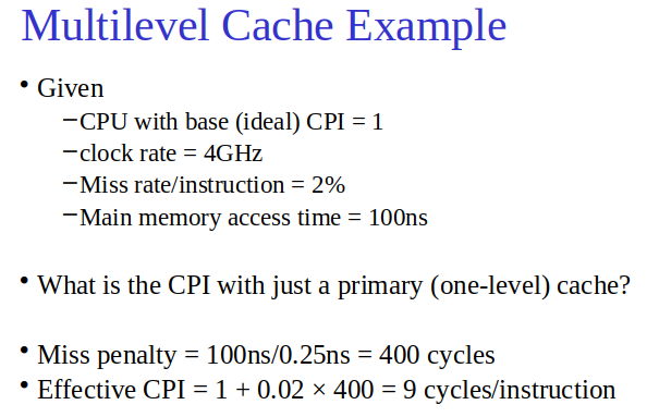
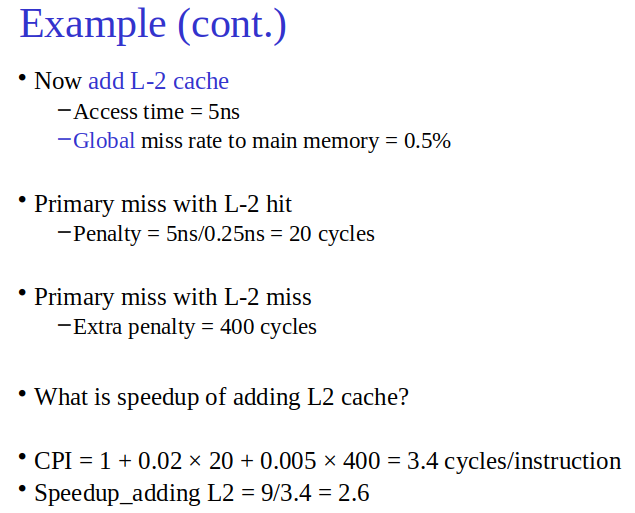
- Secondary Cache: Lowers miss penalty, improving speed significantly.
- Multilevel caches create several complications. First, there are now several different types of misses and corresponding miss rates.
Associativity
Direct Memory Mapping - YouTube
Set Associative Mapping - YouTube
Associative Mapping - YouTube
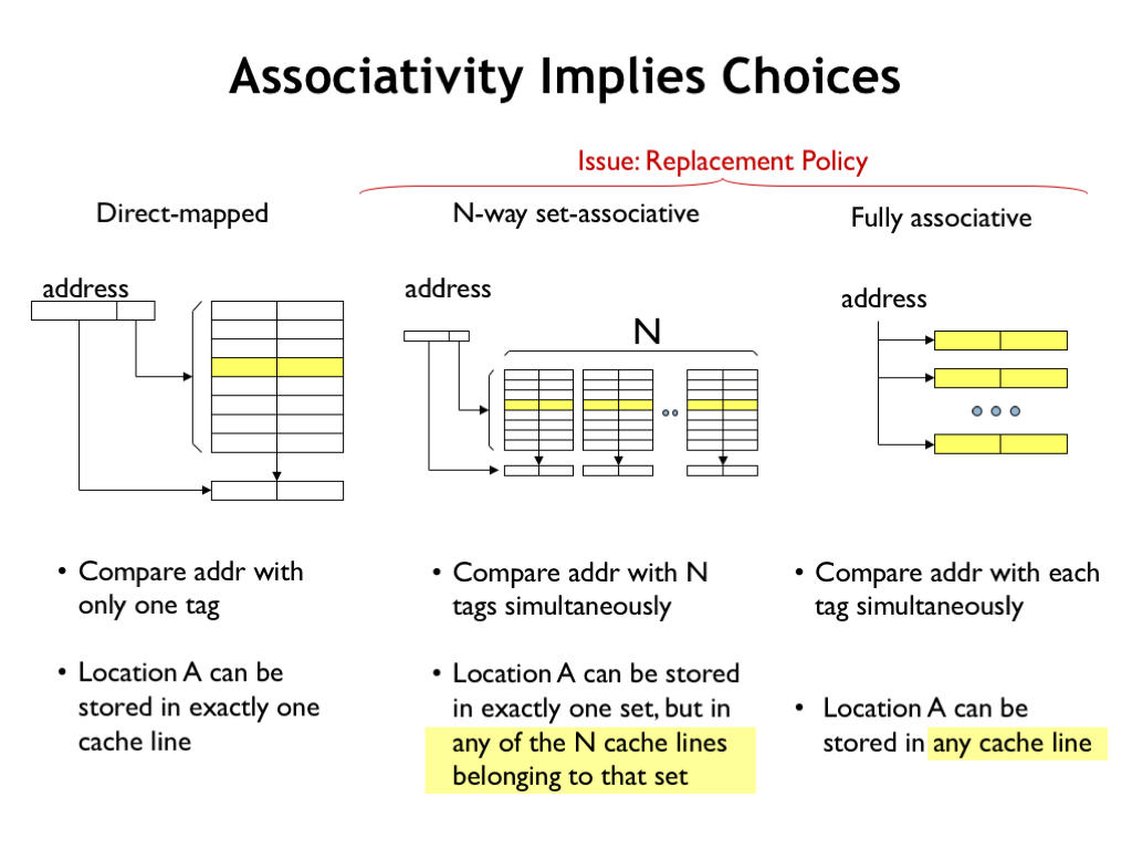
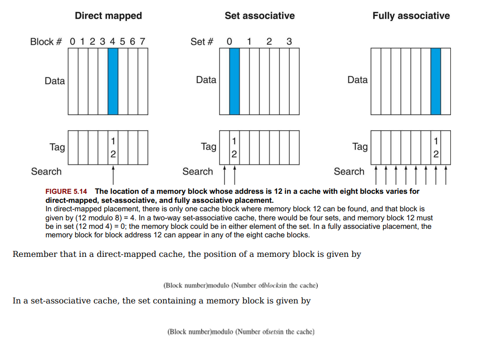
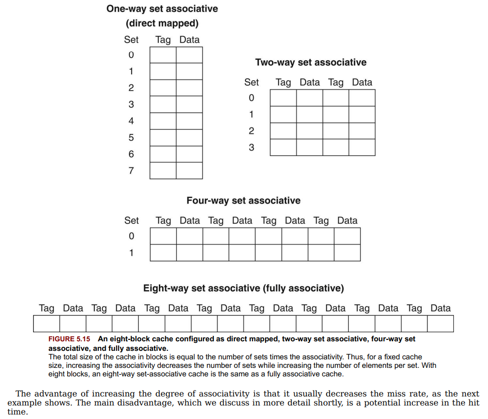
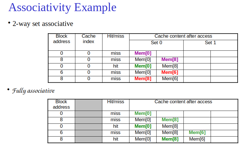
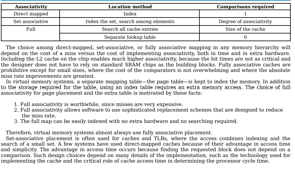
- Direct Mapped: Single location per block.
- Fully Associative: Any location per block. (searched in parallel - hardware cost)
- Set Associative: n locations in a set per block.
- Increases associativity → decreases miss rate but may increase hit time.
Replacement Policies
- LRU (Least Recently Used): Replaces oldest unused block.
Software Optimization
- Blocking: Enhances cache efficiency by operating on submatrices fitting in cache.
Performance Measures
- AMAT = Hit Time + (Miss Rate × Miss Penalty).
- Key: Balance between reducing miss rate and penalty while considering hit time for overall performance.
Virtual Memory
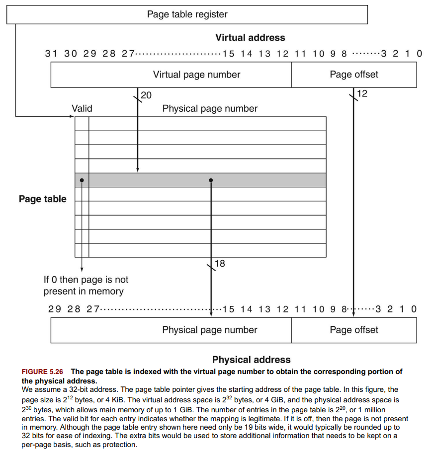
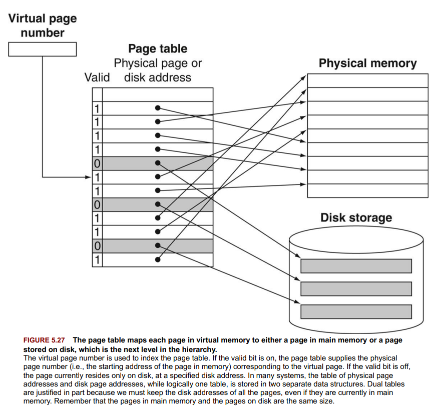
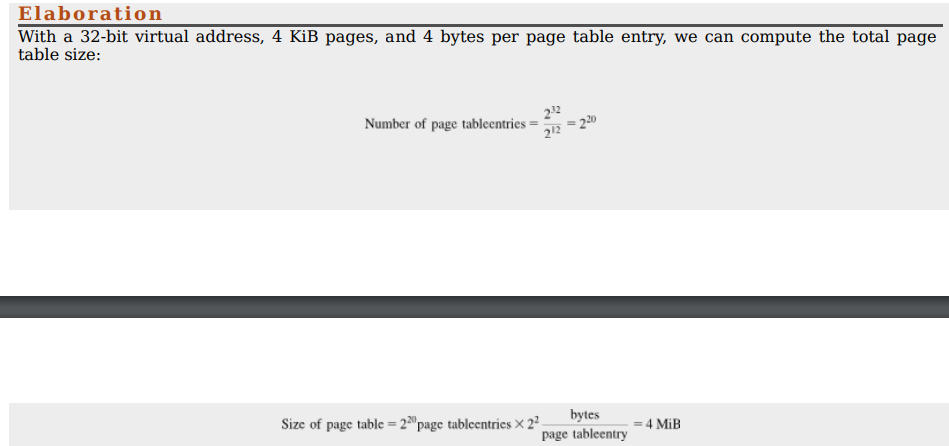
- Virtual Memory (VM): Uses main memory as a cache for secondary storage, supporting process sharing and protection.
- Page: Virtual memory block.
- Page Fault: When an accessed page isn’t in main memory.
- Page Table: Maps virtual addresses to physical, stored in memory.
- TLB (Translation Lookaside Buffer): Cache for page table entries, speeds up address translation.
- Write-Back: Used because disk writes are costly. Dirty bit tracks modified pages.
- most important function of virtual memory today is to allow sharing of a single main memory by multiple processes, while providing memory protection among these processes and the operating system.
Operations
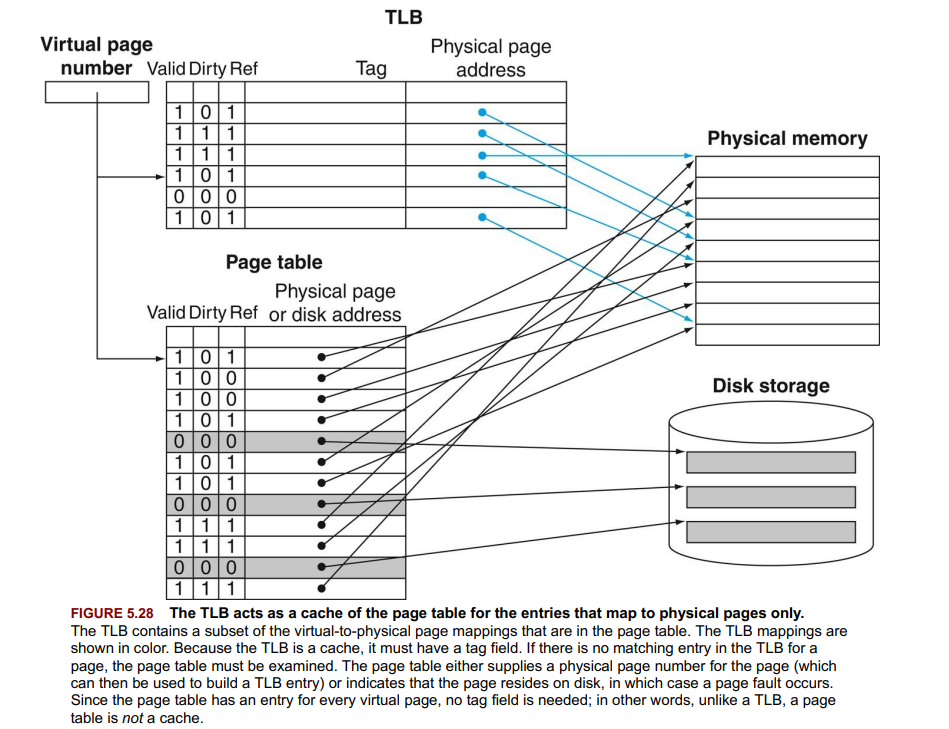
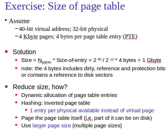
- Address Mapping: Translates virtual to physical addresses via page table.
- Page Fault Handling: OS chooses a physical page to replace, writes it to disk if dirty, loads the requested page.
- TLB Miss: Handled by loading the missing translation from the page table.
- Page Replacement: OS uses strategies like LRU based on access patterns.
Protection
- Ensured via page tables and TLB with permissions.
- Separate page tables per process for isolation.
Performance
- Large Pages: Can reduce faults but increase miss penalty. Variable sizes help optimize access.
- TLB Size/Miss Rate: Critical for performance. High TLB miss rates can significantly impact performance.
Check Yourself Answers
- L1 cache - d. A cache for page table entries
- L2 cache - a. A cache for a cache
- Main memory - b. A cache for disks
- TLB - c. A cache for main memory
What is SIMD ? - YouTube
vector processing
A Common Framework for Memory Hierarchy
-
Block Placement: Direct-mapped, set-associative, fully associative. More associativity = lower miss rate but higher cost/time.
-
Finding Blocks:
- Direct Mapped: 1 comp.
- Set Associative: Search within set.
- Fully Associative: Search all.
-
Block Replacement: Random or LRU. LRU is hard with high associativity, leading to approximations or random choice.
-
Writes:
- Write-Through: Updates all levels, increases traffic.
- Write-Back: Updates on replacement, reduces traffic but complicates design.
-
Three Cs Model:
- Compulsory Misses: First access, can’t be in cache.
- Capacity Misses: Cache too small to hold all data needed.
- Conflict Misses: Multiple data compete for cache space; reduced by increasing associativity.
Key Points:
- Trade-offs in every design choice: associativity vs. speed, capacity vs. access time.
- Fully associative caches eliminate conflict misses.
- Balance between associativity and capacity depends on use case.
Parallelism and Memory Hierarchy: Cache Coherence
- Cache Coherence Issue: Simultaneous access to shared data can lead to inconsistencies across individual processor caches.
- Cache Coherence: Ensures all processors see the same value for shared data to prevent inconsistencies.
- Coherence Definition:
- Reads after a write by the same processor return the written value (preserves program order).
- Reads after a write by another processor return the written value if sufficiently separated in time and no other writes to the data occur between the accesses.
- Writes serialization: Writes to the same location by any processors are seen in the same order by all processors.
- Snooping: Monitors shared medium to maintain coherence; invalidates or updates caches on writes.
- False Sharing: Unrelated variables in the same cache block increase coherence traffic.
- Directory-Based Coherence: Tracks shared data in a central directory for scalability.
- Consistency Models: Dictate when updates to shared data become visible across processors.
MIMD/GPU, Deep Learning and Neural Processing Units, Operating Systems
Topic: Parallel Computing
A process is an instance of a program that is being executed or processed. Thread is a segment of a process or a lightweight process that is managed by the scheduler independently.
Difference between Process and Thread - GeeksforGeeks
Check how to create an IPC and understand the code.
condition code register: difference between x86 and amd.
latency hiding.
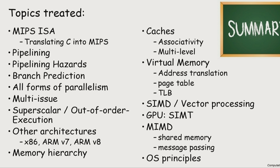
Introduction to Parallel Processors from Client to Cloud
- Multiprocessors improve performance and efficiency.
- Task-Level Parallelism: Different tasks on separate processors.
- Parallel Processing Program: One program, multiple processors.
- Clusters for high-demand tasks, (set of computers connected over a local area network that function as a single large multiprocessor.).
- Multicore: Chips with multiple processors.
- SMP(Shared Memory Processors): Processors share one memory space.
- Goal: Easy, efficient parallel programming.
- Software: Can be sequential or concurrent.
- Hardware: Can be serial or parallel.
- Efficiency critical for multicore use.
The Difficulty of Creating Parallel Processing Programs
Amdahl’s Law - Georgia Tech - HPCA: Part 1 - YouTube
- Parallel programming is harder with more processors.
- Efficiency: Must use multiple processors effectively.
- Challenges: Task splitting, load balancing, sync, communication.
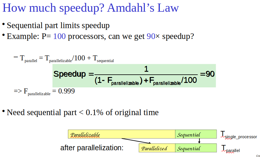
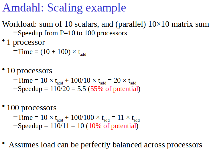
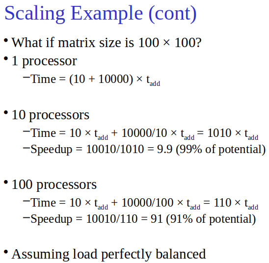
- Amdahl’s Law: Small sequential sections limit speed-up.
Strong vs. Weak Scaling
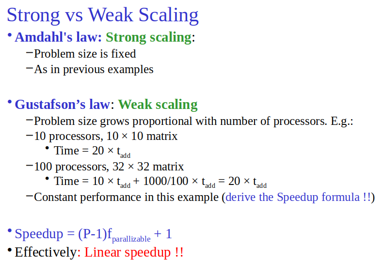
- Strong Scaling: Fixed problem size, harder.(Speed-up achieved on a multiprocessor without increasing the size of the problem)
- Weak Scaling: Problem size grows with processors, easier but depends on memory fit.
Importance of Load Balancing
- Unbalanced load drastically reduces speed-up.
Summary
- Parallelism aims for high performance and energy efficiency.
- Strong scaling limited by Amdahl’s Law.
- Load balancing crucial for utilization and speed-up.
SISD, MIMD, SIMD, SPMD, and Vector
Topic: Parallel Computing
-
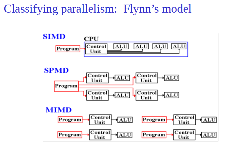
SISD: Single Instruction stream, Single Data stream. Classic uniprocessor.
-
MIMD: Multiple Instruction streams, Multiple Data streams. Standard multiprocessor.
-
SPMD: Single Program, Multiple Data streams. Common MIMD programming model.
-
SIMD: Single Instruction stream, Multiple Data streams. Operations on vectors, like x86 AVX instructions. → a vector architecture.
-
Vector: Uses pipelines or parallel units for vector operations, efficient for data-level parallelism.
-
SIMD and Vector are suited for data parallel tasks.
-
Vector architectures reduce instruction count and improve memory efficiency compared to scalar architectures.
-
Vector operations can handle different data sizes, supporting both contiguous and non-contiguous data access.
-
Modern processors incorporate SIMD for parallel data processing, but vector architectures offer broader capabilities with less instruction overhead.
Hardware Multithreading
- Hardware Multithreading: Enhances processor use by running multiple threads on shared resources.
- Multithreading types aim to maximize processor resource use.
- Thread includes the program counter, the register state, and the stack. It is a lightweight process; whereas threads commonly share a single address space, processes don’t.
- **Process includes one or more threads, the address space, and the operating system state. Hence, a process switch usually invokes the operating system, but not a thread switch.
Types
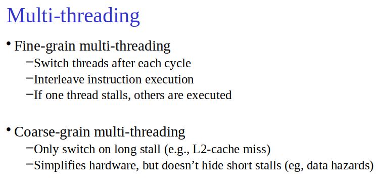
- Fine-Grained: Swaps threads each cycle to hide stalls.
- Coarse-Grained: Switches threads on major stalls like cache misses.
- Simultaneous (SMT): Runs multiple threads per cycle, leveraging instruction-level parallelism for higher throughput.
Benefits
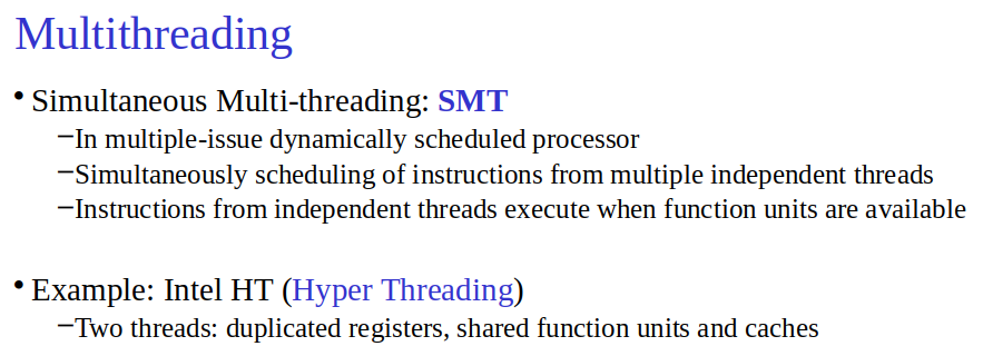
- SMT notably improves performance and energy efficiency by filling idle slots with instructions from various threads, making it highly effective on modern processors. (effective in out of order execution OOT)
Multicore and Other Shared Memory Multiprocessors (SMP)
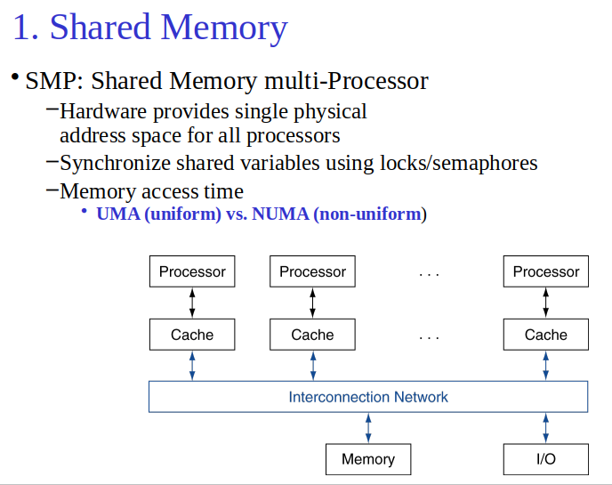
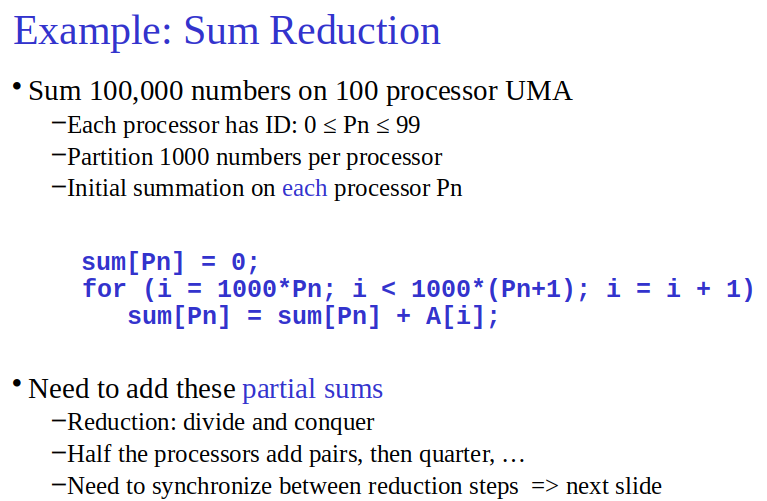
- SMP: Offers a single physical address space for all processors, easing data access in parallel programming.
- SMP Types:
- UMA: Uniform Memory Access.
- NUMA: Nonuniform Memory Access, variable access times based on processor-memory proximity.
- Synchronization: Essential for parallel data access; typically managed via locks.
- Example: Summing 64,000 numbers with 64 processors involves data partitioning and a reduction phase for the final sum.
- OpenMP: An API for simplified parallel programming in shared memory environments. Use
cc –fopenmp foo.cfor C compilation. - Key Points:
- SMPs share a physical address space for easier parallel programming.
- Proper synchronization ensures data consistency across processors.
- OpenMP aids in loop parallelization and data reduction in SMPs.
Introduction to Graphics Processing Units
Topic: Parallel Computing
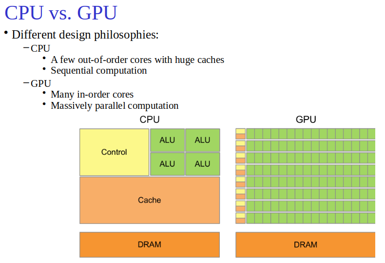
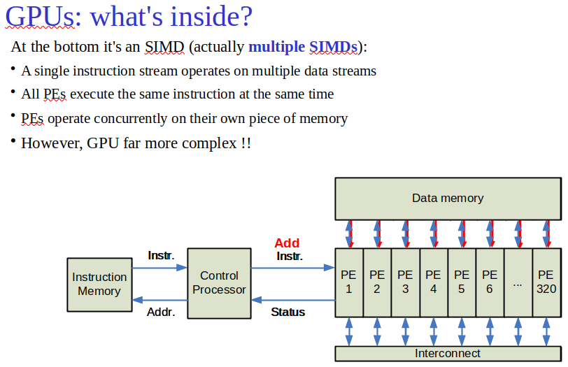
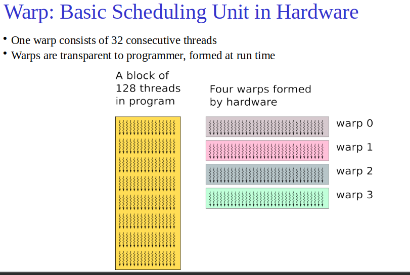
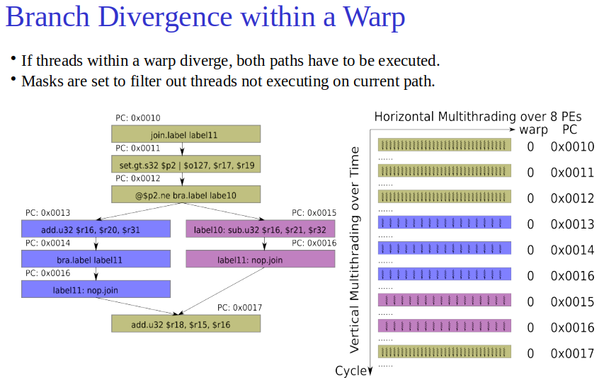
- GPUs vs CPUs: GPUs focus on parallel processing for graphics; CPUs handle diverse tasks. GPUs use multithreading and high-bandwidth memory; CPUs use caches for memory efficiency.
- PE - processing elements
- Memory: GPUs optimize for bandwidth, relying on hardware multithreading to manage memory latency. CPUs use hierarchical caching for latency management.
- Architecture: GPUs are built for massive parallelism with many threads and processors. CPUs balance between core performance and multitasking efficiency.
- Programming: CUDA and OpenCL enable GPGPU, allowing GPUs to perform general computing tasks beyond graphics.
- Differences:
- GPUs use hardware multithreading extensively.
- GPUs’ memory system is designed for high throughput over low latency.
- Architecturally, GPUs are MIMD with multithreaded SIMD processors.
- Use Cases: GPUs are preferred for tasks requiring high parallelism like graphics, gaming, and some computing tasks. CPUs are versatile, suitable for a wide range of applications.
Biggest difference is that GPUs do not rely on multilevel caches to overcome the long latency to memory, as do CPUs. Instead, GPUs rely on hardware multithreading to hide the latency to memory.
Introduction to Multiprocessor Network Topologies
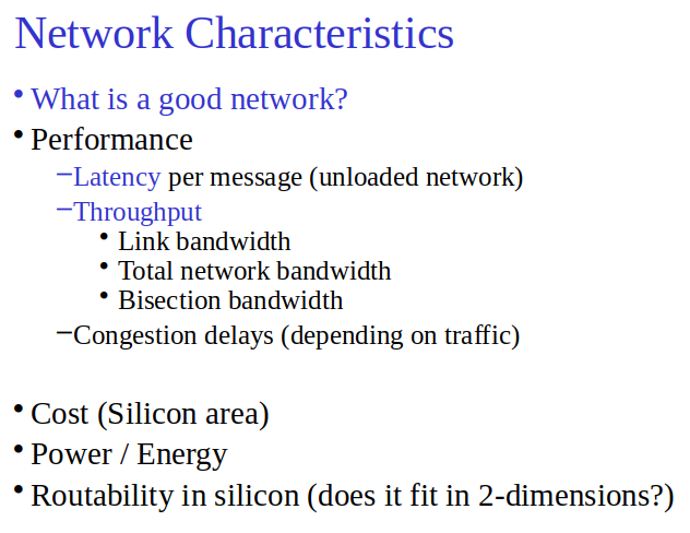
- Costs: Determined by switches, links, and their lengths.
- Performance: Measured by latency, throughput, and how contention affects traffic.
Key Topologies
- Ring: Connects nodes in a loop. Efficient for simultaneous transfers but requires message hopping.
- Fully Connected: Direct connection between all nodes. Offers high performance but is expensive.
Bandwidth Concepts
- Total Bandwidth: Product of link bandwidth and the number of links.
- Bisection Bandwidth: Minimum bandwidth when the network is split into two equal parts. Indicates worst-case performance.
Popular Designs
- Multistage: Uses switches at nodes for denser, more efficient communication.
- Boolean n-cube & Crossbar: Support efficient, though potentially costly, direct communication paths between nodes.
- Omega: Lower hardware need but susceptible to message contention.
Practical Aspects
- Link Distance: Longer links increase costs and reduce performance.
- Physical Mapping & Energy: Real-world constraints and energy efficiency critically influence topology choice.
Real Stuff: Benchmarking the Google TPUv3 Supercomputer and an NVIDIA Volta GPU Cluster
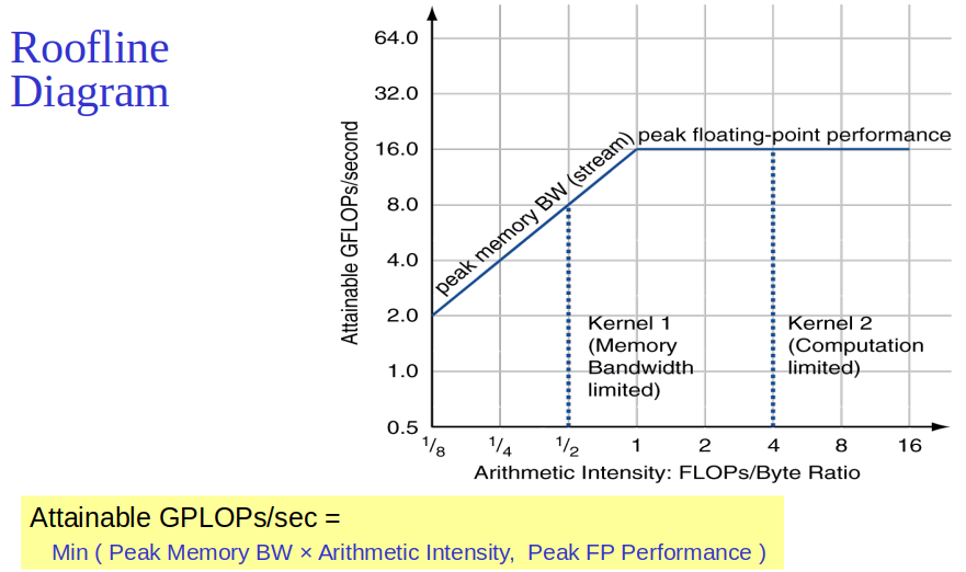
optimixation depends on arithmetic intensity.
- DNN Phases: Forward propagation, back-propagation, weight updates.
- TPUv3 Features:
- Inter-Core Interconnect (ICI) for chip communication.
- High Bandwidth Memory (HBM) for faster data access.
- Dual-Core with Matrix Multiply Unit (MXU) for DNN calculations.
- bf16 Arithmetic Format optimized for DNN precision and performance.
- Architecture Comparison:
- TPUv3: Multichip parallelization, bf16 arithmetic, software-controlled memories.
- NVIDIA Volta: fp16 arithmetic, hardware-managed memory, requires software for loss scaling.
- Costs: TPUv3 shows lower costs and higher energy efficiency than NVIDIA Volta.
- Performance:
- Comparable on benchmarks; TPUv3 excels in Google’s production DNN applications.
- TPUv3 achieves near-linear scaling and superior energy efficiency in supercomputing tasks.
Summary
- TPUv3 is tailored for DNN training, offering efficient computation, scalability, and energy use. It stands out in handling complex DNN models, showing cost and performance advantages over traditional GPUs.
Going Faster: Multiple Processors and Matrix Multiply
- Optimization: Added OpenMP pragma to parallelize DGEMM.
- Core Usage: Utilized 48 cores.
- Performance:
- Small matrices: Performance decreases with more threads.
- Large matrices: Up to 17x speedup with 48 threads.
- Improvements:
- Original C version: 2 GFLOPS.
- Optimized version (960x960): 308 GFLOPS.
- Speedup from C to optimized: ~150x.
- Speedup from Python to optimized C: ~50,000x.