Resit notes for Computation II - 5EIB0

RISC-V (little endian)

Topic: Instruction Set Architecture

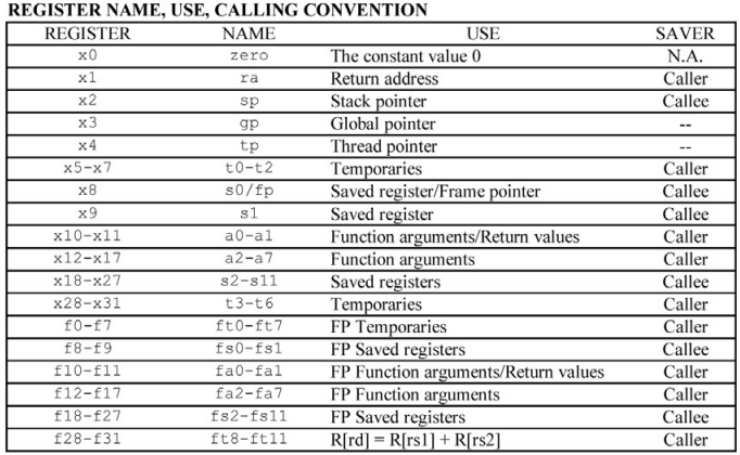
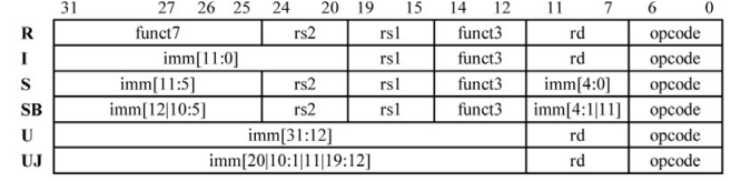
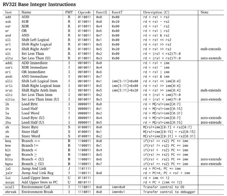
RISC-V-Reference-Data.pdf

6/7 great ideas in CA:

  1. Abstraction
  2. Common case faster
  3. Memory hierarchy
  4. Parallelism (serial is bottleneck → Amdahl’s law) + Pipelining
  5. Performance measurement and improvement
  6. Dependability via Redundancy

Design principle:

  1. Simplicity favors regularity → operations have 2-3 operands
  2. Smaller is faster → 32 registers
  3. Good design demands good compromises → similar instruction format >> more byte

Instructions (resit) - 5EIB0

Resit notes for Computation II - 5EIB0

Procedure Call

Untitled

RISC

%

%

Memory: lw (load), sw (store)
Byte memory: lbu (load byte unsigned), sb
Arithmetic: add, addi, sub, mul

  • Binary arithmetic:
    • AND: select range of bits
    • OR: set to 1
    • XOR: with 111….. to invert

Conditional branch: beq (=), bne (≠), (unsigned) (blt (<), bge (≥))

Call: jal (jump and link, use immediate address → caller), jalr (jump and link register, use indirect address → callee)

  • Notes:

    • No sbu, ble, bgt, NOT
    • (S)B ≠ S format ← 1st bit of immediate is always 0 (byte address)← instructions can only be multiples of 16 bits
    • jalr immediate don’t assume 1st bit is 0 (because it use I-type) → reduce range
    • jaddi with top bit = 1 will -1 from 20 upper bits (due to sign extension)
  • Steps to call function:

    1. Prologue: Put arguments in a place (registers) where function can access them
    2. Transfer control to function (jal)
    3. Acquire (local) storage resources needed for function
    4. Perform desired task of the function
    5. Put return value in a place where calling code can access it and restore any registers you used; release local storage
    6. Epilogue: Return control to point of origin, since a function can be called from several points in a program (ret)
int fact (int n)
{
if (n < 1) return (1);
else return (n * fact(n − 1));
}
fact:
//prologue 
addi sp, sp, -8 // adjust stack for 2 items
sw x1, 4(sp) // save the return address
sw x10, 0(sp) // save the argument n
 
addi x5, x10, -1 // x5 = n - 1
bge x5, x0, L1 // if (n - 1) >= 0, go to L1
 
addi x10, x0, 1 // return 1
addi sp, sp, 8 // pop 2 items off stack
jalr x0, 0(x1) // return to caller
 
L1: addi x10, x10, -1 // n >= 1: argument gets (n − 1)
jal x1, fact // call fact with (n − 1)
 
//epilogue
addi x6, x10, 0 
// return from jal: move result of fact (n - 1) to x6:
lw x10, 0(sp) // restore argument n
lw x1, 4(sp) // restore the return address
addi sp, sp, 8 // adjust stack pointer to pop 2 items
 
mul x10, x10, x6 // return n * fact (n − 1)
jalr x0, 0(x1) // return to the caller
  1. Immediate addressing, where the operand is a constant within the instruction itself
  2. Register addressing, where the operand is a register
  3. Base or displacement addressing, where the operand is at the memory location whose address is the sum of a register and a constant in the instruction
  4. PC-relative addressing, where the branch address is the sum of the PC and a constant in the instruction
  5. Pseudodirect addressing, where the jump address is the 26 bits of the instruction concatenated with the upper bits of the PC

Compiler (resit) - 5EIB0

Floating Point (resit) - 5EIB0

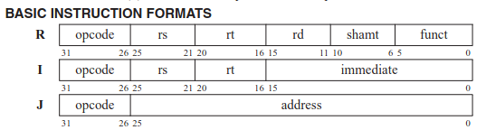
MIPS

%

op: opcode
rs: first input
rt: second input
rd: output
shamt: shift amount
funct: function code

ARM V7

Instructions:

ARM addressing modes:

ARM V8

X86 Intel/AMD

Encoding
Addressing modes:

Link to original

Cache (resit) - 5EIB0

Resit notes for Computation II - 5EIB0

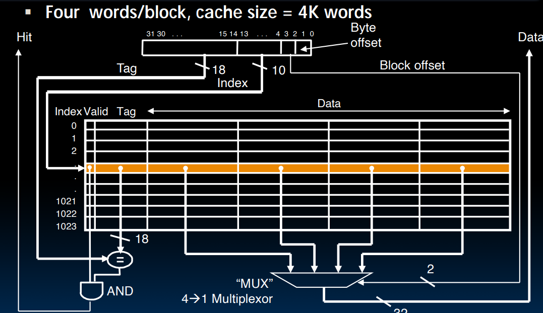
Cache

Spatial + Temporal locality

Direct Mapped Cache:

Lowest addressable unit is a byte (8 bit ??) nibble 4 bit
Byte offset: 2 bit (for 32-bit arch)

Cache index = MM index % n0 of cache max index

Average memory access time (AMAT):

Write hit:

  • Write through: update both cache and memory
  • Write-back:
    • update in cache only → memory can be “stale”
    • add dirty bit to → check if data is updated to memory → update when cache block is flushed

Cache misses: compulsory → capacity → conflict

  • D-cache (data): only in load & store instructions
  • I-cache (instruction)

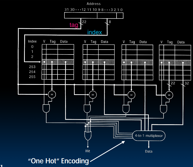
N-way Associative Cache

Direct-mapped with N block sets → can be mapped to any block within sets
Set index = MM index % n0 of sets
N = n0 of cache blocks → fully associative

Fix address aliasing

Cache block size = 2^(n0 of byte offset bits) bytes
N0 of cache entries = 2^(n0 of index bits)
Cache size = (1 valid bit (+ 1 dirty bit for write-back) + tag + cache block size) * n0 of cache entries

T_spdup = (CPI_ideal + factor * CPI_stall) * T_clk / factor

Link to original

Processor Design (resit) - 5EIB0 > Datapath

Processor Design (resit) - 5EIB0

Resit notes for Computation II - 5EIB0

Datapath

Add/sub (R): PC + Adder + IMEM + Reg + ALU

Immediate: (I) + ImmGen + Mux (R[rs2] - ALU)

Load/store: + DMEM + Mux (DMEM DataB - DataD Reg)

Branch/jump: + Mux (ALU - PC) + Mux (PC - ALU) + BranchComp
→ Critical path (slowest) is lw (~800 ps)→ Pipelining

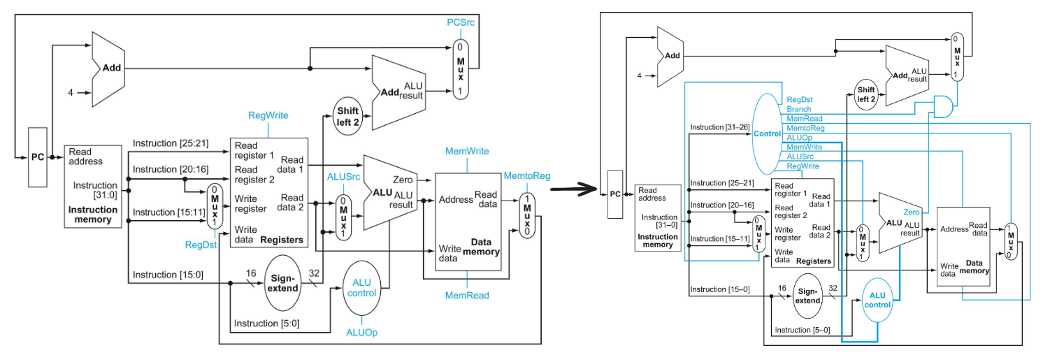
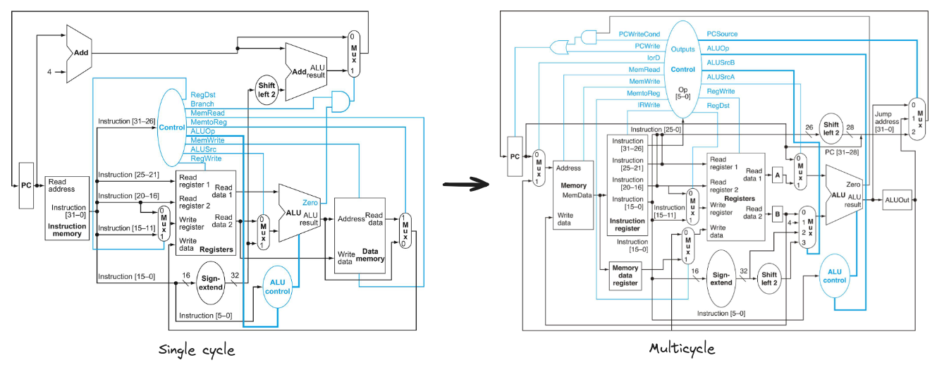
Single-cycle

%

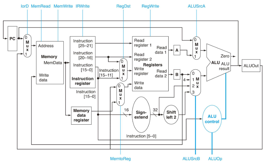
Multicycle

%
Single cycle → Multicycle: instructions separated into stages

  • Separate memory unit for instructions + data → need memory data access for ALU
  • 1 ALU + 2 adders → 1 ALU
  • Store values of every stage:
    • Instruction Register (IR) & Memory data register (MDR) added
    • A & B for operand values
    • ALUOut for ALU output
  • ALU:
    • ALU input 1: PC | A
    • ALU input 2: + Shift left (branch address) | 4 (increment PC)
    • Jump and branch output:
      • ALU output (PC+4)
      • ALUout
      • The lower 26 bits of the Instruction register (IR) shifted left by two and concatenated with the upper 4 bits of the incremented PC, which is the source when the instruction is a jump

Control Signal

%

Signal nameEffect when deassertedEffect when asserted
RegDstWrite register = rtWrite register = rd
RegWriteNone.The general-purpose register selected by the Write register number is written with the value of the Write data input.
ALUSrcAThe first ALU operand is the PC.The first ALU operand comes from the A register.
MemReadNone.Content of memory at the location specified by the Address input is put on Memory data output.
MemWriteNone.Memory contents at the location specified by the Address input is replaced by the value on the Write data input.
MemtoRegWrite data = ALUOutWrite data = MDR
IorDAddress = PCAddress = ALUOut
IRWriteNone.IR = memory output
PCWriteNone.The PC is written; the source is controlled by PCSource.
PCWriteCondNone.The PC is written if the Zero output from the ALU is also active.
Signal nameValue (binary)Effect
ALUOp00The ALU performs an add operation.
01The ALU performs a subtract operation.
10The funct field of the instruction determines the ALU operation.
ALUSrcB00The second input to the ALU comes from the B register.
01The second input to the ALU is the constant 4.
10The second input to the ALU is the sign-extended, lower 16 bits of the IR.
11The second input to the ALU is the sign-extended, lower 16 bits of the IR shifted left 2 bits.
PCSource00Output of the ALU (PC + 4) is sent to the PC for writing.
01The contents of ALUOut (the branch target address) are sent to the PC for writing.
10The jump target address (IR[25:0] shifted left 2 bits and concatenated with PC + 4[31:28]) is sent to the PC for writing.

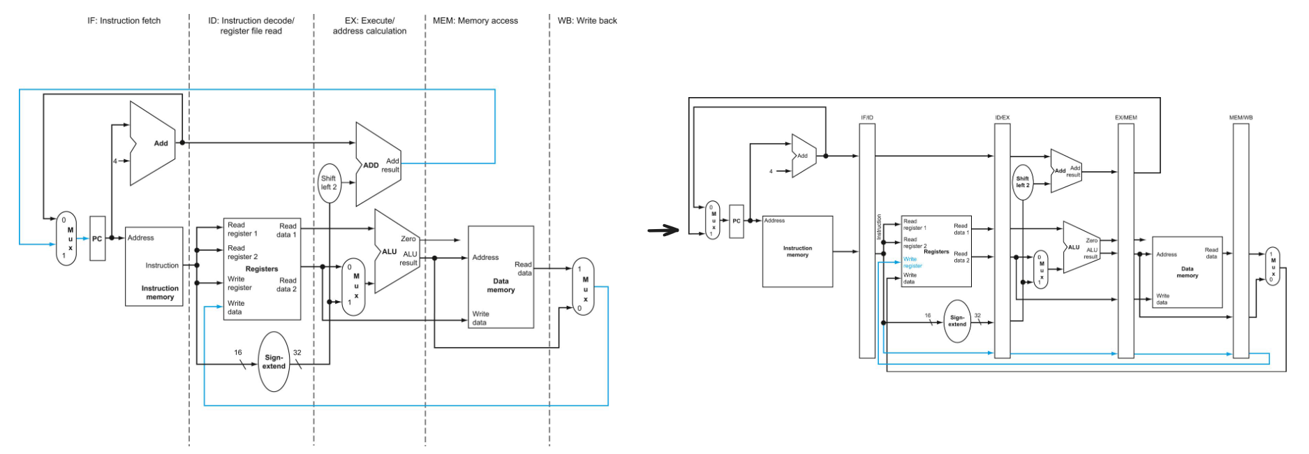
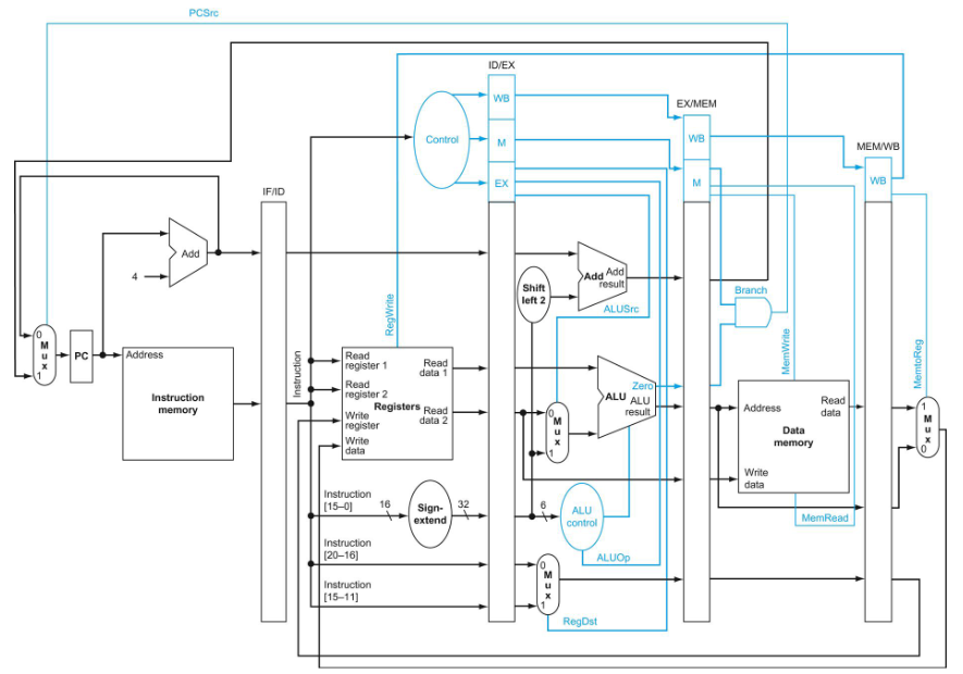
Pipelined

Instructions separated into like Multicycle but multiple stages can be active simultaneously

  1. Instruction Fetch (IF): Fetch instruction + increment PC
  2. Instruction Decode (ID): Decode instruction + Get operands (+ Branch decision + target)
  3. Execute (EX): ALU (Arithmetic-Logic Unit)
  4. Memory Access (MEM): store or load mem
  5. Write Back to Register (WB)
    %
    !! load instructions need to calculate write register → pipeline write register

Control Signal

%

Signal nameEffect when deasserted (0)Effect when asserted (1)
RegDstThe register destination number for the Write register comes from the rt field (bits 20:16).The register destination number for the Write register comes from the rd field (bits 15:11).
RegWriteNone.The register on the Write register input is written with the value on the Write data input.
ALUSrcThe second ALU operand comes from the second register file output (Read data 2).The second ALU operand is the sign-extended, lower 16 bits of the instruction.
PCSrcThe PC is replaced by the output of the adder that computes the value of PC + 4.The PC is replaced by the output of the adder that computes the branch target.
MemReadNone.Data memory contents designated by the address input are put on the Read data output.
MemWriteNone.Data memory contents designated by the address input are replaced by the value on the Write data input.
MemtoRegThe value fed to the register Write data input comes from the ALU.The value fed to the register Write data input comes from the data memory.

Pipelining Considerations

Hazards:

  • Structural
  • Data
  • Control

Structural Hazard: Occupied Physical Resource

Multiple instructions compete for physical resources → stall/ more resources

Instruction and data mem used simultaneously → use seperate I/D mem → I/D cache

Data Hazard: Simultaneous read/write

Register read+write access: can be solved if using single cycle read-write

ALU result hazard:

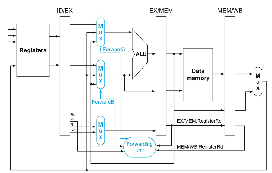
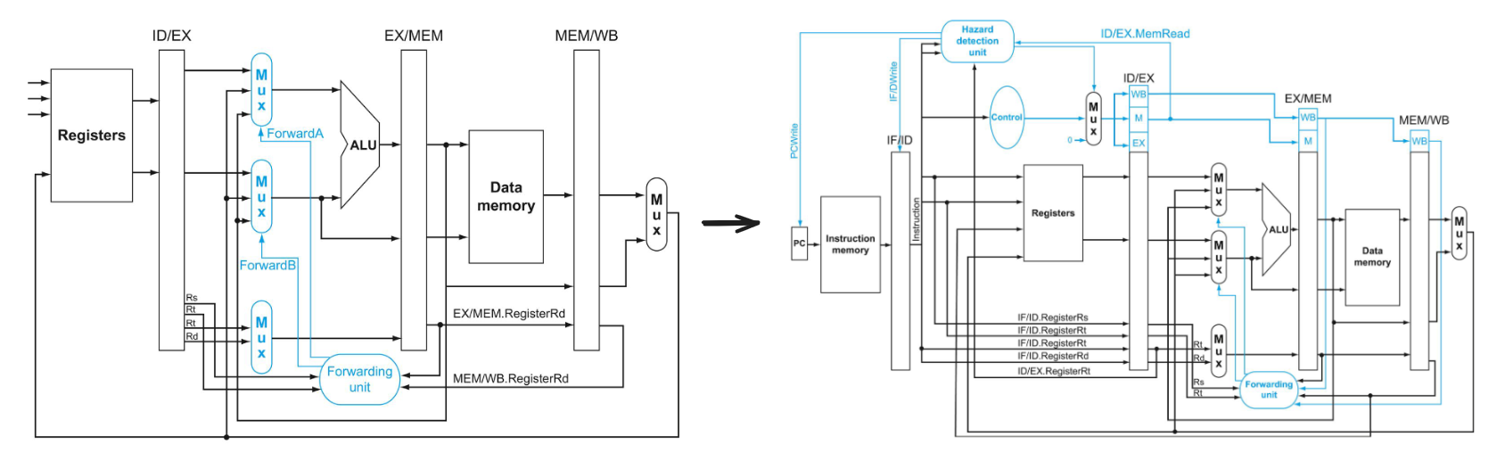
Forwarding (bypassing)

use result from ALU directly (b4 storing in registers) → need extra connections
%

if (EX/MEM.RegWrite 
and (EX/MEM.RegisterRd ≠ 0) 
and (EX/MEM.RegisterRd = ID/EX.RegisterRs)) ForwardA = 10

if (MEM/WB.RegWrite 
and (MEM/WB.RegisterRd ≠ 0) 
and not(EX/MEM.RegWrite and (EX/MEM.RegisterRd ≠ 0) 
and (EX/MEM.RegisterRd ≠ ID/EX.RegisterRs)) 
and (MEM/WB.RegisterRd = ID/EX.RegisterRs)) ForwardA = 01

No forwarding if Rd=0
Don’t forward from WB if already forwarded from MEM

Stall (insert nops)

%

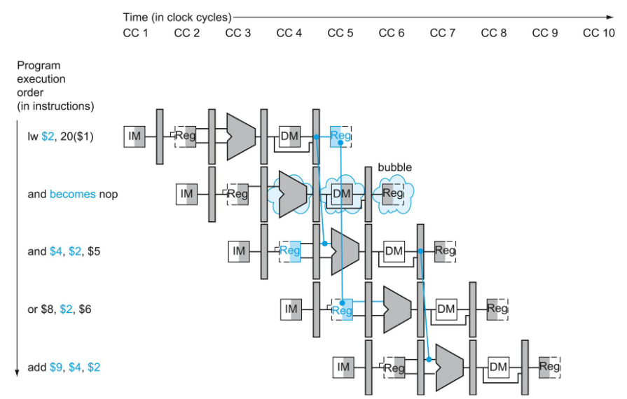
  • Load-use hazard: 1 cycle stall (MEM to EX) → nops/rearrange code = set control signals in EX, MEM, WB stages to 0
  • Load-branch hazard: 2 cycle stall (MEM to IF) (with Branch speedup)
if (ID/EX.MemRead and
((ID/EX.RegisterRt = IF/ID.RegisterRs) or
(ID/EX.RegisterRt = IF/ID.RegisterRt)))

%

Control Hazard

Branch undetermined: convert 2 stall cycles + branch prediction

Branch Speedup

Calculate address and condition earlier at ID
→ Can only implement beq|bneq (others require 1 more calculation instructions) + Load-branch hazard

Branch Prediction

Branch prediction = predict of branch is taken != Branch target prediction = predict branch address
Static:

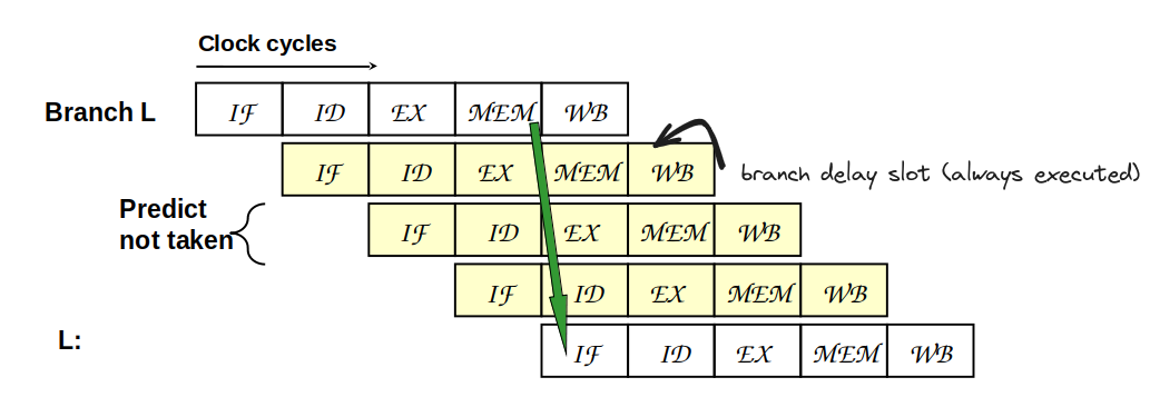
  • Default = progress (assume branch not taken) → execute branch delay slot → flush IR if branch taken
    %
    Dynamic
  • Branch predictor#Saturating_counter :strictly based on previous outcomes if branch taken (1 or 2 bit (takes 2 wrong prediction to change))
  • Branch predictor#Two-level_predictor
  • Local prediction: correlate with previous outcomes
  • Global prediction: correlate with all branches
  • Local + global

Load delay + Branch delay

RISC-V ISA designed for pipelining:

  • All instructions are 32-bits
  • Easy to fetch and decode in one cycle
  • Versus x86: 1- to 15-byte instructions
  • Few and regular instruction formats
  • Decode and read registers in one step
  • Load/store addressing
  • Alignment of memory operands
  • Memory access takes only one cycle
Link to original

Related Concepts