5XTC0 Components in Wireless Technologies
- Area: Electromagnetics and Waves
- Topics: Noise · Transmission Lines · Antennas and Radiation · S-Parameters and Impedance Matching · Wireless Channel
- Related courses: Electromagnetics II - 5EPB0 · Communication 1 - 5ETC0 · Bachelor End Project - BEP
Schedule


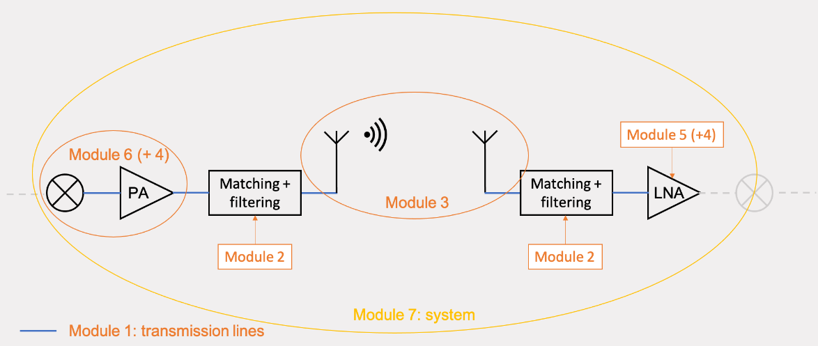
Overview
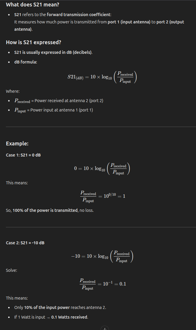
S-Parameters for Antennas (S11, S12, …)
Transmission Lines
Topic: Transmission Lines
5XTC0_Lecture_Module1_TL-Theory_2025.pdf
Formulas
Telegrapher Equations (Time Domain):
Telegrapher Equations (Frequency Domain):
Wave Equations (Voltage and Current):
whereGeneral Solution (Wave Propagation):
Characteristic Impedance:
For lossless lines:Lossless Line Parameters:
Reflection Coefficient at Load:
Voltage and Current on Terminated Line:
Input Impedance at Distance
from Load:
Quarter-Wave Transformer Matching Condition:
if line lengthTransmission Coefficient:
Insertion Loss (dB):
Smith Chart Reflection Phase Relation:
other
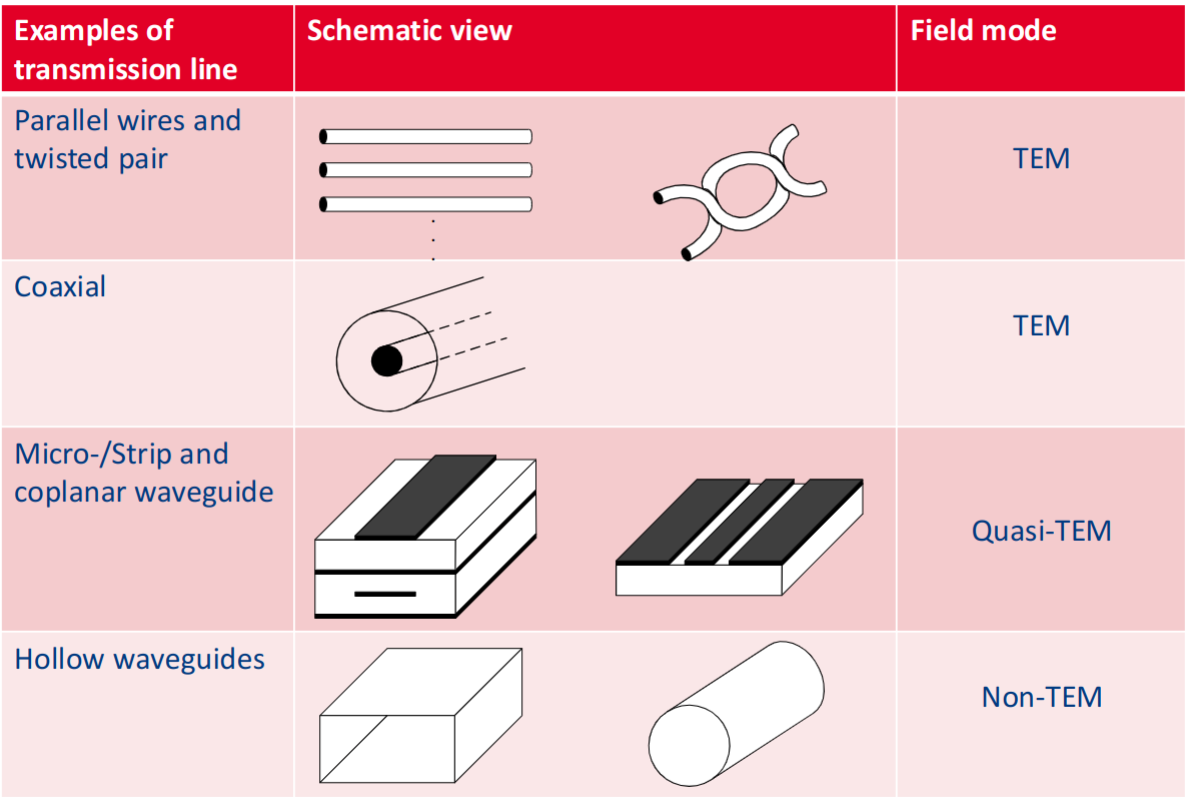
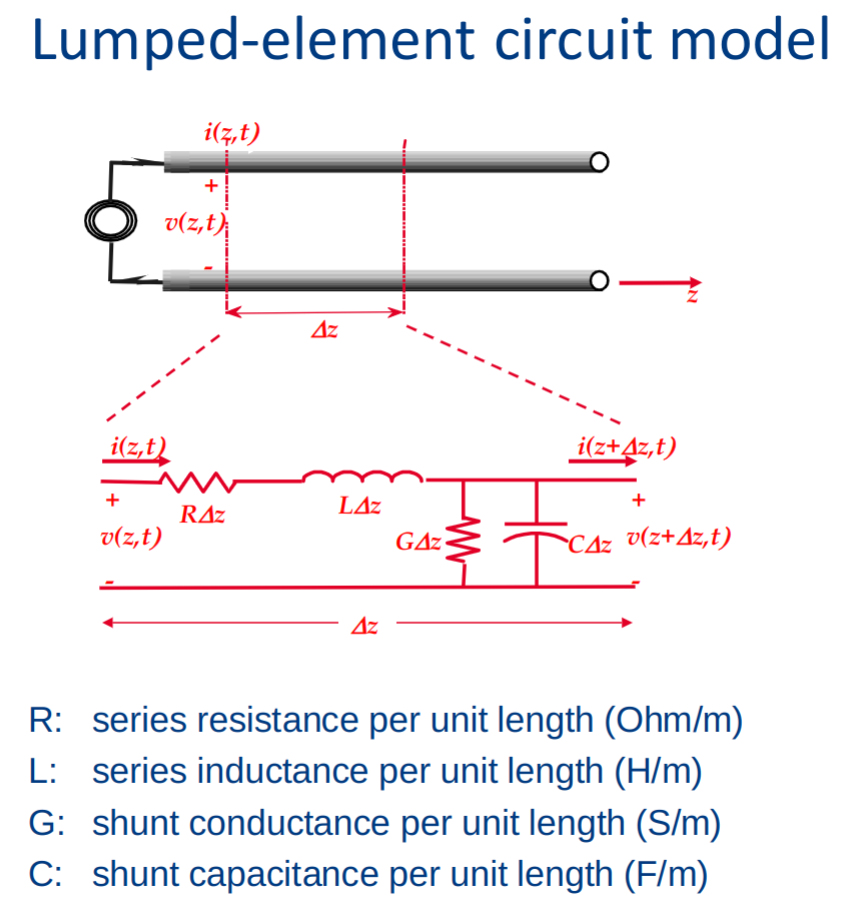
Telegrapher equations
KVL and KCL:
Time domain:
Frequency domain:
Wave propagation on a transmission line
solving the above further the telegraph equations produce:
complex propagation constant:
Wave propagation on Tline
The voltage and current along a transmission line can be expressed as the sum of forward and backward traveling waves:
Derivation of the Voltage Equation
The spatial derivative of voltage along the transmission line is given by:
Using the Telegrapher’s equations, this is also equal to:
Substituting
:
Expressing Current Components in Terms of Voltage
From the above equation, we can solve for
and :
Characteristic Impedance of the Transmission Line
The ratio of voltage to current defines the characteristic impedance:
is the characteristic impedance of the transmission line, which determines how waves propagate and reflect along the line.
The lossless transmission line
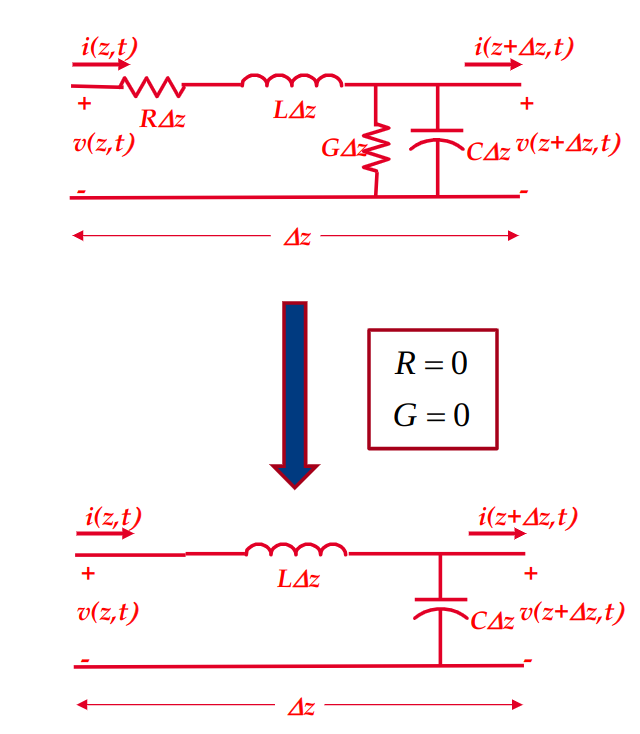
Total voltage and current:
Total voltage and current at the load at
Special cases:
short circuit load:
Rewriting:
Terminated Transmission Line Equations
connected a resistance at the end of transmission line, so pulse sees same impedance at the end as it did propagating.
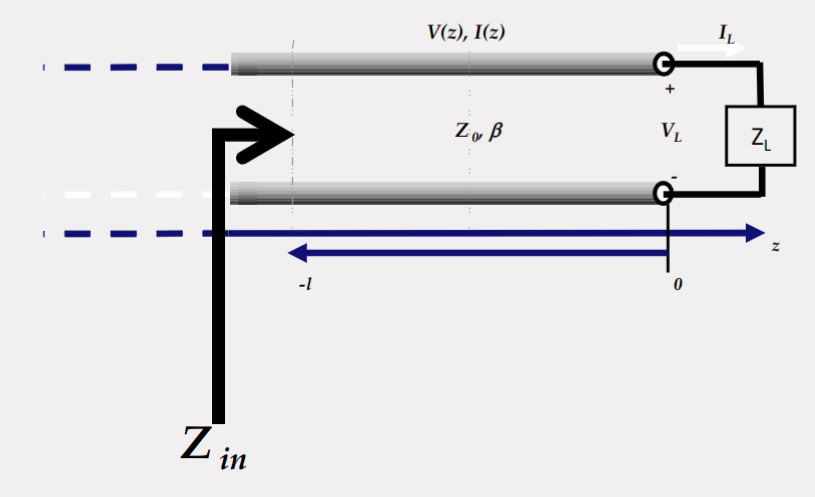
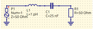
LC lumped element (resonator) as load:
Insertion Loss
Insertion loss quantifies the power loss when two transmission lines with different characteristic impedances are connected.
Transmitted Wave for
:
whereis the transmission coefficient. Transmission Coefficient:
This equation determines how much of the wave is transmitted through the junction.Insertion Loss (IL):
Insertion loss is calculated using power ratios:
Simplifying:
The negative sign indicates loss in power transmission. A higher impedance mismatch leads to greater insertion loss.
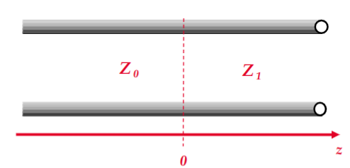
Quarter-Wave Transformer – The Impedance Viewpoint
The quarter-wave transformer is a transmission line segment of length
used to match two impedances. Input Impedance at
: The impedance transformation equation is given by:
Special Case for a Quarter-Wavelength Line:
Since the phase shift
for a quarter-wavelength section is:
The input impedance simplifies to:
Transmission line length:
Condition for Perfect Matching:
To achieve impedance matching (
), we set:
This ensures that all power is transferred to the load without reflections.
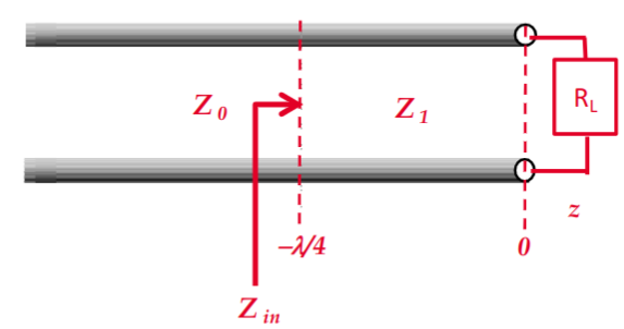
quarter wave transformer:
Thus,
In our case,
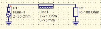
Lossy quarter wave transformer:
Smith chart
Topic: Transmission Lines
The scariest thing you learn in Electrical Engineering | The Smith Chart - YouTube
- When there is very high frequencies on small length it causes reflections, good example in the video with a pulsating rope.
- Smith chart shows how much Voltage transmitted vs how much is reflected.
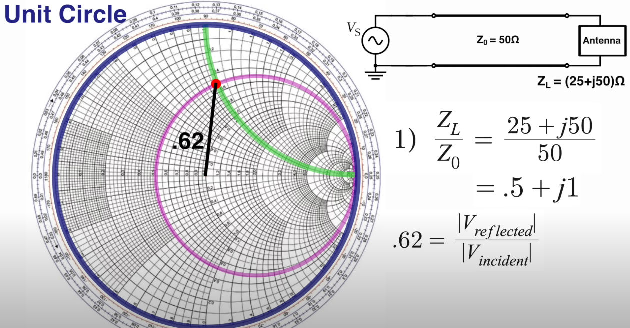
if the original signal is 10V then the reflection is 6.2V.
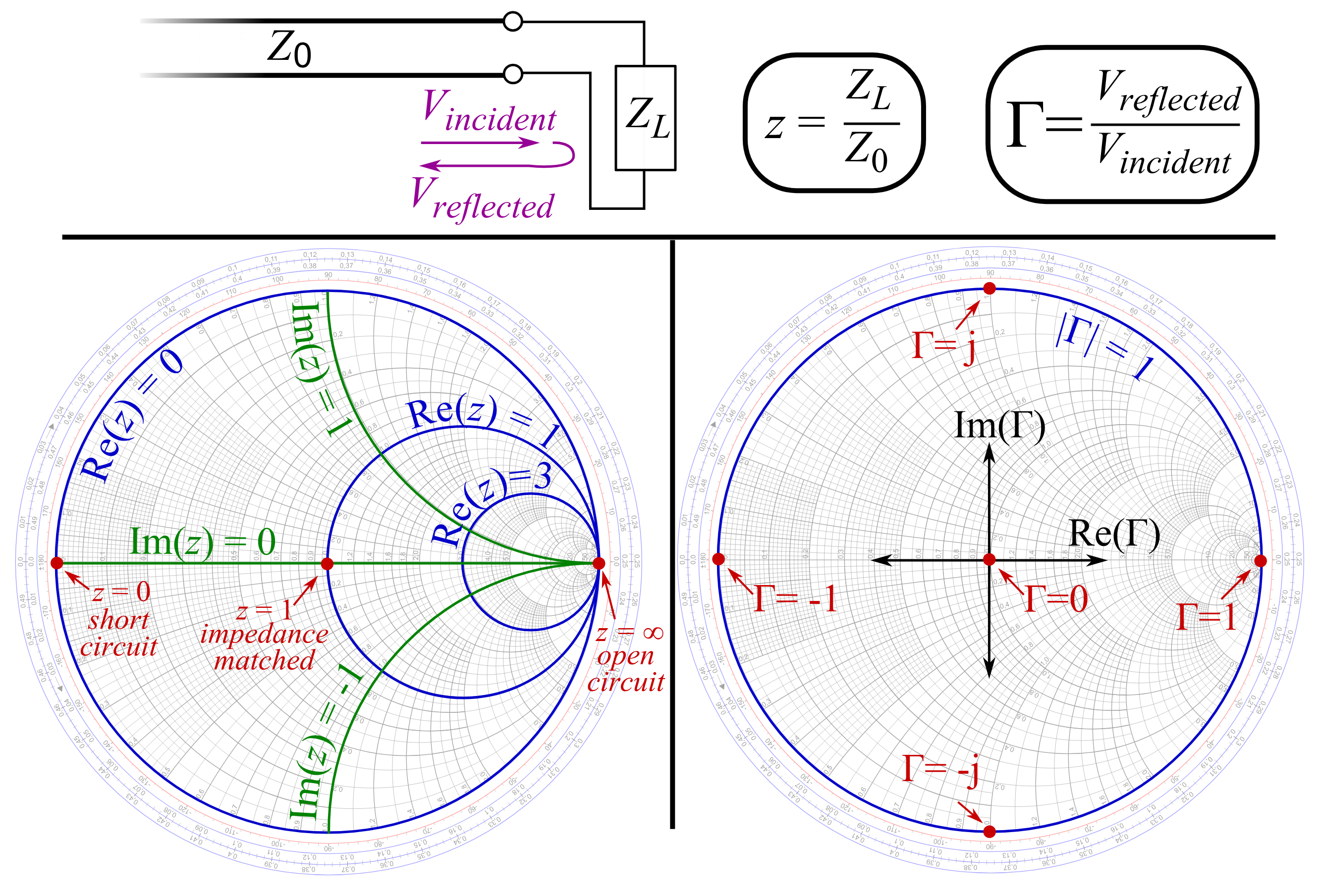
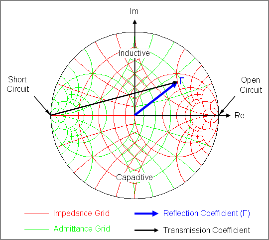
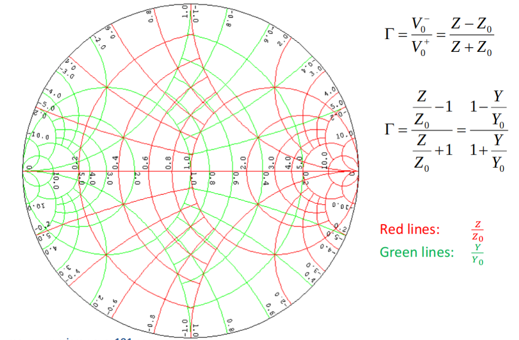
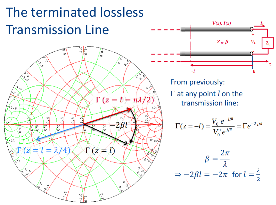
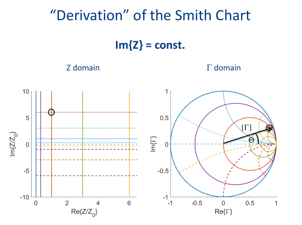
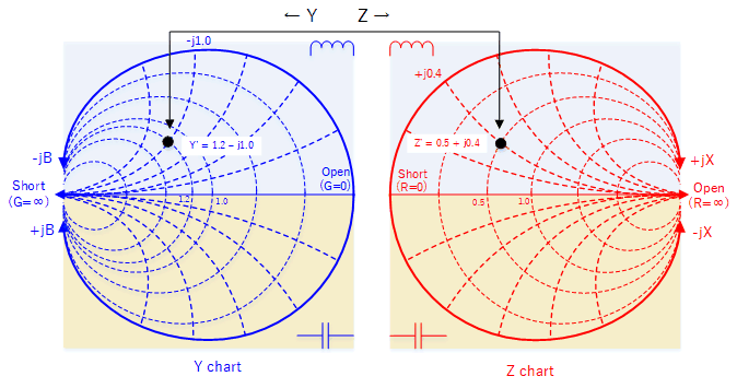
In the center it is the Load
finding reflection coefficient on smith chart
moving towards generator on smith chart
Passive microwave networks
5XTC0_Lecture_Module2_Passives.pdf
Formulas
Telegrapher’s Equations (frequency domain)
Voltage and Current in Transmission Line
Reflection Coefficient
Voltage and Current using
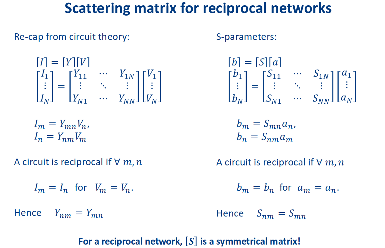
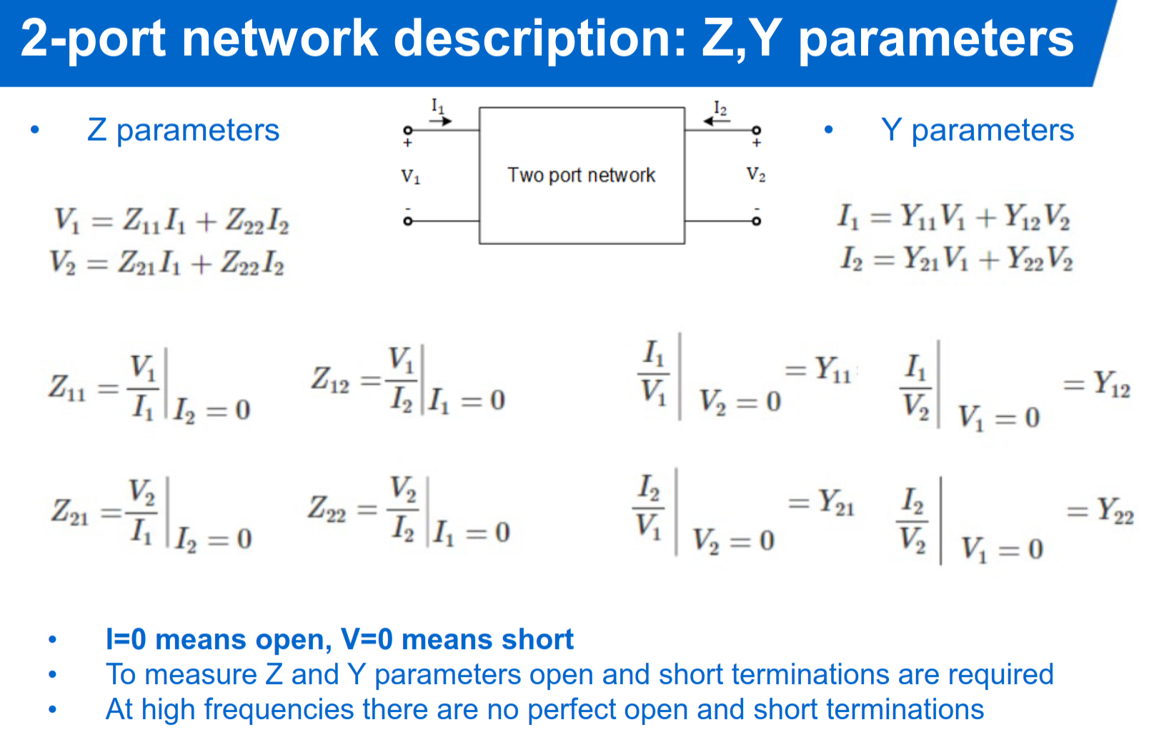
Impedance Matrix
Admittance Matrix
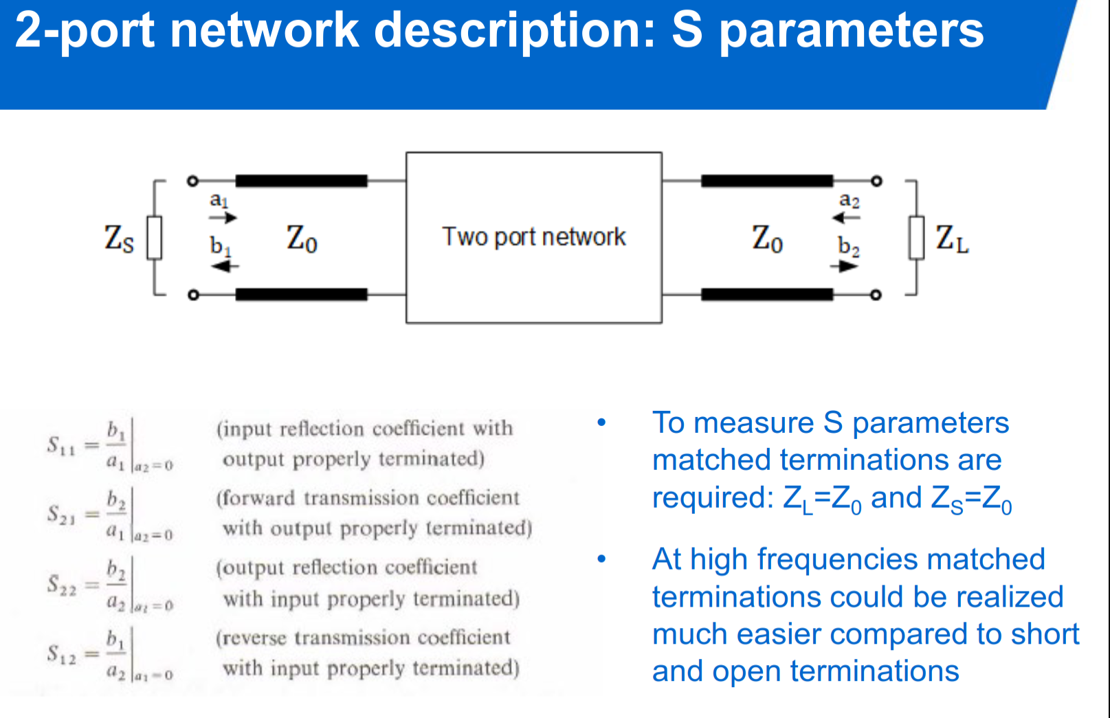
Scattering Parameters
Power at a Port
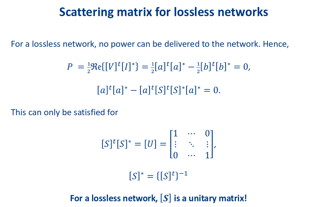
Unitary Condition (Lossless S-matrix)
Reciprocal Network (S-matrix Symmetry)
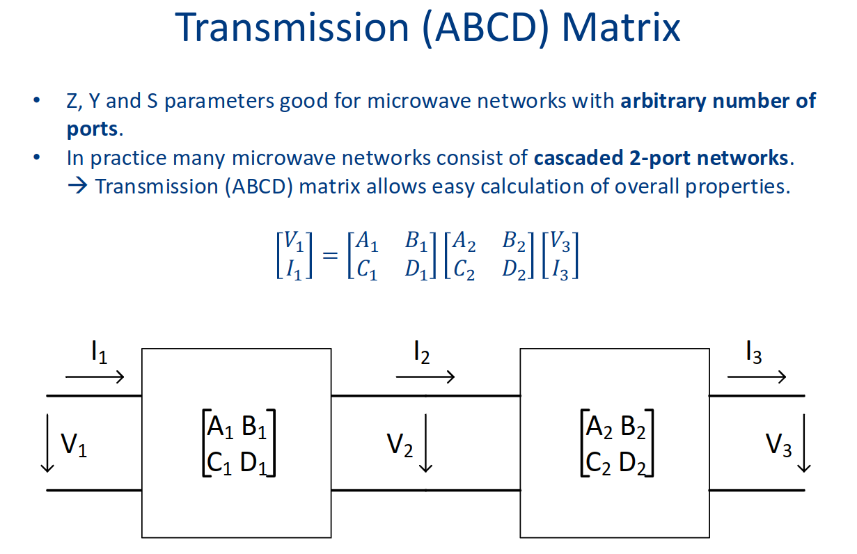
ABCD (Transmission) Matrix
Impedances of Lumped Elements (Series)
Admittances of Lumped Elements (Parallel)
Quarter-Wavelength Transformer
Transmission Line Impedance Transformation
Power Divider (Asymmetrical)
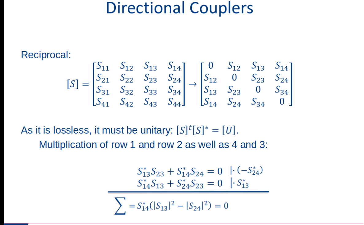
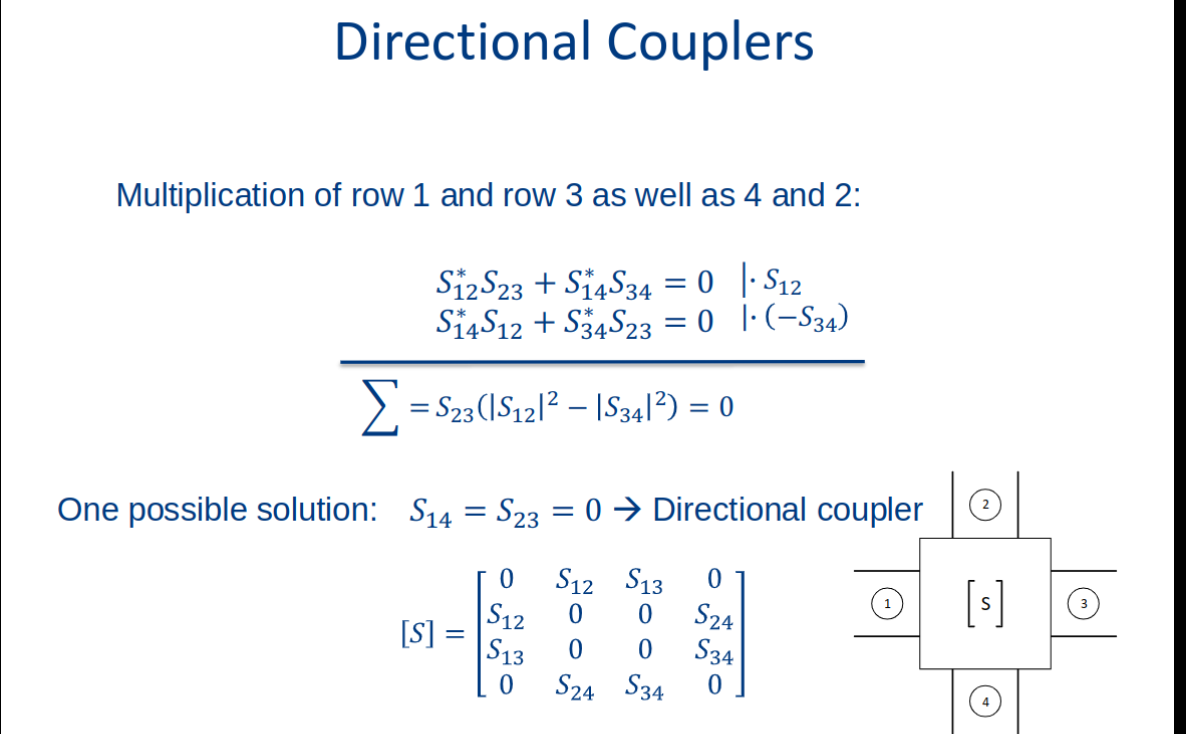
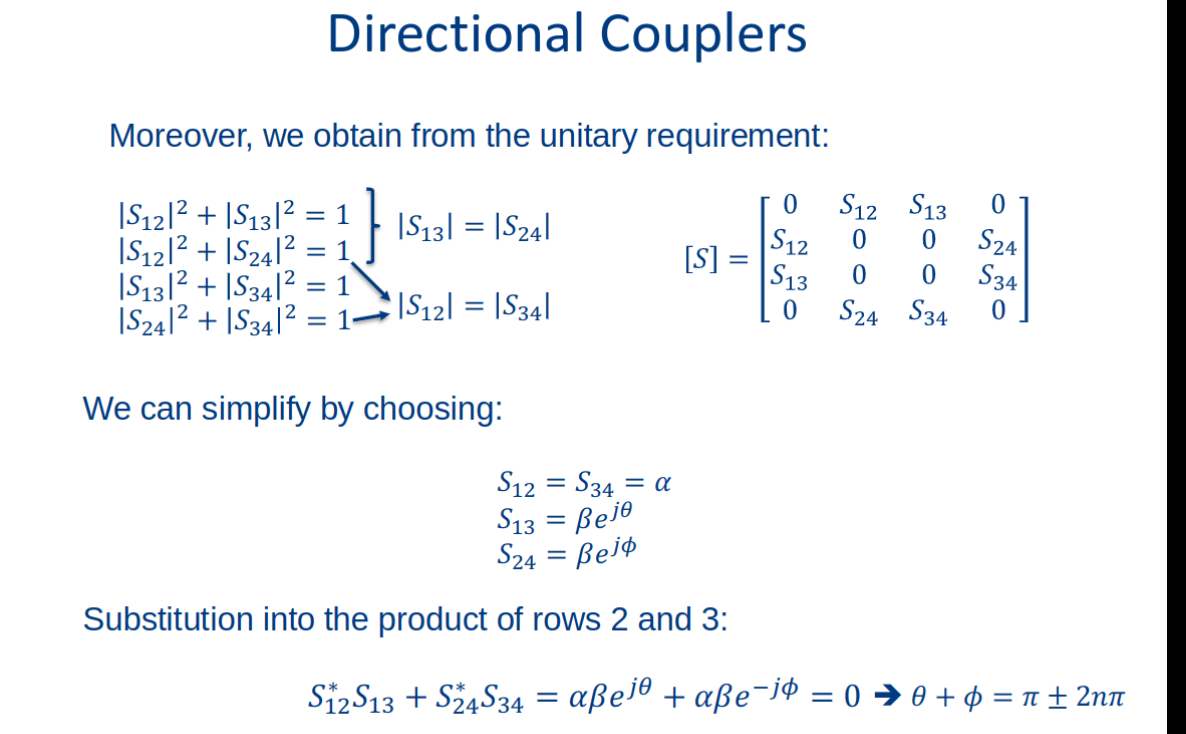
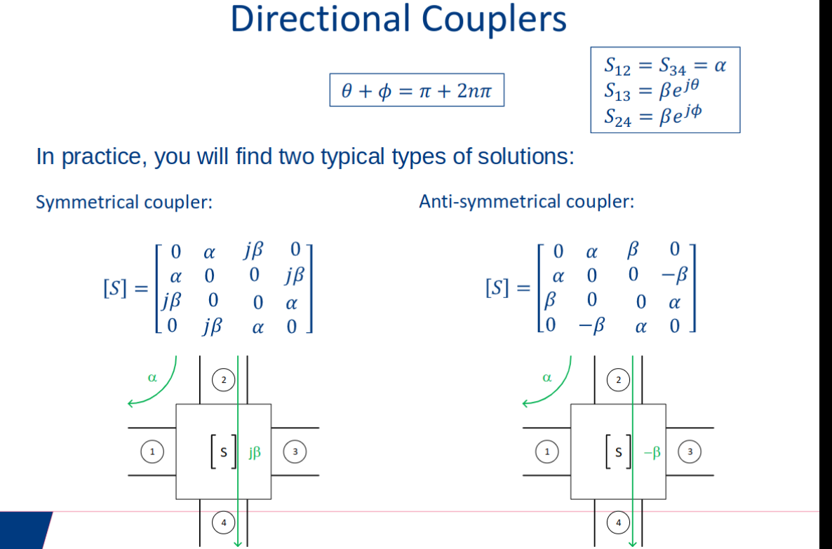
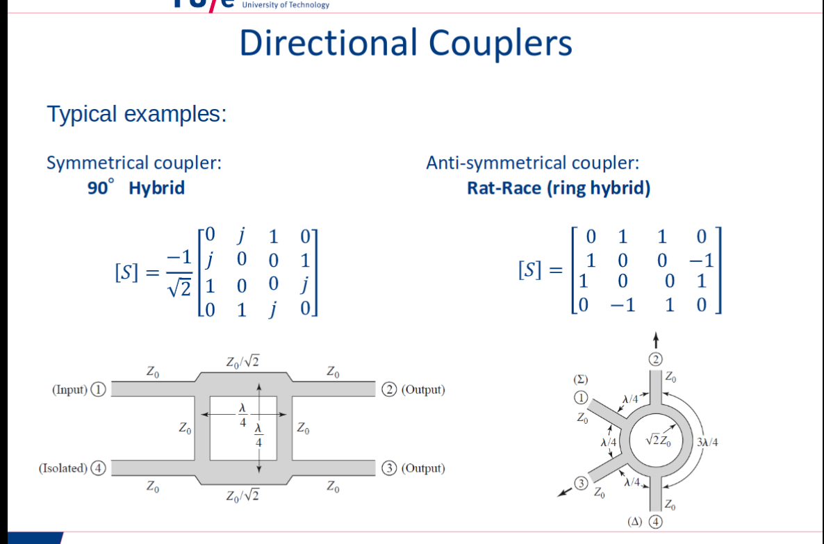
Directional Coupler (Symmetrical)
Directional Coupler (Anti-symmetrical)
Microwave network matrices
Topic: S-Parameters and Impedance Matching
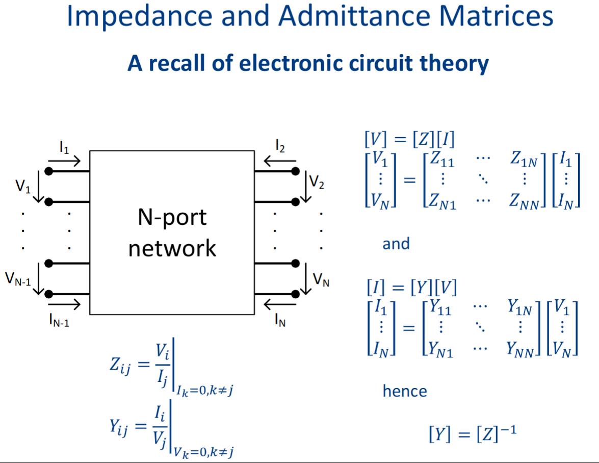
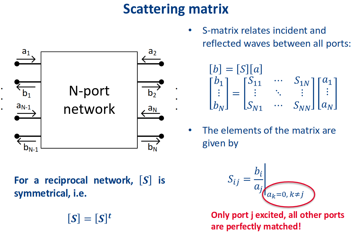
microwave circuits:
- Voltage and current difficult to measure (either separate measurement of
and or of standing wave pattern required) - Voltage and current difficult to define for non-TEM transmission lines.
Scattering parameters
using power relations: wave amplitudes defined to obtain meaningful power relations:
power delivered to port = incident - reflected wave
Impedance matching and tuning
Topic: S-Parameters and Impedance Matching
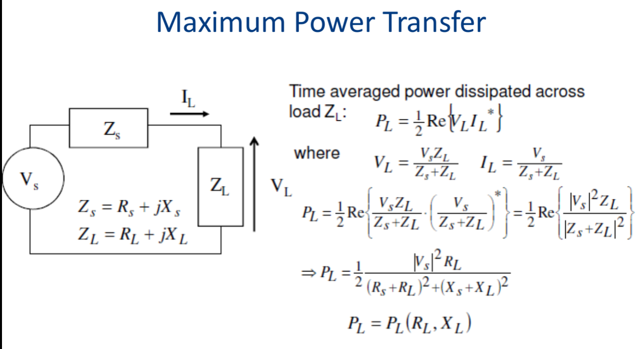
letting
Matching Network
normalizing impedance for smith chart:
de-normalizing (real impedance):
normalized impedance:
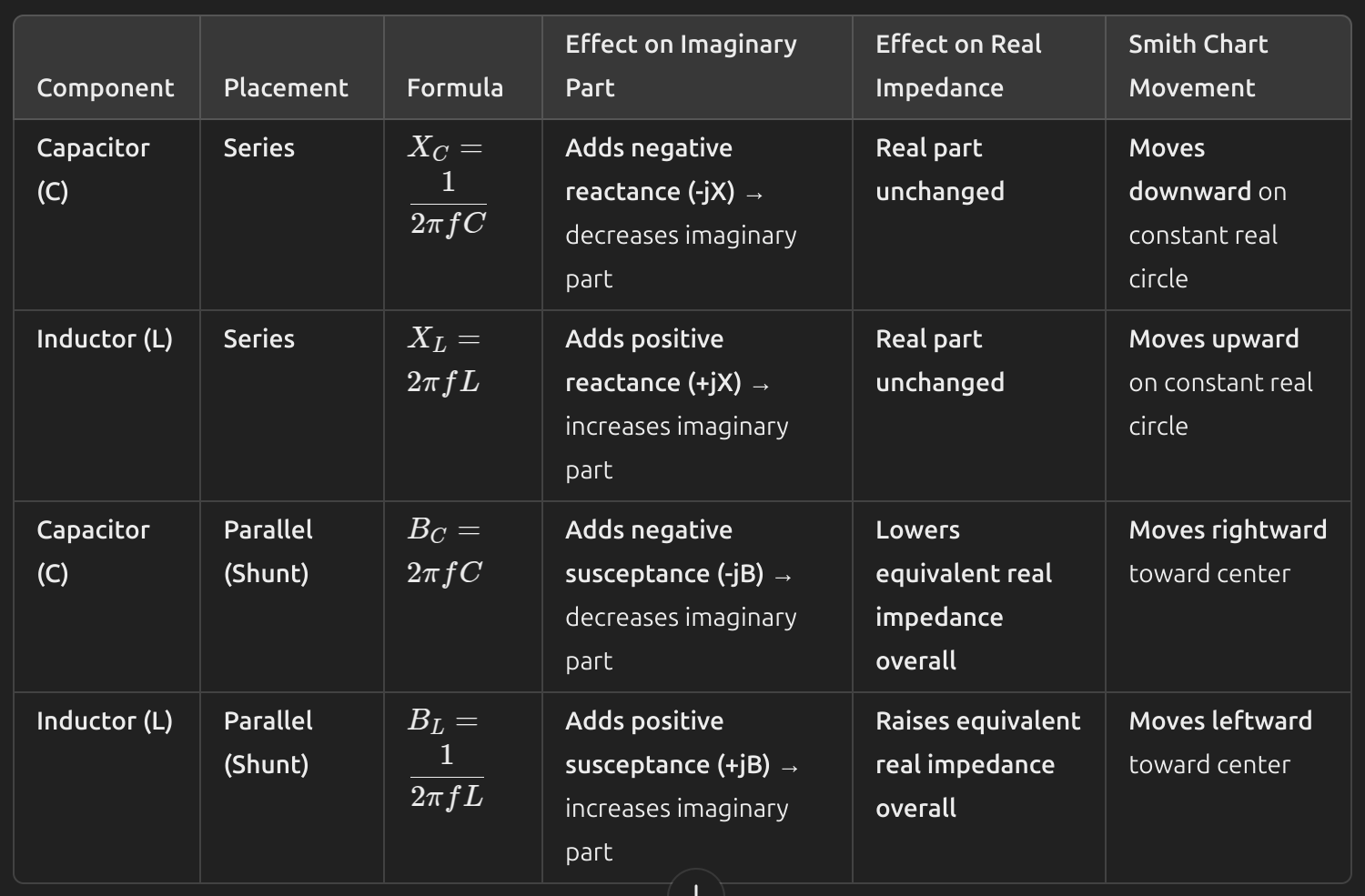
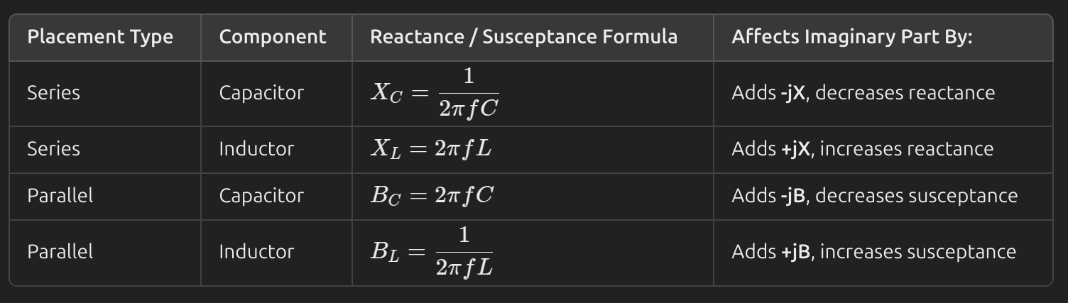
Impedance matching network
such network is pushed between source and load in the case there are reflections due to
, in the course we only deal with single frequencies but in general the impedance matching network can range for Broadband.
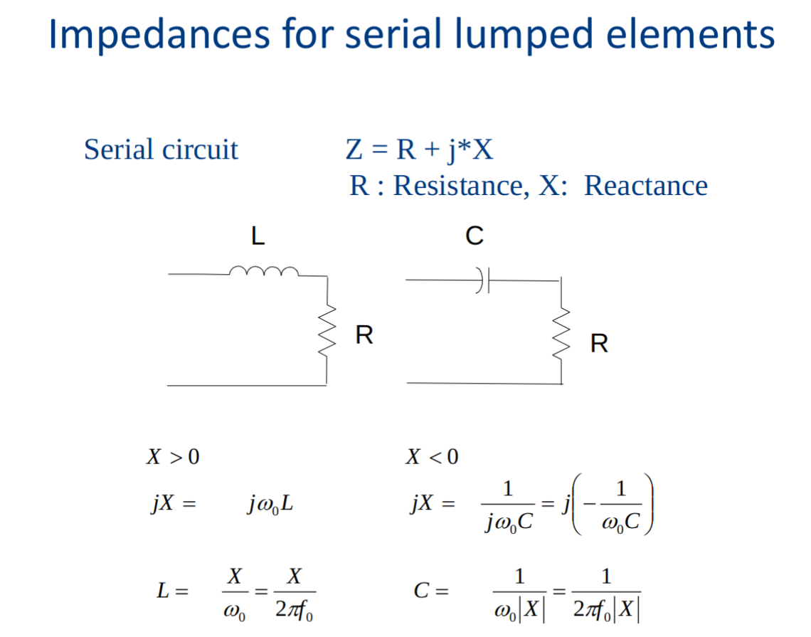
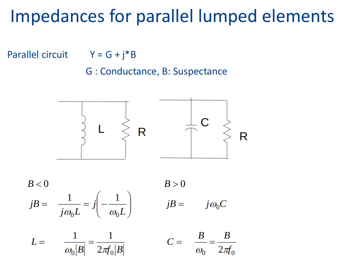
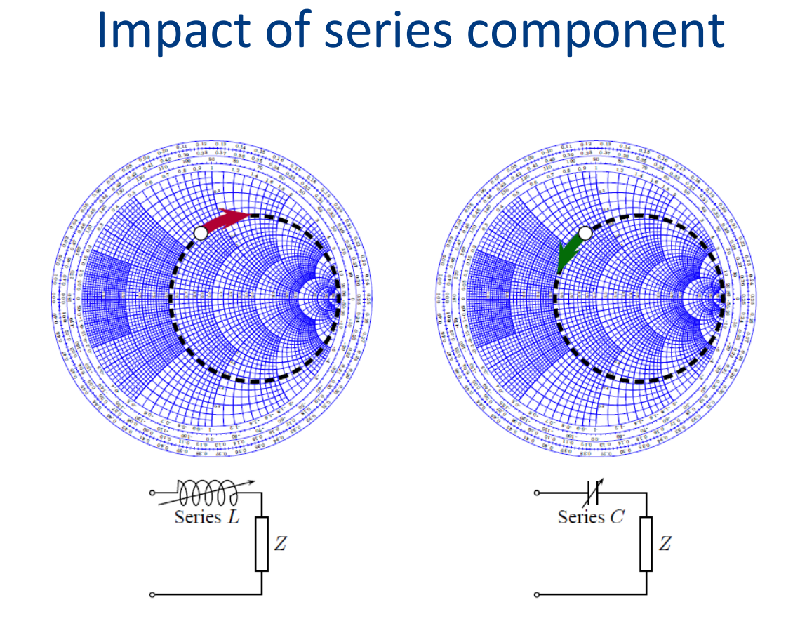
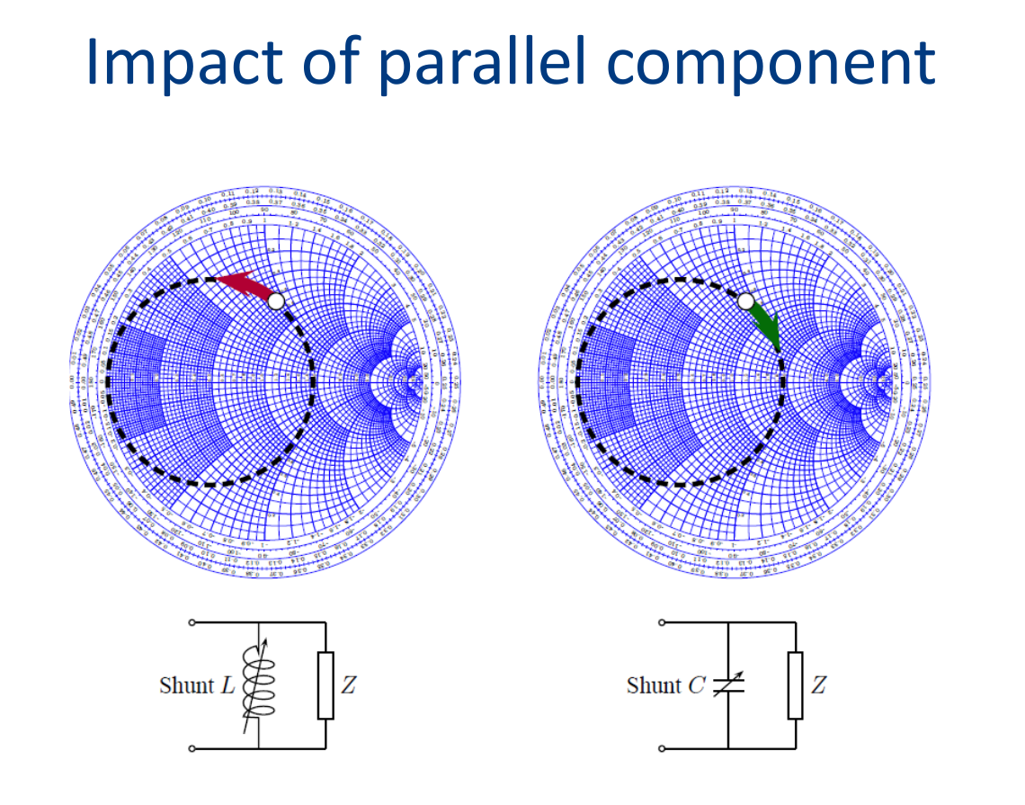
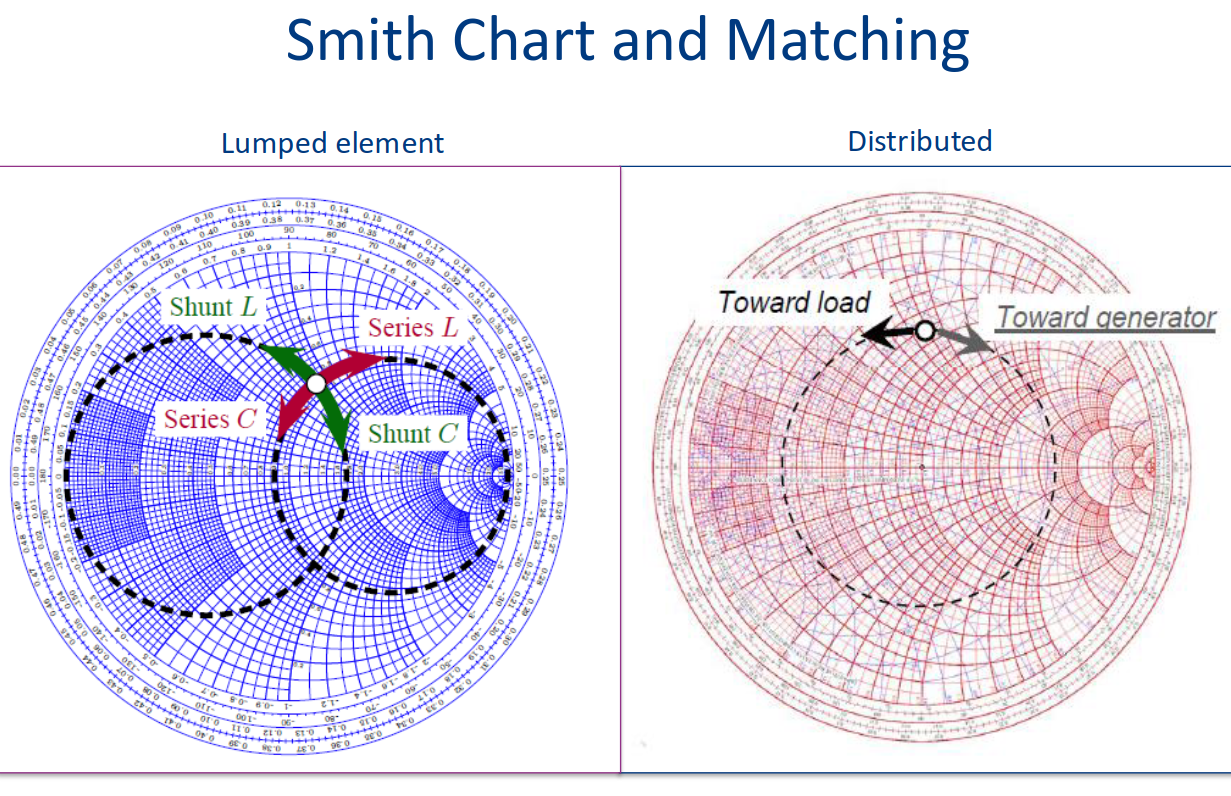
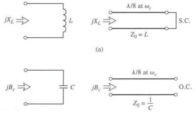
Distributed elements (using stubs to mimic lumped components)
inductances and capacitances can be achieved using
transmission lines:
Inductance:
Capacitance:
Power dividers and directional couplers
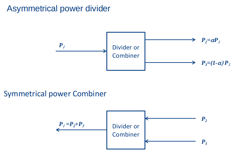
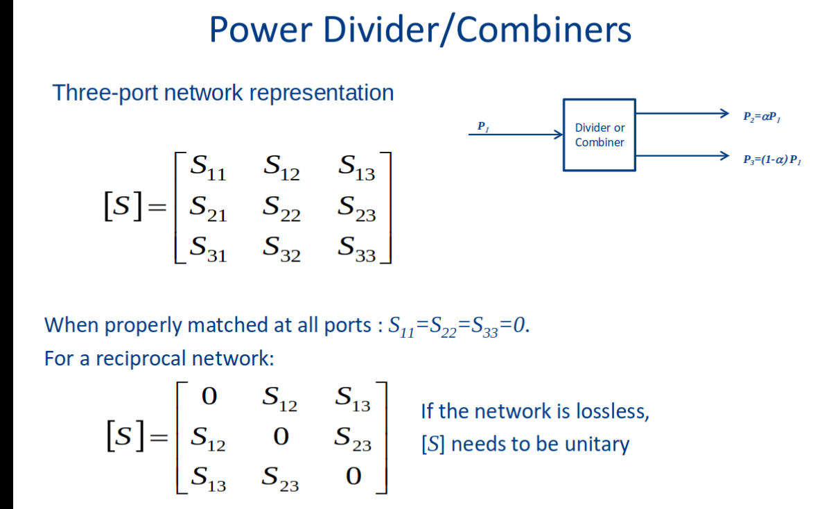
A power divider network can have symmetrical or asymmetrical.
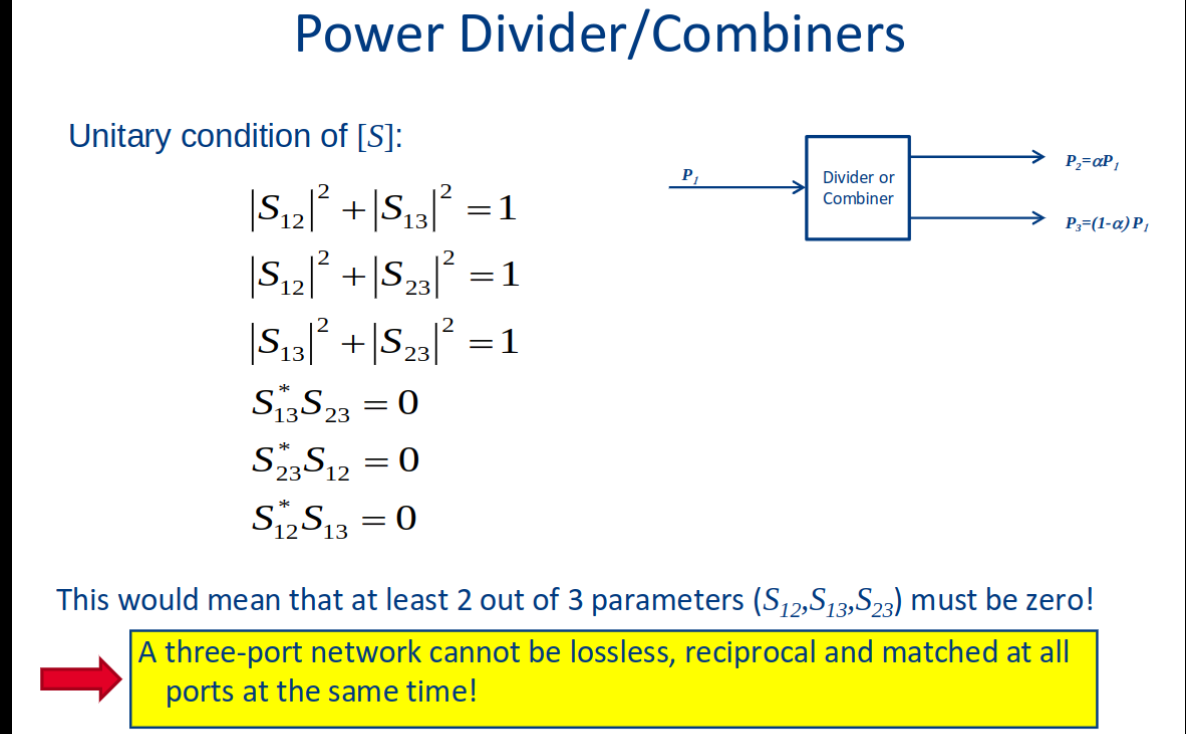
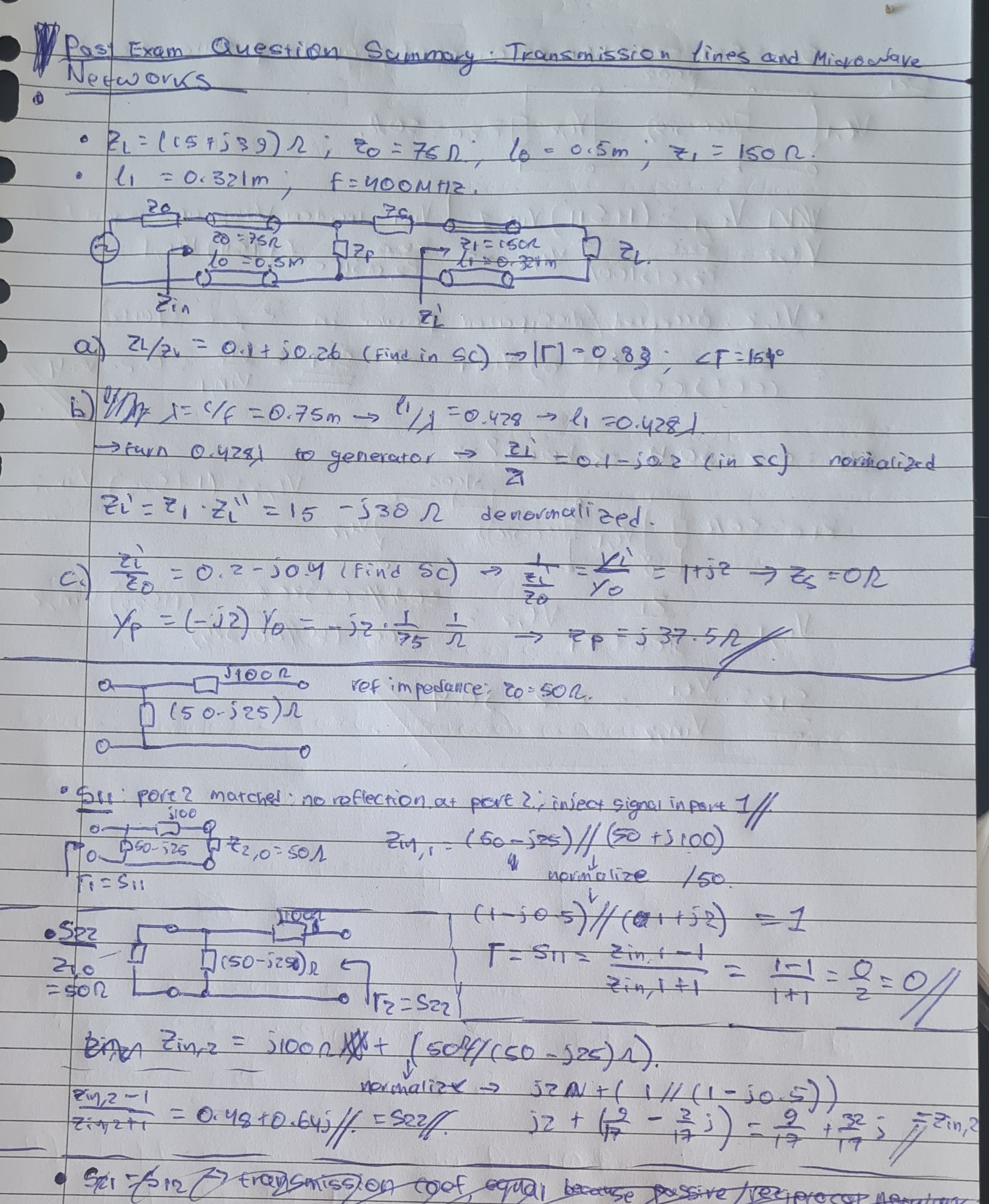
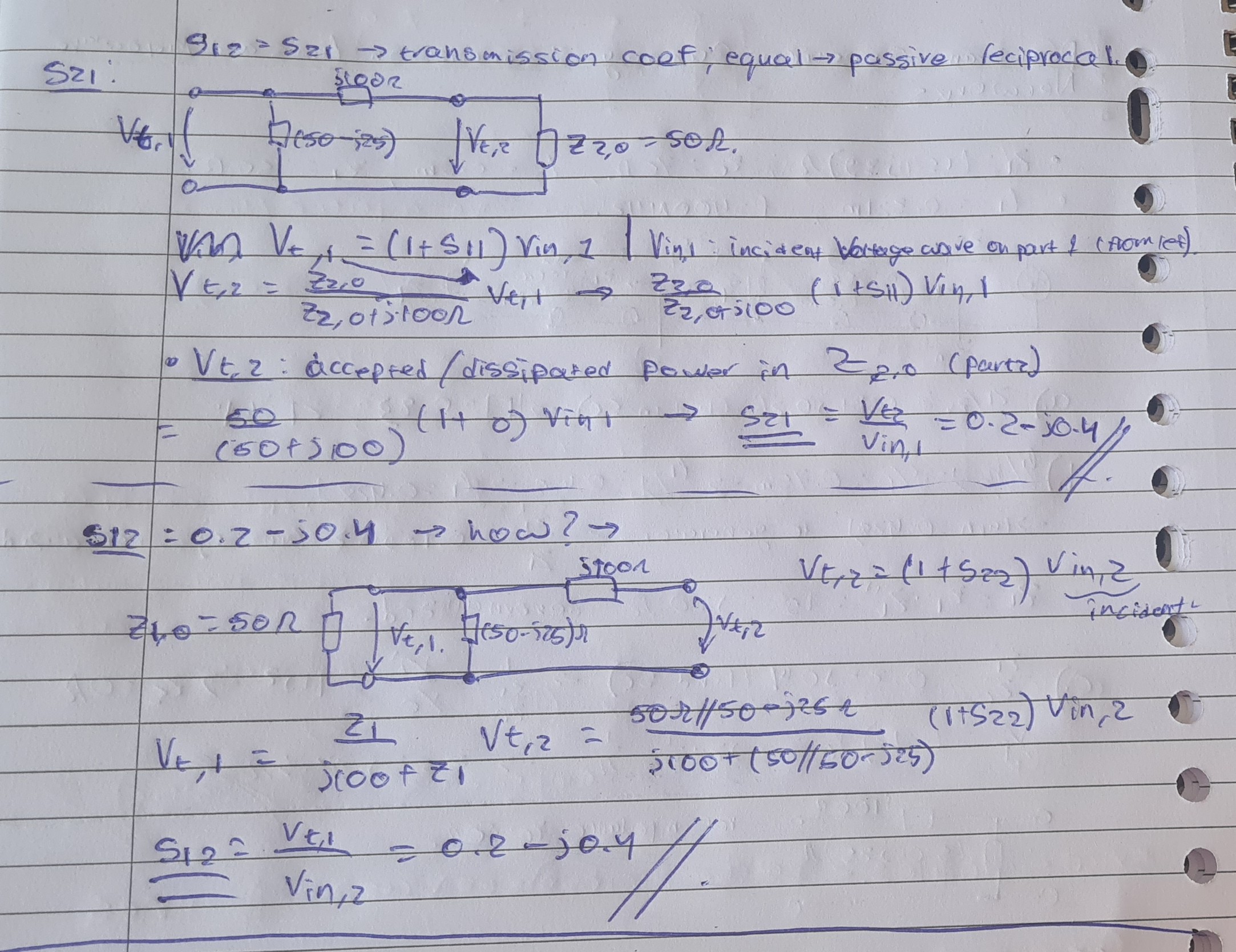
Matrix Based Question
Antenna parameters & theory
Topic: Antennas and Radiation
5XTC0_Lecture_Module3_Antenna-Parameters-3.pdf
Formulas
Poynting Vector (Instantaneous):
Time-Averaged Power Density:
Radiation Intensity:
Surface Element in Spherical Coordinates:
Solid Angle:
Total Radiated Power:
Directivity:
Gain:
Gain vs Directivity:
Reflection Efficiency:
Axial Ratio (AR):
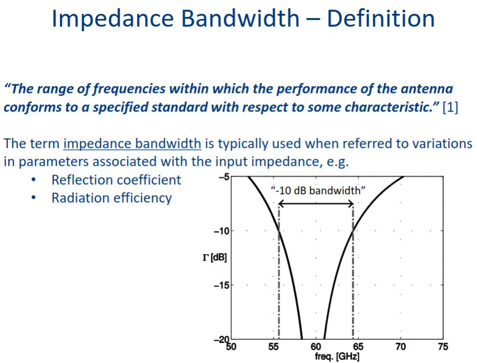
Bandwidth:
Narrowband Percentage:
Input Impedance (Thevenin Model):
Input Admittance (Norton Model):
Radiation Efficiency (Power-Based):
Received Power and Effective Aperture:
Effective Aperture:
Max Effective Aperture (Matched Case):
Free Space Power Density:
Max Effective Aperture (Dipole Example):
Friis Transmission Equation:
Gain-to-Aperture Relationship:
Radiation parameters
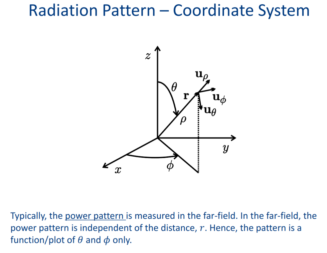
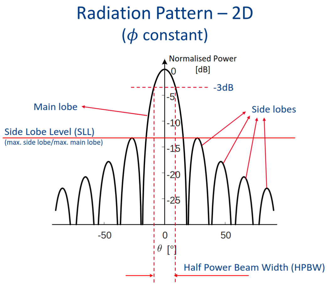
Radiation Pattern
spatial distribution of quantity that characterizes the electromagnetic field generated by an antenna.
The distribution can be expressed as mathematical function as graphical representation.
when the amplitude or relative amplitude of a specified component of the electric-field vector is plotted graphically, it is called an amplitude pattern, field pattern or voltage pattern. When the square of the amplitude or relative amplitude is plotted, it is called a power pattern.
-
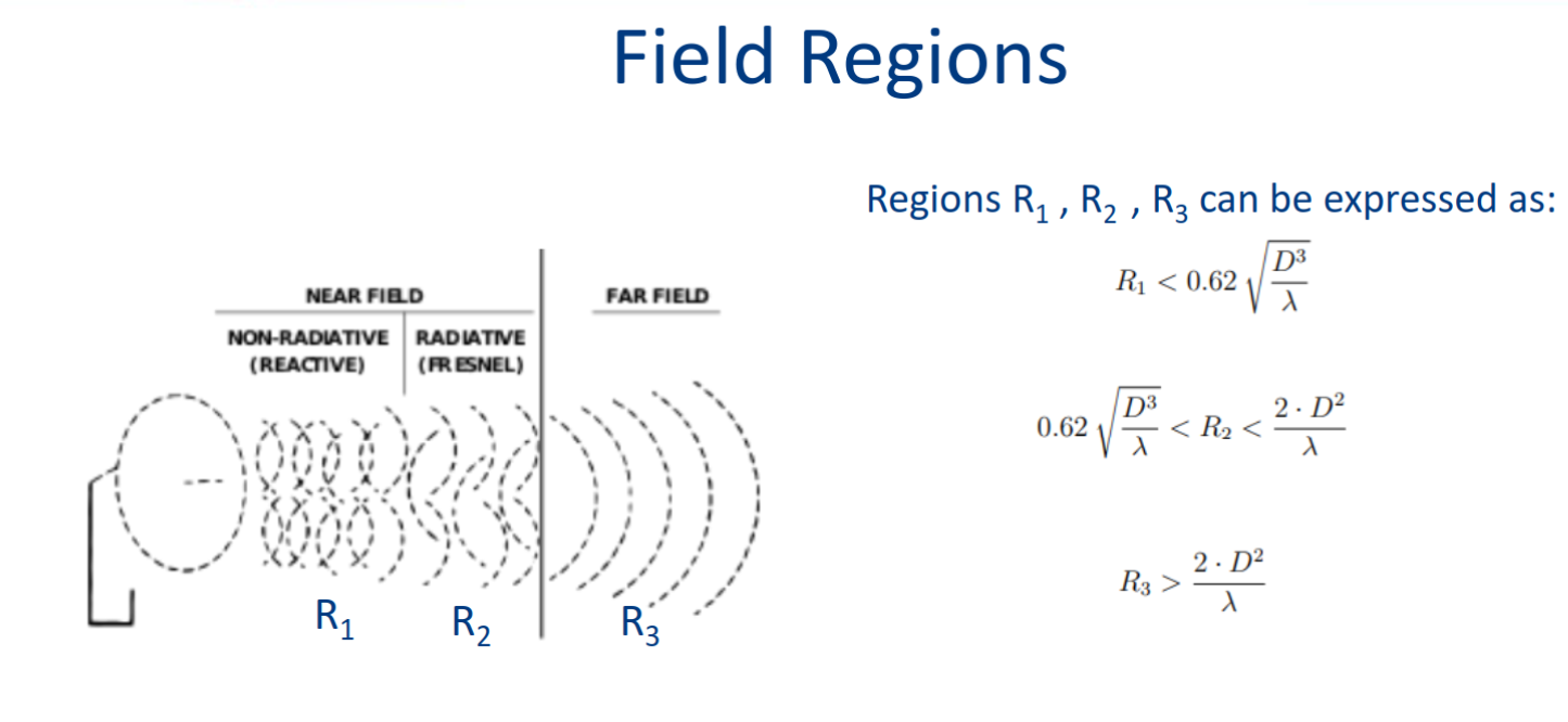
Reactive near-field region:
-
Reactive fields predominate
-
Radiation pattern changes with
-
Radiating near-field (Fresnel) region:
-
Radiation fields predominate
-
Radiation pattern changes with
-
Far-field (Frauhofer) region:
-
-
Radiation fields predominate
-
Radiation pattern independent of
Near and far field - Wikipedia
Poynnting vector:
The power density decays with
To have power independent figure we normalize the radiation intensity with respective radiation intensity of (ideal) isotropic radiator:
To know the directivity radiated power is needed, we obtain gain:
Directivity - Wikipedia
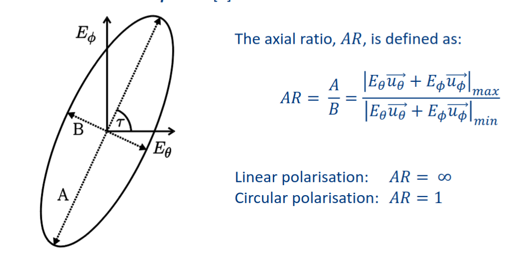
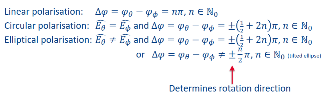
Polarization
In a specified direction from an antenna and at a point in its far field, the polarization of the (locally) plane wave that is used to represent the radiated wave at that point.
wave propagating towards
, and its electric field can be decomposed in time domain:
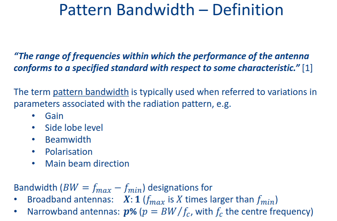
Circuit level representation
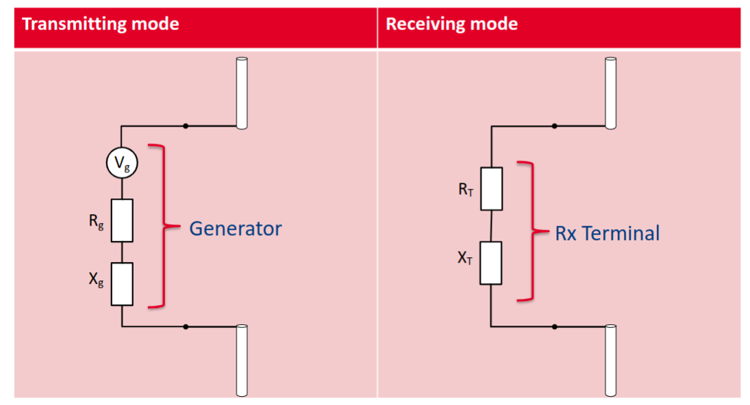
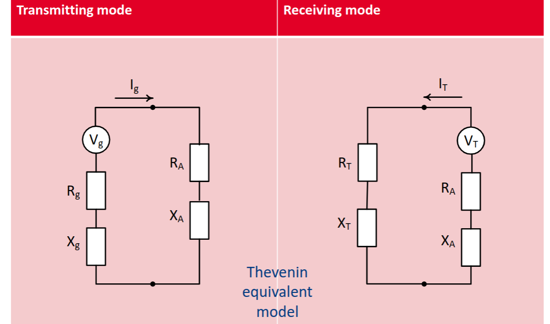
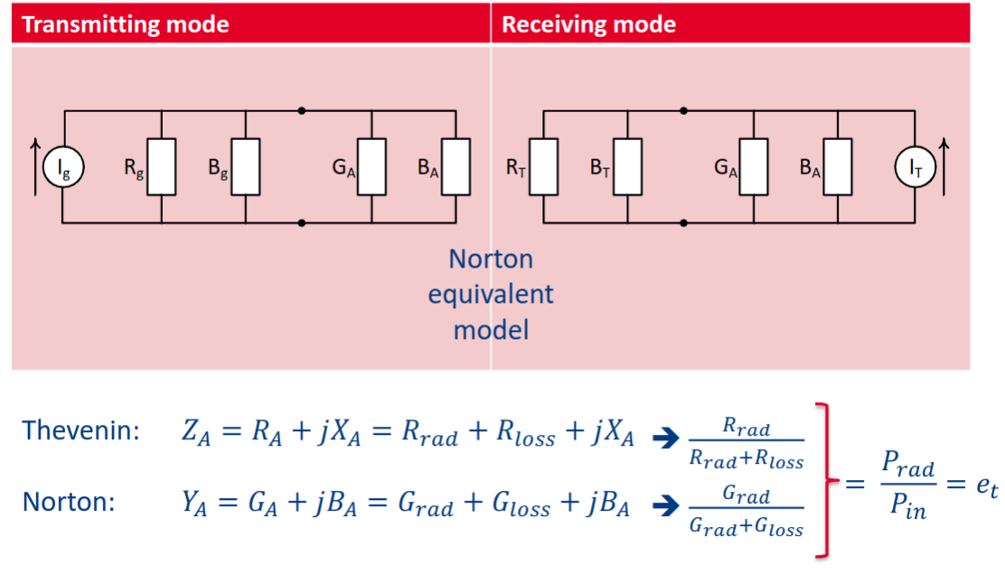
In receive mode the power
Propagation channel basics
Topic: Wireless Channel
The Friis transmission equation relates the power received by an antenna 2 to the radiated power by antenna 1 and vice versa.
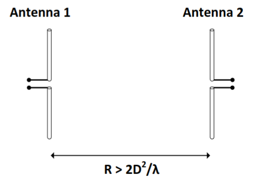
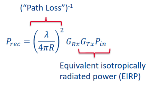
The power density of isotropic radiator at distance
power received by antenna 2 depends on its effective aperture:
Ratio of gain to effective aperture in certain direction is same for all antennas, for example for very short dipole
Friis Transmission equation:
Friis transmission equation - Wikipedia
FSPL - Free Space Path Loss: influenced by frequency operation - Friis equation → has a wavelength component.
RF systems and Amplifier design
5XTC0_Module_4_Amplifier_Design.pdf
Formulas
Reflection Coefficients
Input and Output Reflection Coefficients
Power Calculations
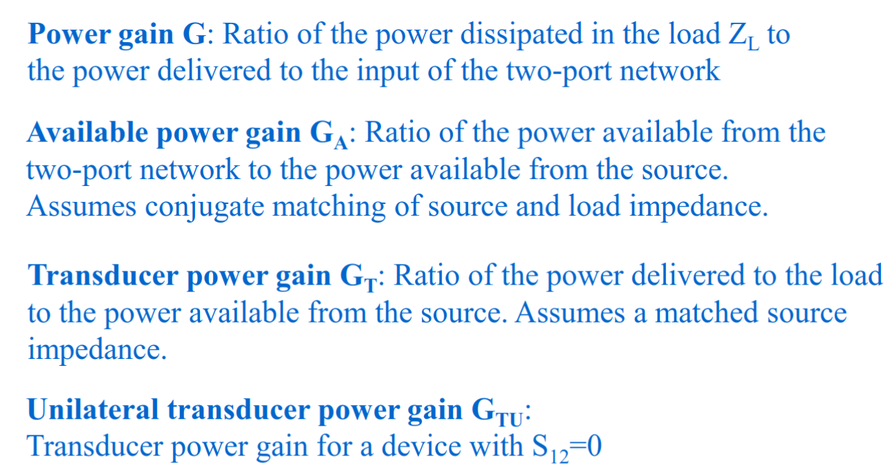
Power Gains
Power gain:
Available power gain:
Transducer gain:
Unilateral transducer gain (S₁₂ = 0):
Gain Circle Parameters
Normalized gain factor:
Center:
Radius:Stability Factor and Condition
Rollet stability factor:
Condition for unconditional stability:
and Stability Circle Centers and Radii
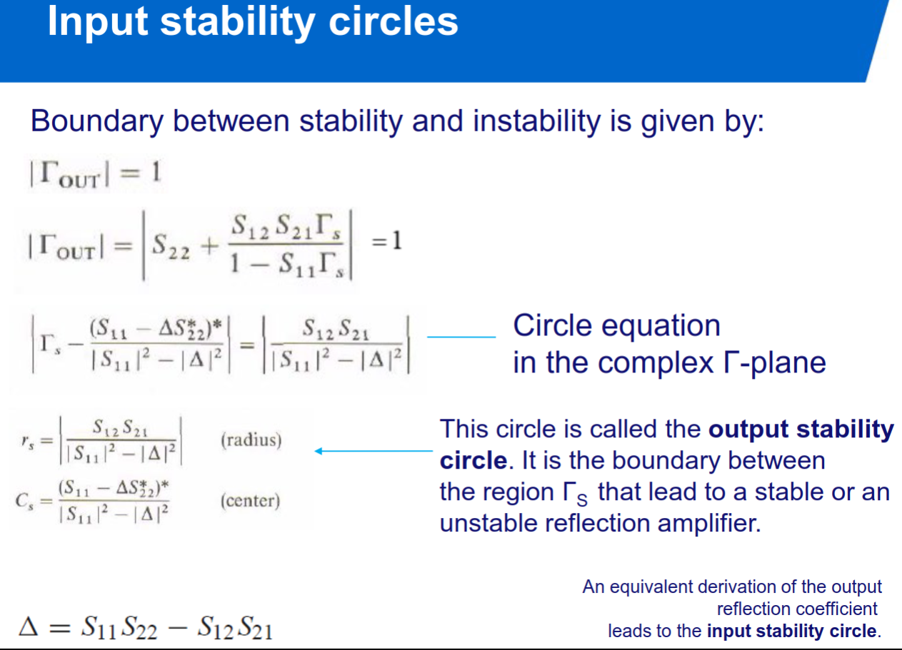
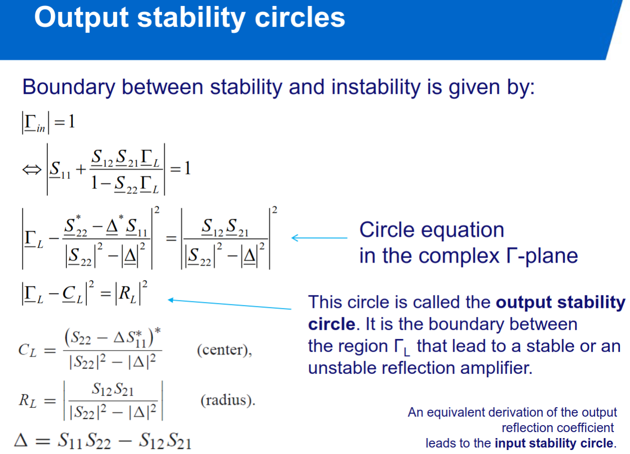
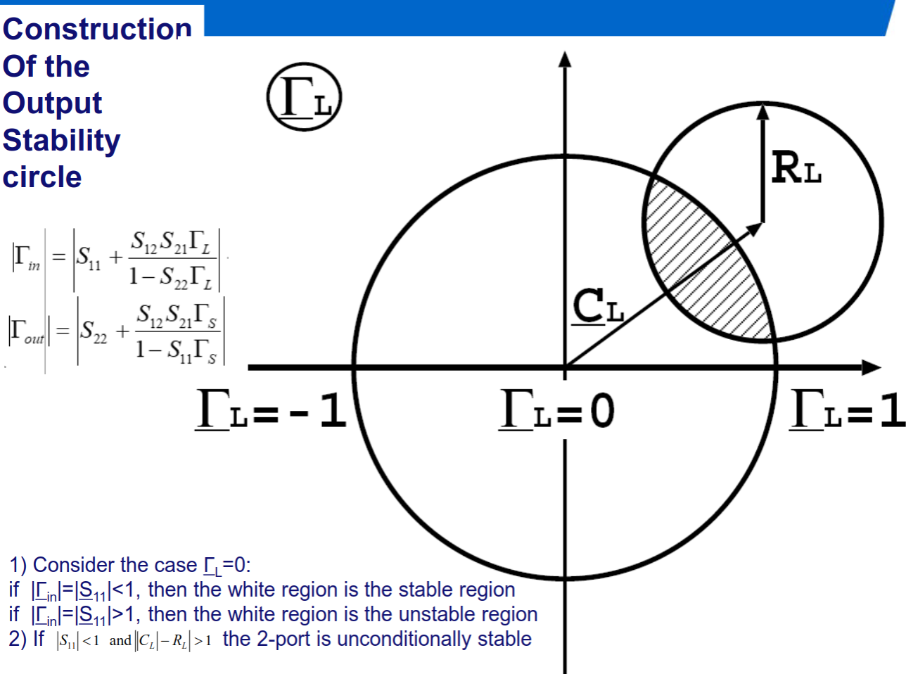
Input stability circle (in Γ_L plane):
Output stability circle (in Γ_S plane):
RF systems
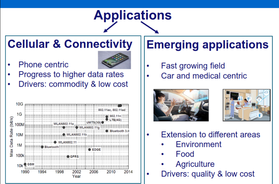
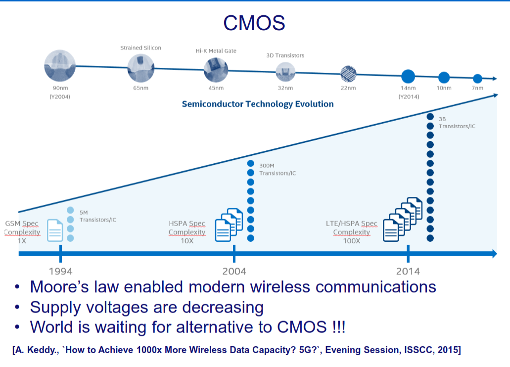
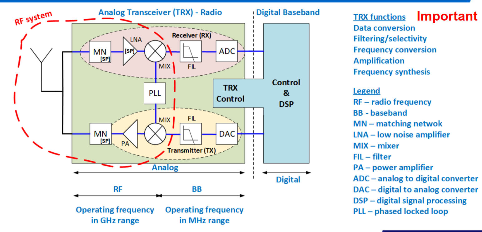
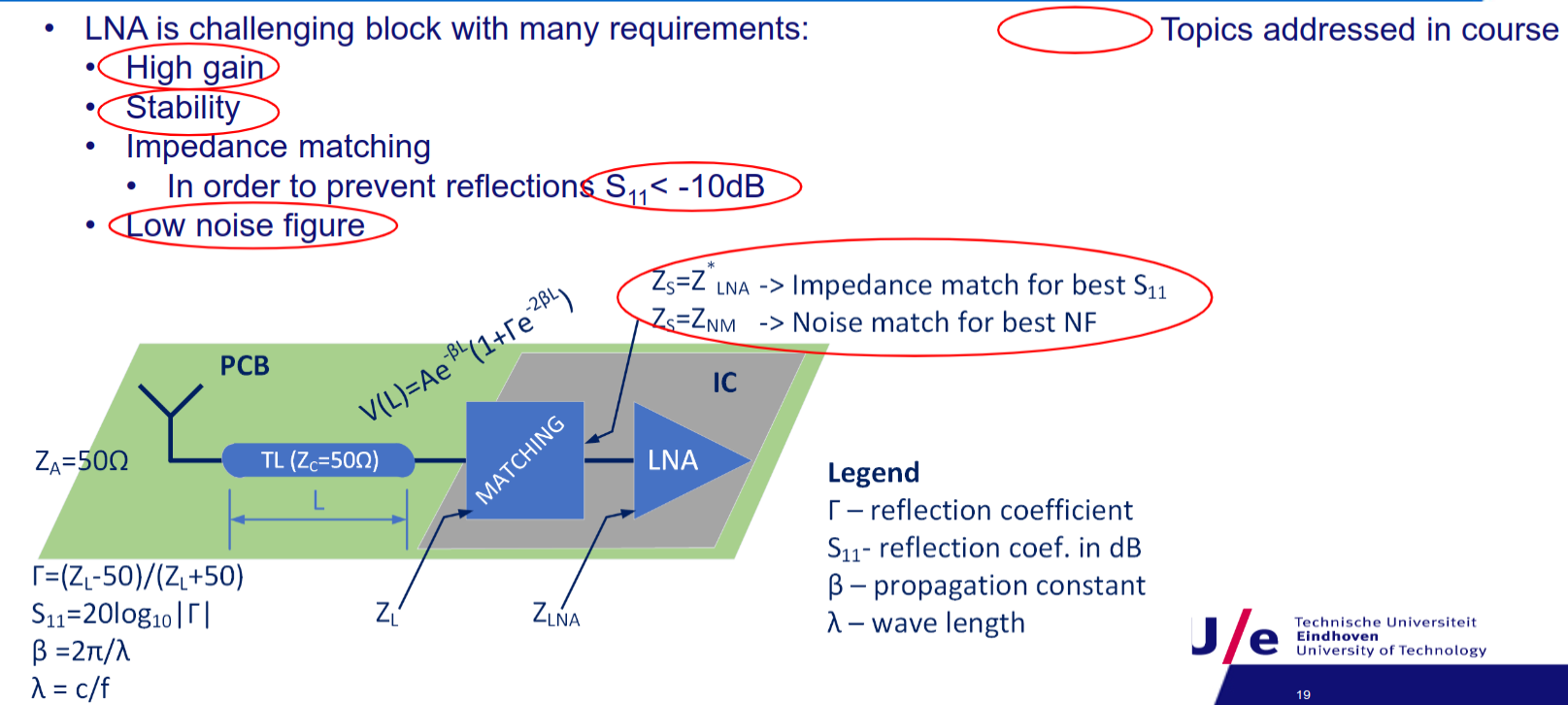
Amplifier design
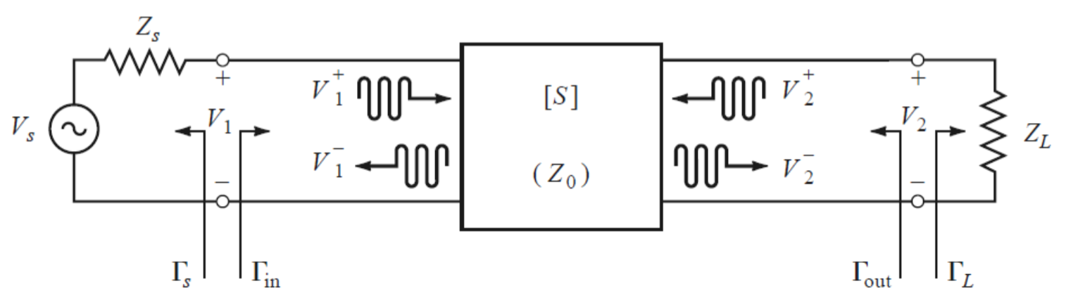
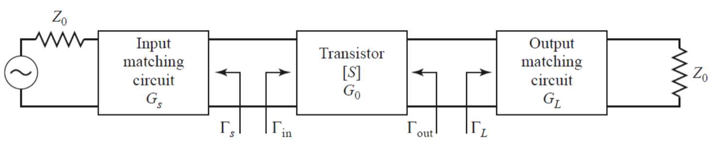
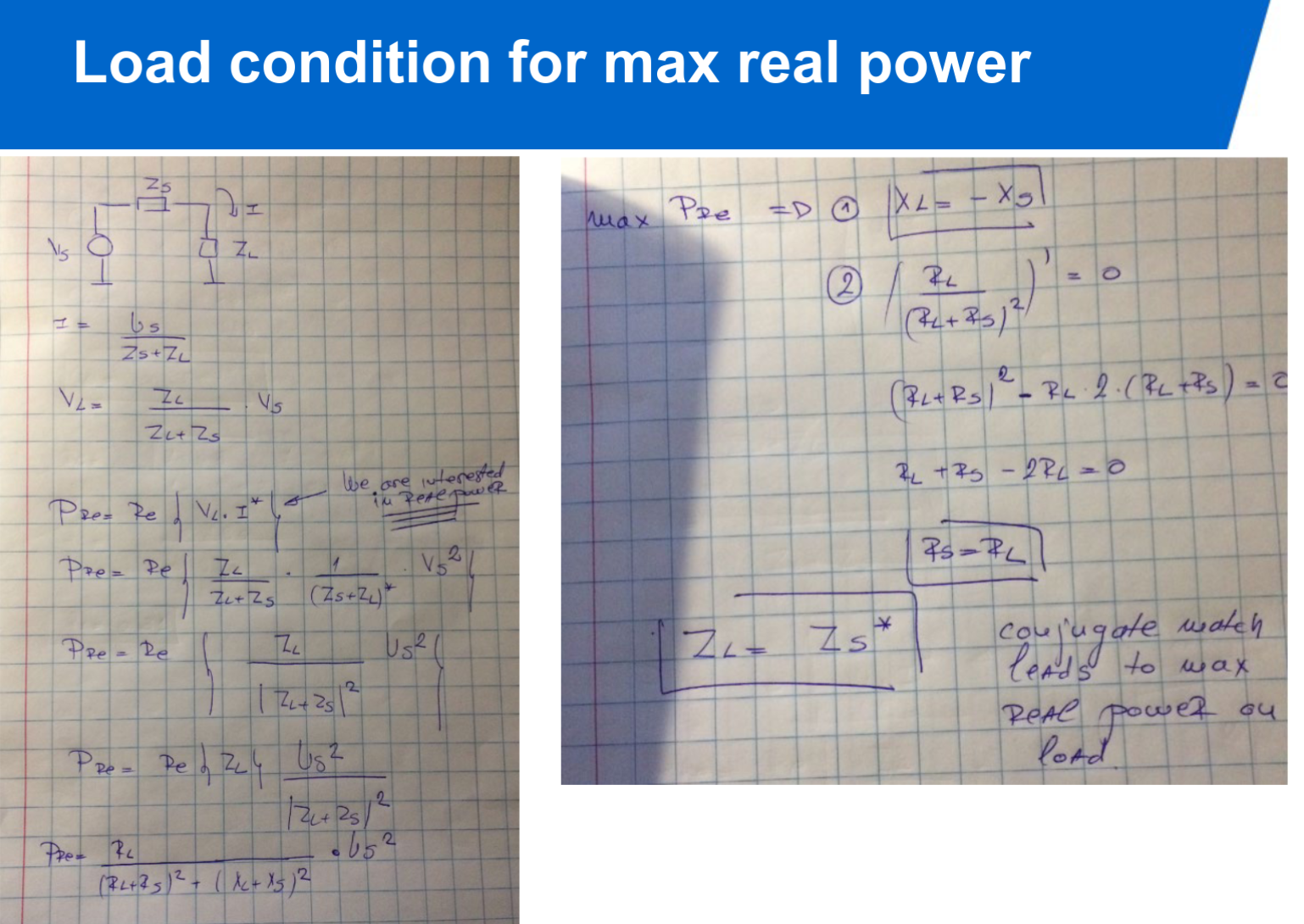
- Power available from source:
, when source impedance is conjugately matched to input impedance: . - Power available from network:
, when load impedance is conjugately matched to output impedance: .
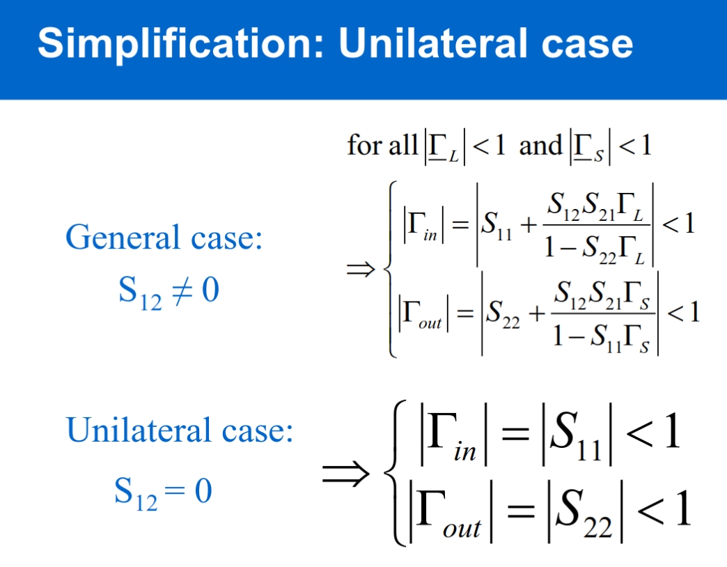
Unilateral Amplifier
An amplifier whose output exhibits no feedback to its input side is described as ‘unilateral’. The input impedance of a unilateral amplifier is independent of load, and output impedance is independent of signal source impedance.
If
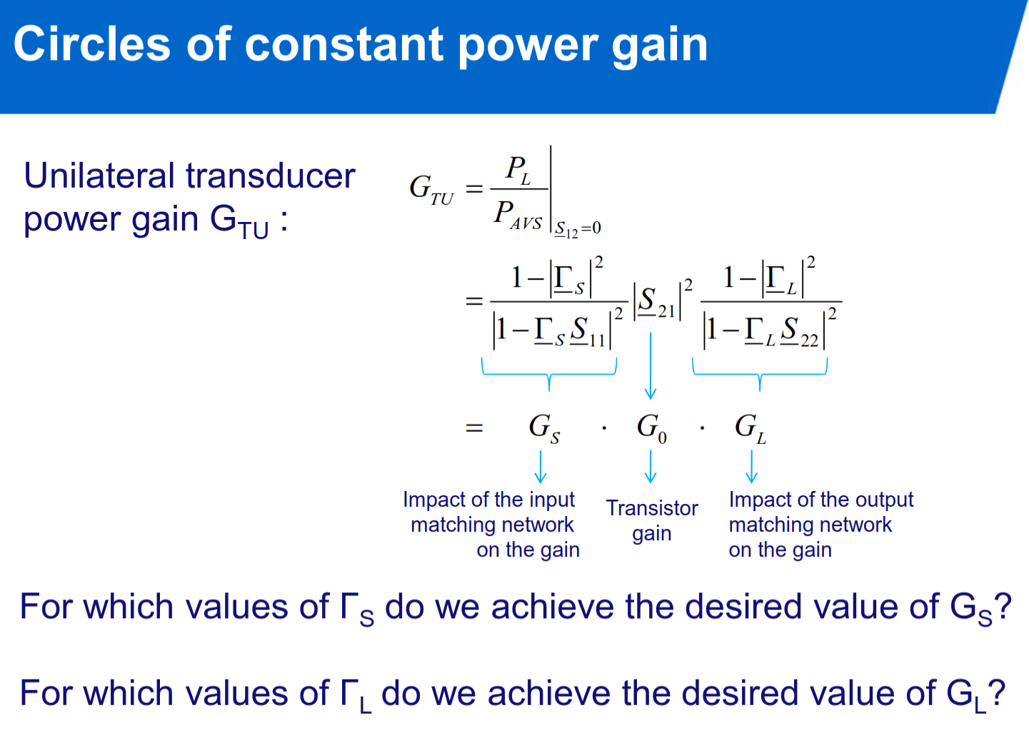
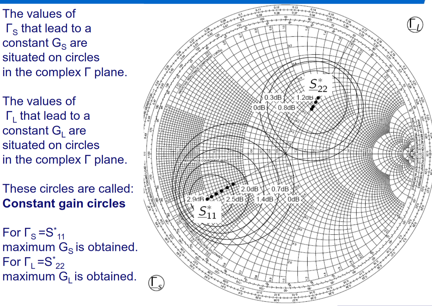
circles of constant power gain:
max gain of input and output matching networks:
normalized gain factors
center and radius of constant gain circle for input and output matching network:
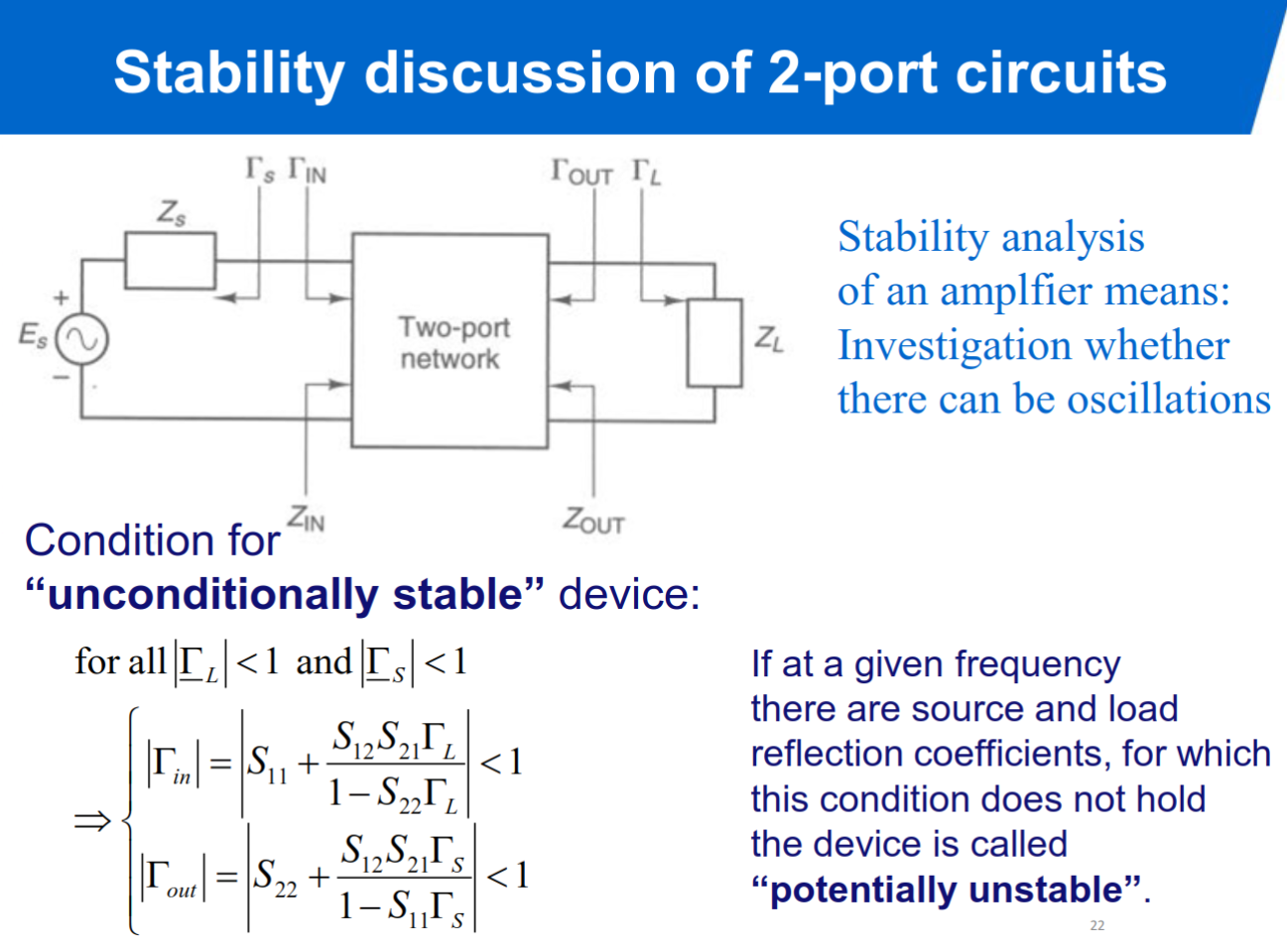
If
Where K is the Rollet stability factor.
Noise and LNA design
Topic: Noise
5XTC0_Module_5_Exercise_Amplifier_and_Low_Noise_Amplier_design.pdf
Formulas
Power Gain:
Available Power Gain:
Transducer Power Gain:
Unilateral Transducer Gain (S_{12}=0):
Reflection Coefficients:
, Rollet Stability Factor:
, with Unconditional Stability Conditions:
and Thermal Noise Power:
Available Noise Power from Resistor:
Equivalent Noise Temperature:
Noise Figure:
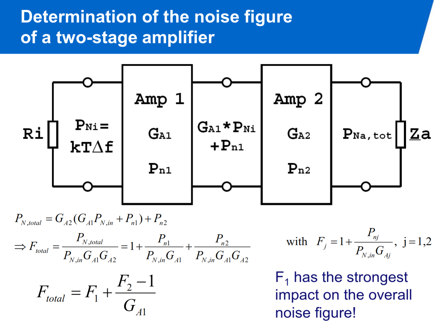
, with Friis’ Formula for Cascaded Stages:
Noise Figure with Source Admittance:
Noise Figure with Reflection Coefficients:
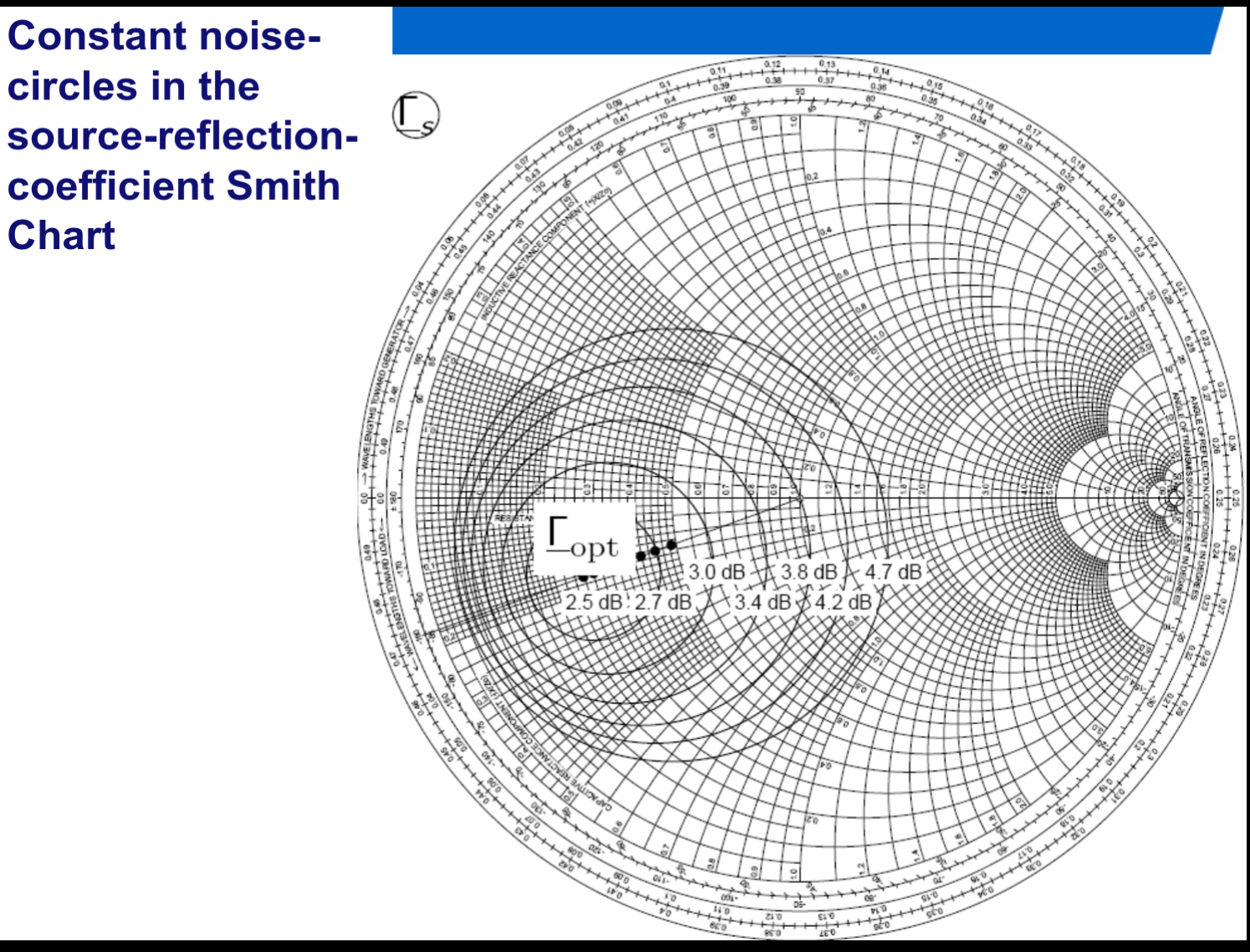
Constant Noise Circle Radius:
Constant Noise Circle Center:
Other
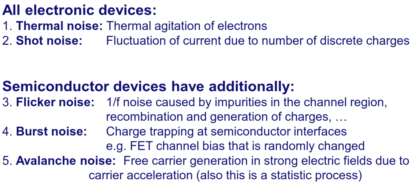
Thermal noise:
average voltage is zero, but non zero average power.
White noise:
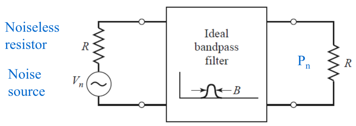
Noise of arbitrary source:
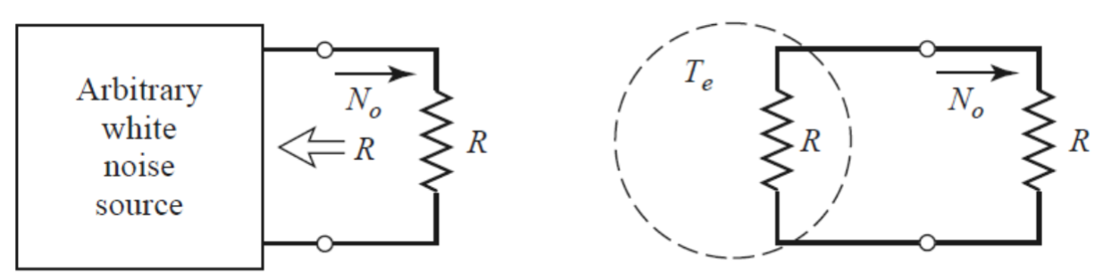
equivalent noise temperature:
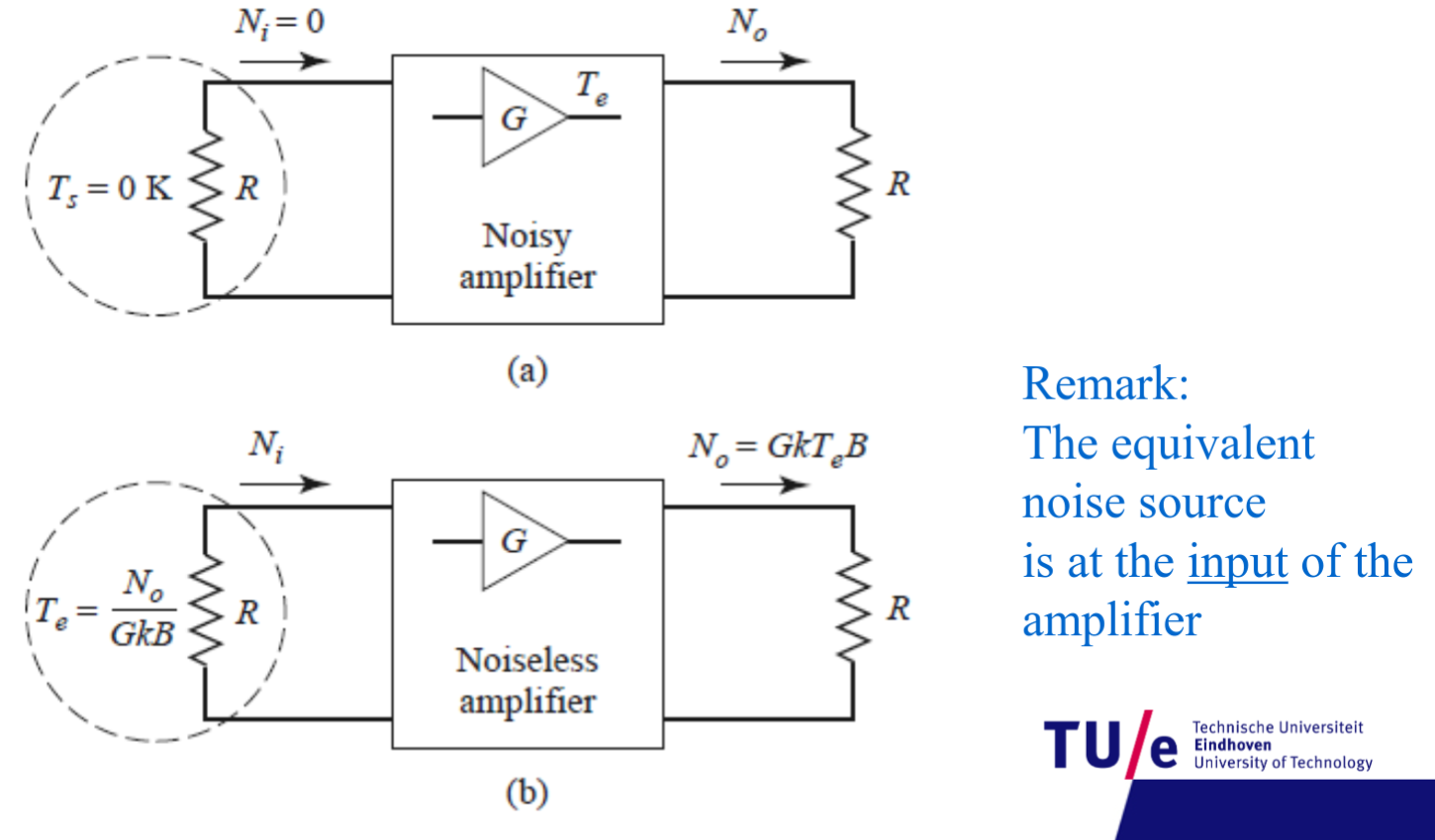
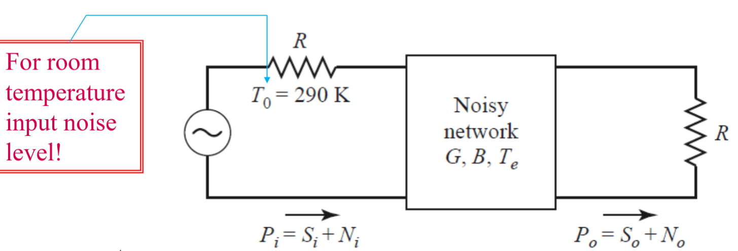
Gain, F and
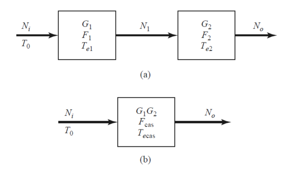
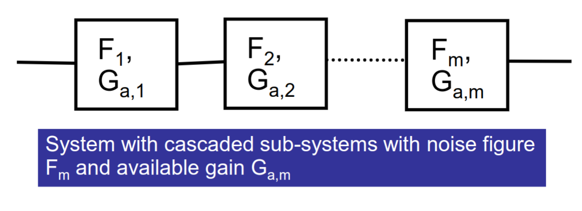
Cascaded NF: Friis’ formula:
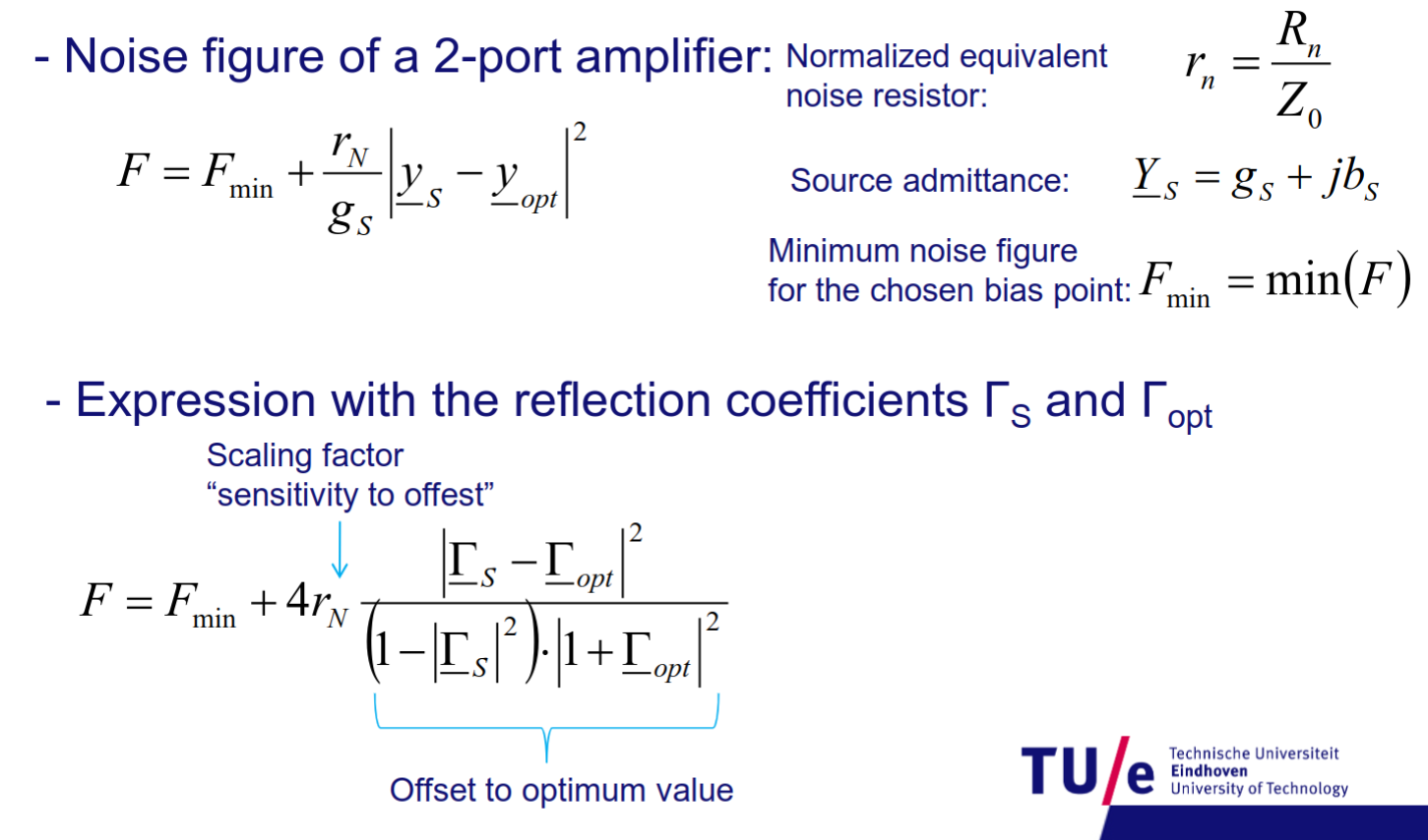
Value of
The values are in circles and we can calculate the center and the radius. The circles are called constant noise circles.
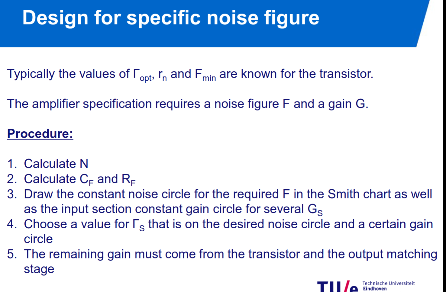
With the Noise figure parameter N defined as:
Basics of PA and Mixer Design (Power amplifiers and mixers)
5XTC0_Module_6_PAs_Mixers (1).pdf
Formulas
Signal-to-noise ratio (SNR):
Thermal noise power:
Noise figure (F):
Noise figure (dB):
Friis’ noise figure formula (cascaded stages):
Noise figure of an amplifier with reflection coefficients:
Noise figure parameter (N):
Constant noise circle radius:
Nonlinear output expression:
1 dB Compression Point: input/output power where gain is reduced by 1 dB from linear response
Second-order intercept point (IIP2): Extrapolated power where second-order products intersect with fundamental
Third-order intercept point (IIP3): Extrapolated input power where third-order products equal fundamental
Cascaded IIP3 formula:
Mixer output signal (RX - time domain):
Intermediate frequency (IF):
Mixer output signal (TX - time domain):
Upconverted frequency (TX):
Mixing in frequency domain:
Output power:
Optimum load resistance:
Maximum PA efficiency (Class A):
System level design
5XTC0_Module7_System_Design.pdf
Formulas
Signal-to-Noise Ratio (SNR)
Friis’ Formula for Cascaded Noise Figure
Cascaded IIP3 Formula
Output Power from Gain
Linear Dynamic Range (LDR)
Spurious Free Dynamic Range (SFDR)
Energy per Bit
Noise Power
Ratio
Receiver Sensitivity (in dBm)
with:
Shannon Capacity
Friis Radio Link Formula (Power at RX input)