5XTA0 Telecommunications Systems
- Area: Communications and Networking
- Topics: Modulation · Wireless Channel · Networks and Error Control
- Related courses: Communication 1 - 5ETC0 · Communication Theory - 5ETB0 · Components in Wireless Technologies - 5XTC0
Modulation Formats and Wireless Networks (Simon)
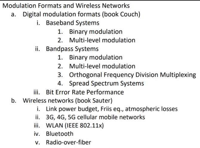
Digital modulation formats
Topic: Modulation
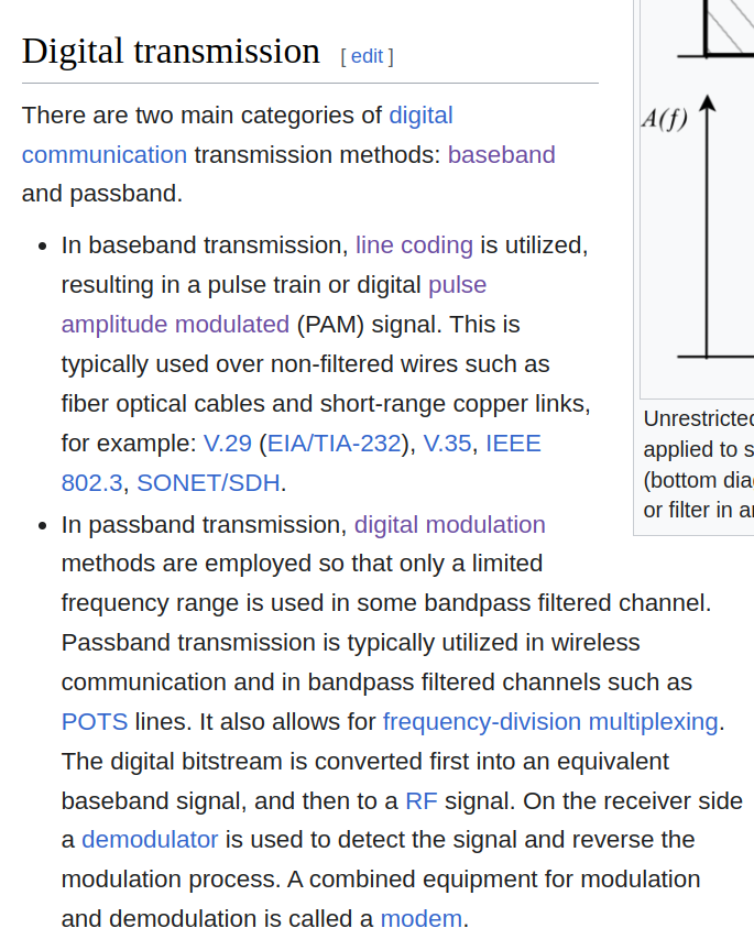
why linecoding for baseband
Linecoding generally doesn’t work well on bandpass signals for a few key reasons:
-
Spectral mismatch: Linecodes are designed for baseband transmission, while bandpass signals occupy a specific frequency band away from DC. This fundamental mismatch in spectral characteristics makes direct application of linecoding ineffective.
-
Loss of low-frequency components: Bandpass signals inherently lack the low-frequency components that many linecodes rely on for proper decoding and clock recovery.
-
Interference with carrier: Applying linecoding directly to a bandpass signal would interfere with the carrier frequency, potentially distorting the signal and making recovery difficult.
-
Modulation incompatibility: Bandpass signals often use specific modulation schemes (like QAM or PSK) that are incompatible with traditional linecoding techniques.
-
Increased bandwidth requirements: Attempting to apply linecoding to a bandpass signal would likely increase the bandwidth requirements beyond what’s typically allocated for bandpass transmission.
Instead of linecoding, bandpass signals typically use modulation techniques specifically designed for their frequency characteristics. These methods allow for efficient use of the available bandwidth while maintaining signal integrity.
Would you like me to elaborate on any of these points or discuss alternative techniques used for bandpass signals?
baseband vs bandpass example
I understand this can be confusing, and I’ll try to explain it in a simple way. Don’t worry, you’re not stupid - these concepts can be tricky! Let’s break it down with an analogy and then a more technical example.
Analogy: Radio Stations
Think of baseband and bandpass like different types of radio stations:
-
Baseband (AM radio):
- Broadcasts at a low frequency
- Takes up a small range of frequencies near zero
- Can only fit one station in this space
-
Bandpass (FM radio):
- Broadcasts at higher frequencies
- Each station occupies a specific “band” of frequencies
- Multiple stations can exist side by side at different frequency bands
Technical Example: Sending a Simple Message
Let’s say we want to send the binary message “1010” (representing some data).
Baseband Modulation:
- We might represent this directly:
- ‘1’ as a high voltage
- ‘0’ as a low voltage
- The signal would look like: high, low, high, low
- This signal contains frequencies starting from 0 Hz (DC) up to some maximum
Bandpass Modulation:
- We start with a carrier wave (let’s say at 100 MHz)
- We modify this carrier based on our data:
- For ‘1’, we might increase the amplitude
- For ‘0’, we might decrease the amplitude
- The resulting signal is centered around 100 MHz, not at 0 Hz
Key Differences:
-
Frequency range:
- Baseband: Starts at 0 Hz
- Bandpass: Centered around a specific frequency (like 100 MHz)
-
Signal shape:
- Baseband: Directly represents the data
- Bandpass: Data modifies a carrier wave
-
Multiple channels:
- Baseband: Typically one channel in the available spectrum
- Bandpass: Can have multiple channels at different frequencies
-
Applications:
- Baseband: Often used in wired communications (like Ethernet)
- Bandpass: Common in wireless communications (like Wi-Fi, cellular)
Does this help clarify the differences? Would you like me to expand on any part of this explanation?
Baseband Systems
Line code - Wikipedia
Baseband uses lincoding for modulation
which results in PAM
Pulse-amplitude modulation - Wikipedia
Baseband is used in wire transmission
Baseband modulation techniques encode information directly as the amplitude, width, or position of a pulse. They do not utilize a sinusoidal carrier. Some of these modulation schemes are known by the acronyms PWM ( pulse width modulation), PPM ( pulse position modulation), and PAM ( pulse amplitude modulation).
theory - Baseband vs Passband modulation - Signal Processing Stack Exchange
low frequency signal…
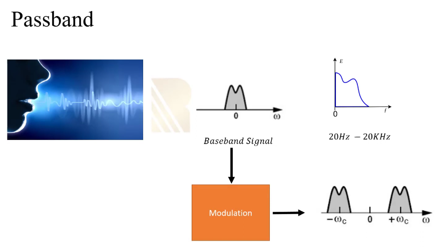
A modulated baseband signal is called a passband signal.
Baseband is just a message signal…
What is a Baseband Equivalent Signal in Communications? - YouTube
Baseband - Wikipedia
- passband signal in frequency domain centered at
- to sample it we need nyquist criteria:
- which may be too large frequency…
- where baseband comes in so we only reconstruct around that signal
- frequency domain has duplicity in negative domain, we ignore it and take only the positive through Fourier transfer
and shift to 0… - now when we sample at nyquest criteria its a much lower frequency range (beauty of baseband).
- we moved passband to baseband
Baseband: no signal modulation; Bandpass: modulation.
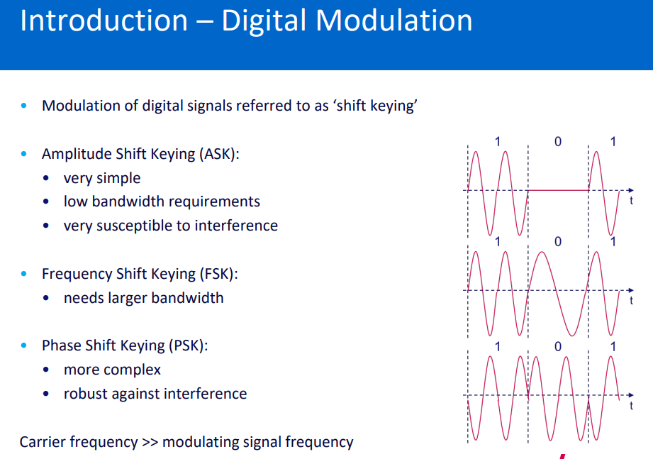
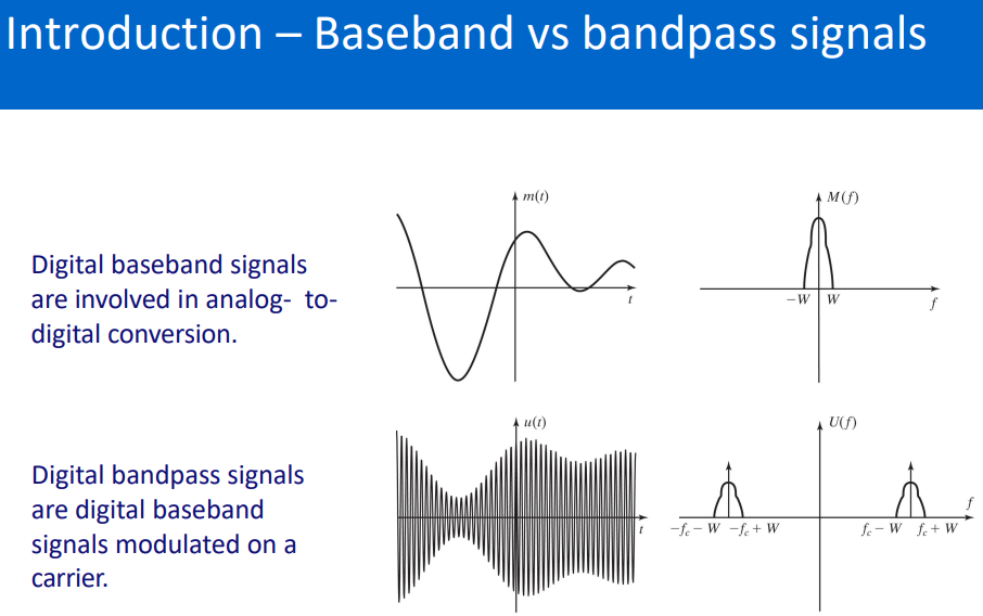
Baseband Signaling (fibre optic): Binary Modulation, Multi-level modulation (multi-level PAM) : Just PSD stuff line coding so multilevel is like intro telecom.
Communication 1 - 5ETC0 > Linecodes and their spectras
Bandpass Systems
Band-pass filter - Wikipedia
Passband - Wikipedia
Modulation - Wikipedia
Bandpass being at a lot higher frequencies due to carry signal applied to the message signal(the baseband signal). Making it a lot higher frequency for the purpose of antenna practicality.
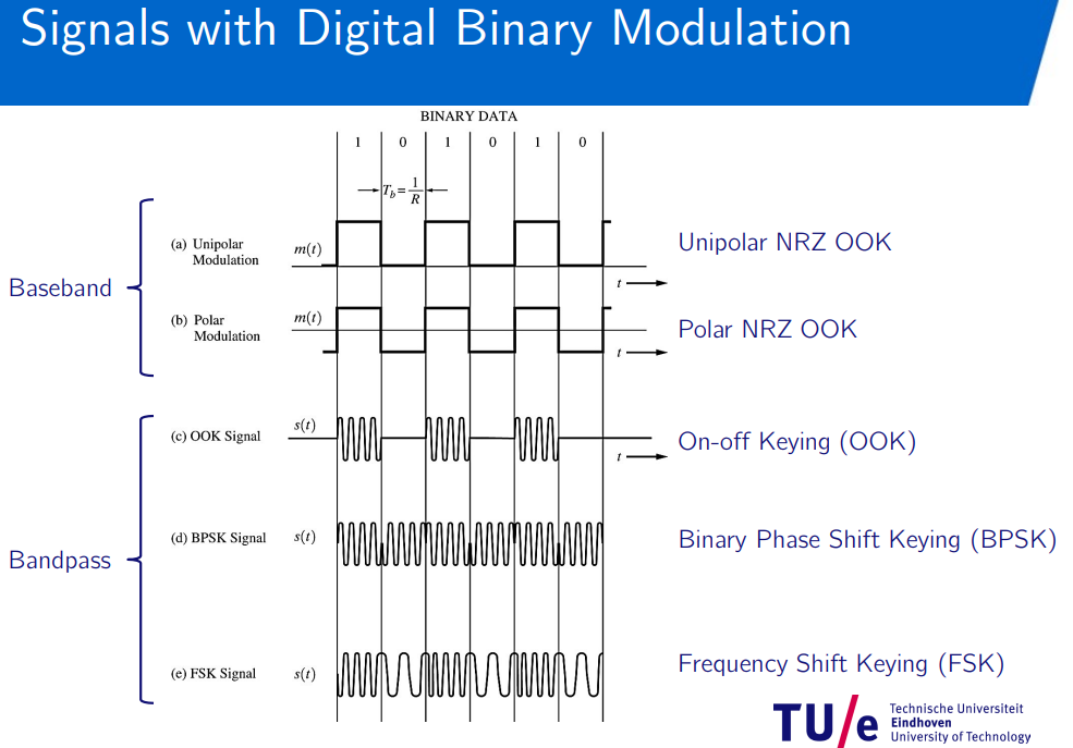
Binary Modulation
On–off keying - Wikipedia
Amplitude-shift keying - Wikipedia
Phase-shift keying - Wikipedia
Frequency-shift keying - Wikipedia
Passband Modulation
Understanding Amplitude Shift Keying - YouTube
Understanding Frequency Shift Keying - YouTube
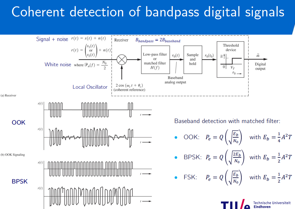
Coherent detection (OOK, BPSK(sync detection), FSK)
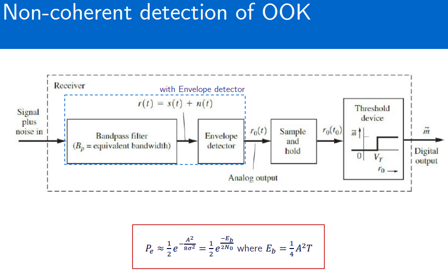
Non-coherent detection (OOK, FSK, DPSK)
In coherent detection, the receiver has precise knowledge of the carrier signal’s phase and frequency.
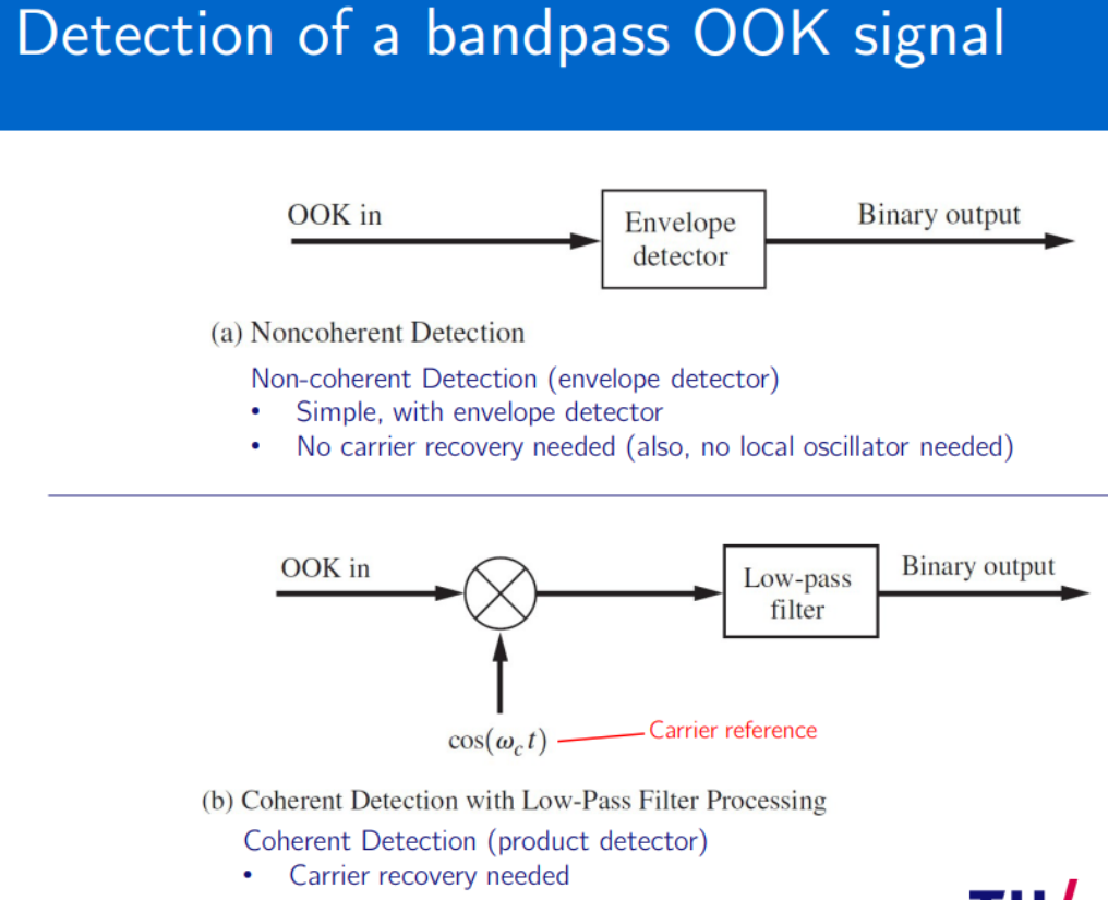
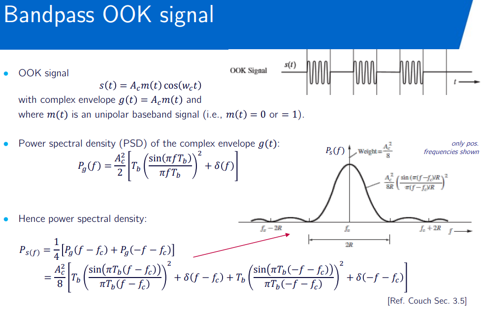
OOK (On-off Keying)(Amplitude Shift Keying ASK)
bandpass waveform:
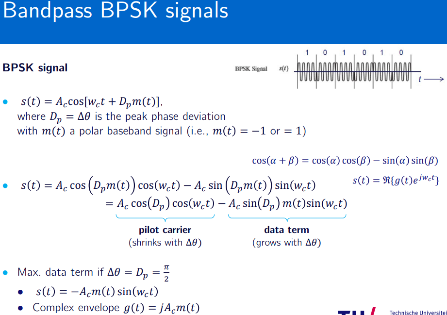
BPSK (Phase Shift Keying PSK)
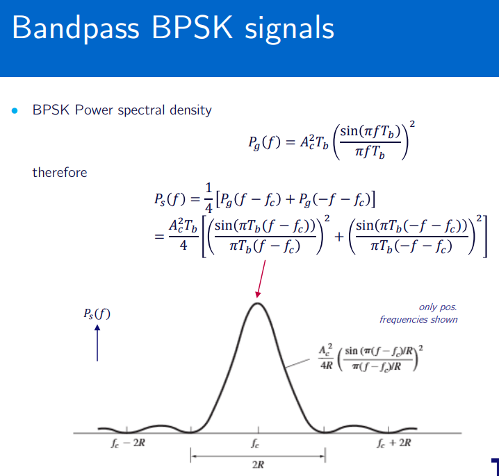
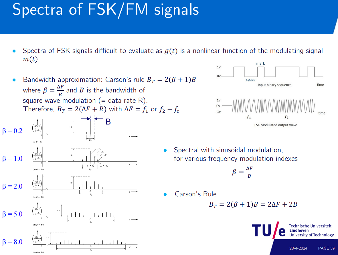
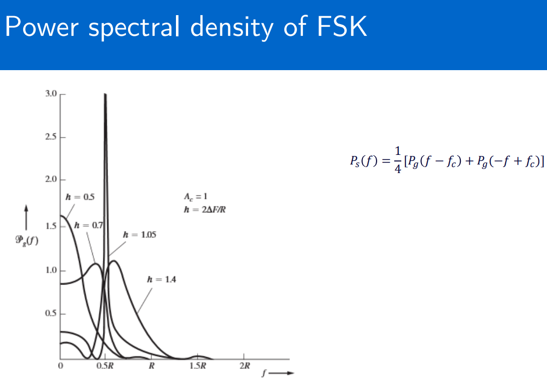
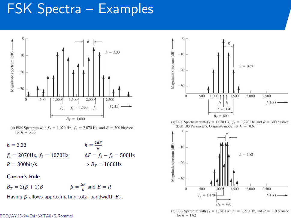
FSK (Frequency Shift Keying)
but for FSK
if sinc pulse
always use carsons rule for FSK.
requires approximation.
cosine roll-off:
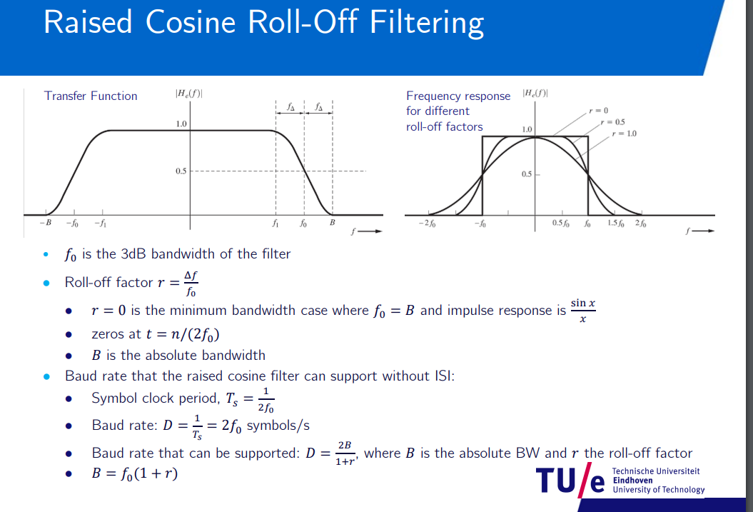
Binary Modulation
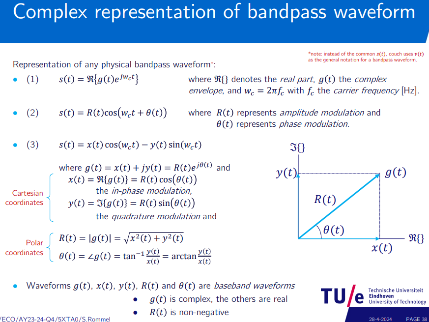
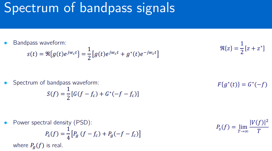
Bandpass Modulation Types
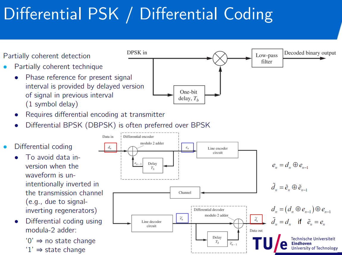
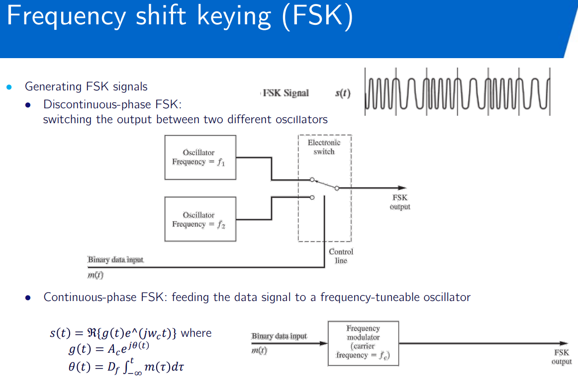
Detector Types
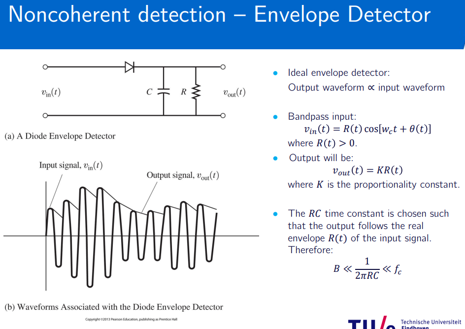
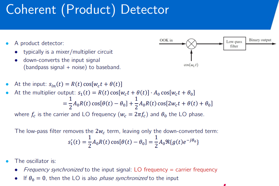
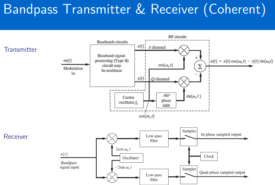
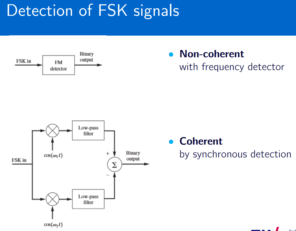
coherent: generated by same oscillator. non-coherent multiple oscillators.
For detection see envelope/product detectors. Converters convert bandpass to baseband.
Multilevel Modulation
Understanding Phase Shift Keying - YouTube
Quadrature amplitude modulation - Wikipedia
Phase-shift keying
modulation - Envelope behavior dIfference between QPSK, OQPSK and
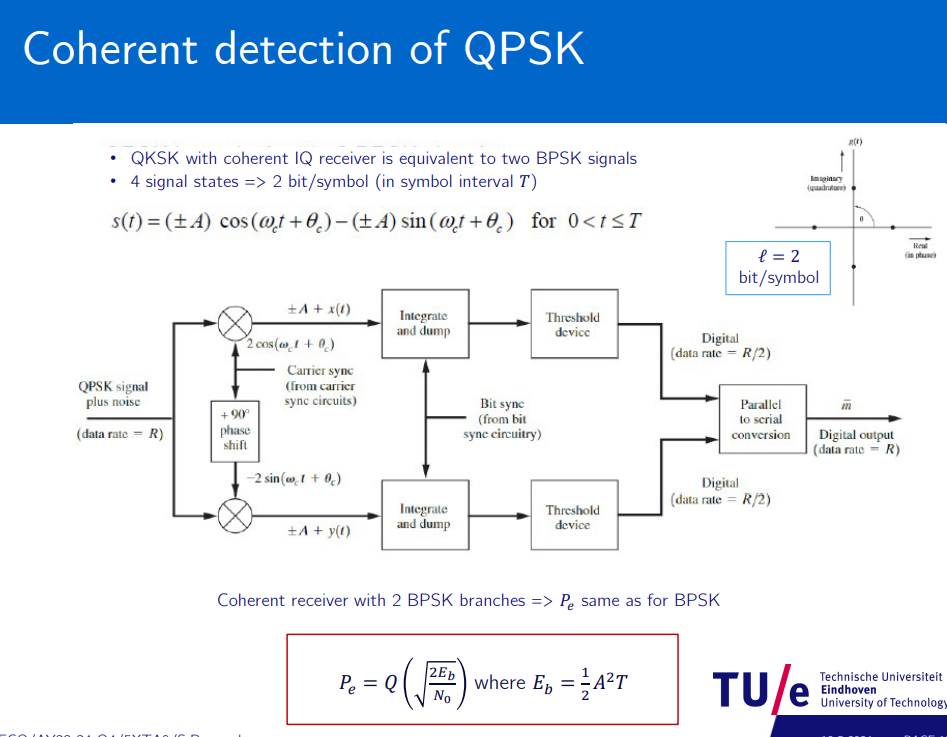
- Multi-level Phase Shift Keying (QPSK, M-PSK)
- Multi-level Quadrature Amplitude Modulation (M-QAM)
Q → Quaternary →levels →
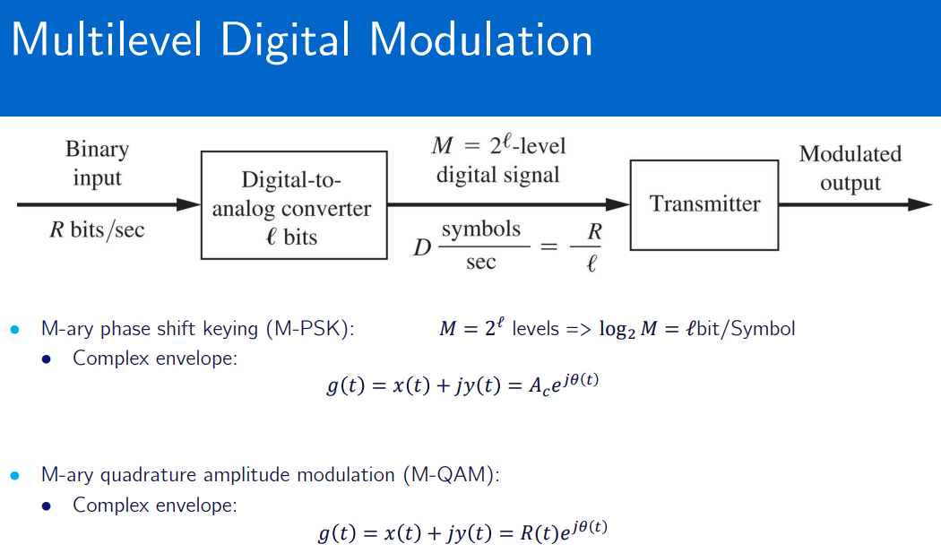
will primarly use
Constellation diagram
phase modulation: angles
amplitude modulation: distance from origin
transition between states: lines
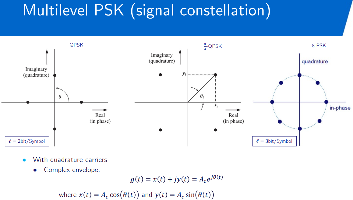
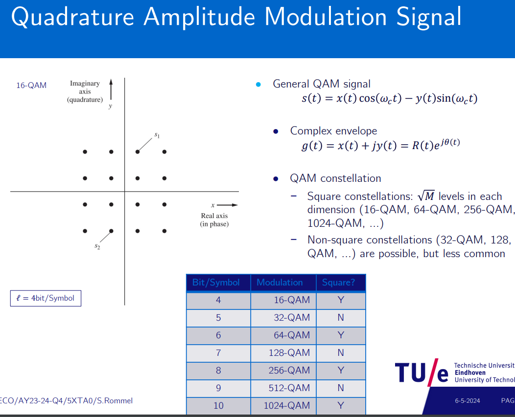
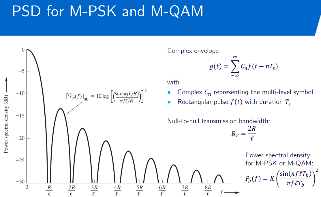
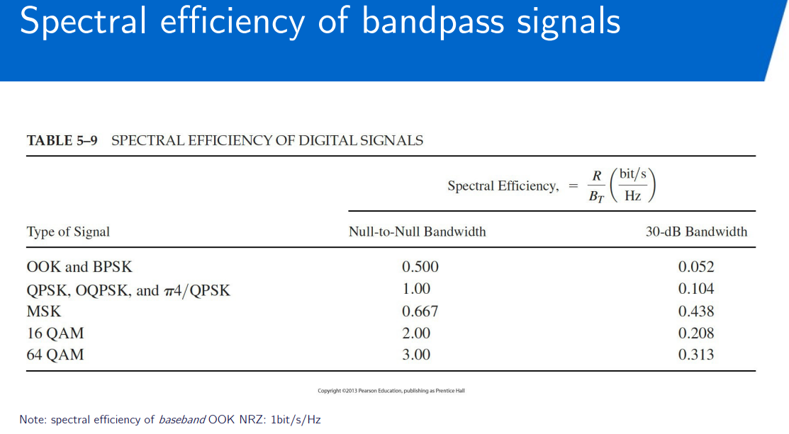
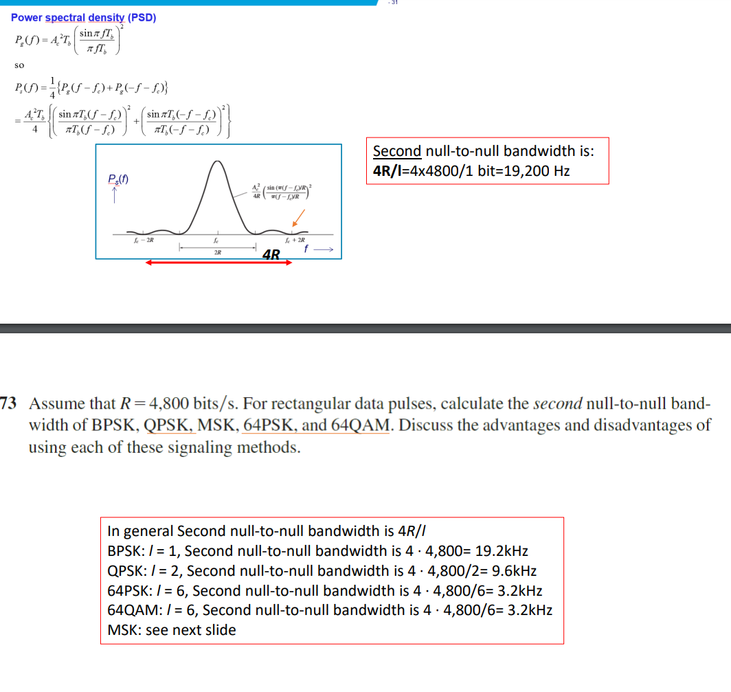
BPSK: Not bandwidth efficient but not sensitive to amplitude variation and requires only two decision points: binary 1 and 0 separated by 180 deg.
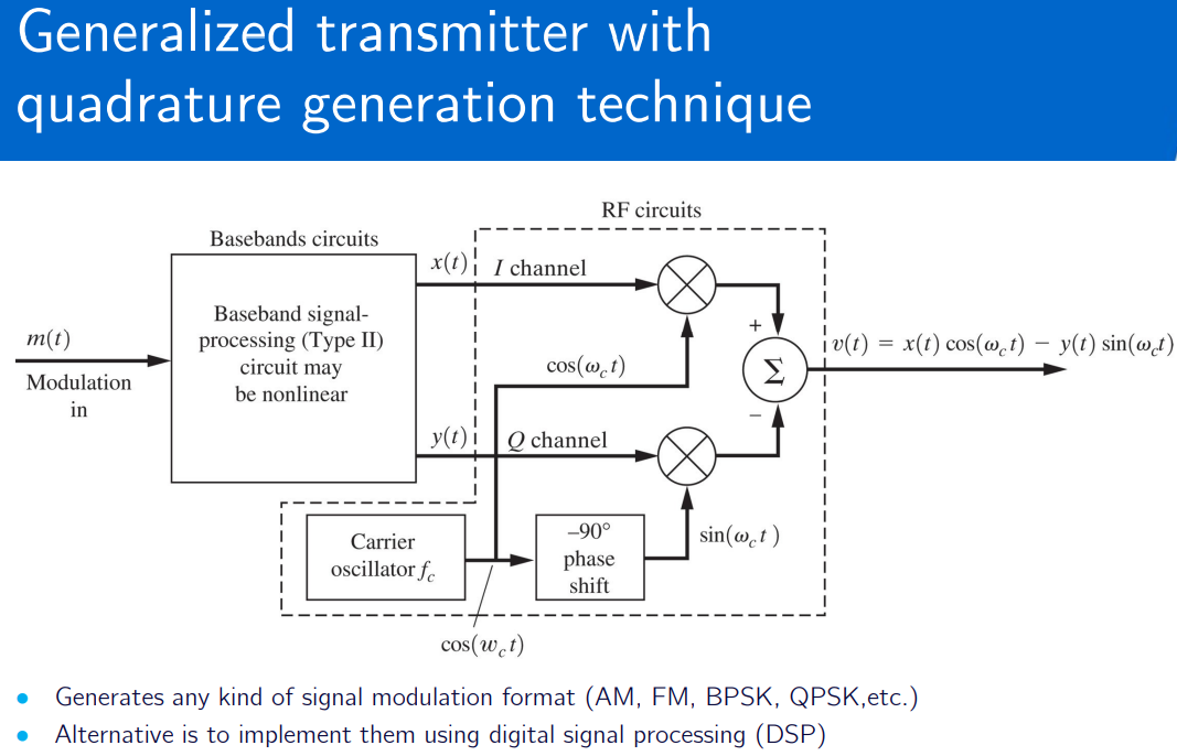
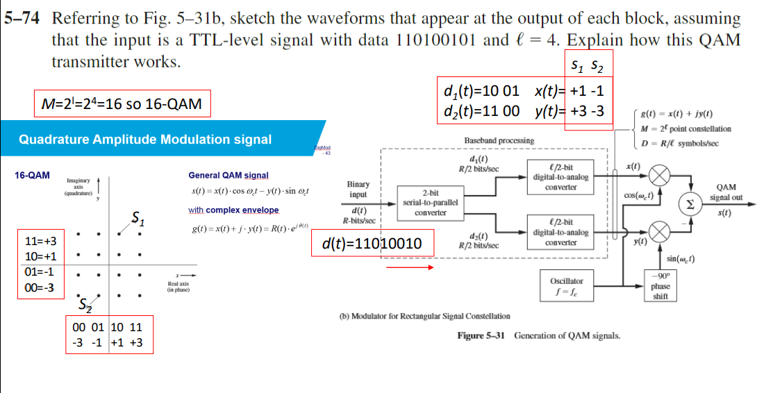
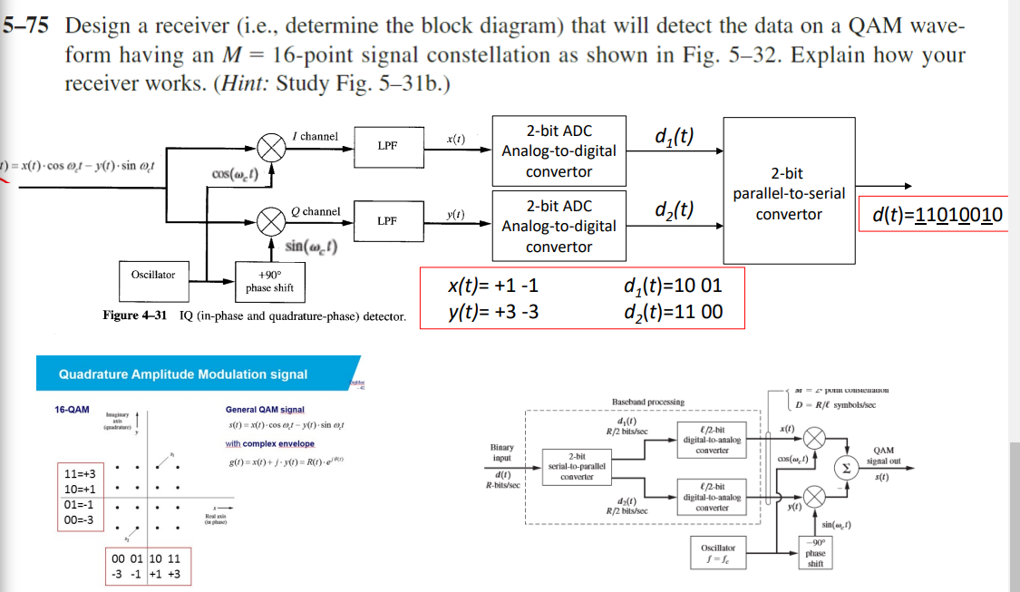
QPSK: More bandwidth efficient than BPSK but requires more decision points than BPSK. Has a complex carrier symbol with each level having 90 deg phase shift. Requires 4 decision points. Multilevel modulation formats: More bandwidth efficient in order to achieve the same data rate. However, higher order modulations are more complex to generate, e.g encoding and decoding bits, requiring more processing power and costly equipment.
Transmitter
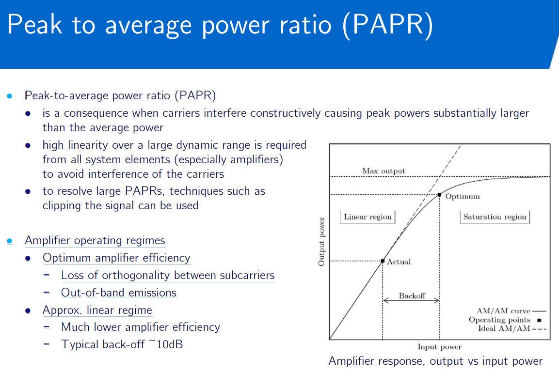
Orthogonal Frequency Division Multiplexing (OFDM)
- Principle: OFDM divides the available bandwidth into multiple orthogonal subcarriers, each modulated with a low bit rate signal.
- Orthogonality: Ensures that subcarriers do not interfere with each other, allowing for efficient spectrum usage.
type of digital transmission used in digital modulation for encoding digital (binary) data on multiple carrier frequencies.
OFDM Waveforms - YouTube
Orthogonal frequency-division multiplexing - Wikipedia
OFDM Network Optimization Using a QPSK Based on a Wind-Driven Genetic Algorithm - PMC
higher spectral efficiency than spread spectrum (other double sideband modulation schemes).
OFDM uses QPSK as a modulation scheme
used for wideband transmission
Sideband - Wikipedia
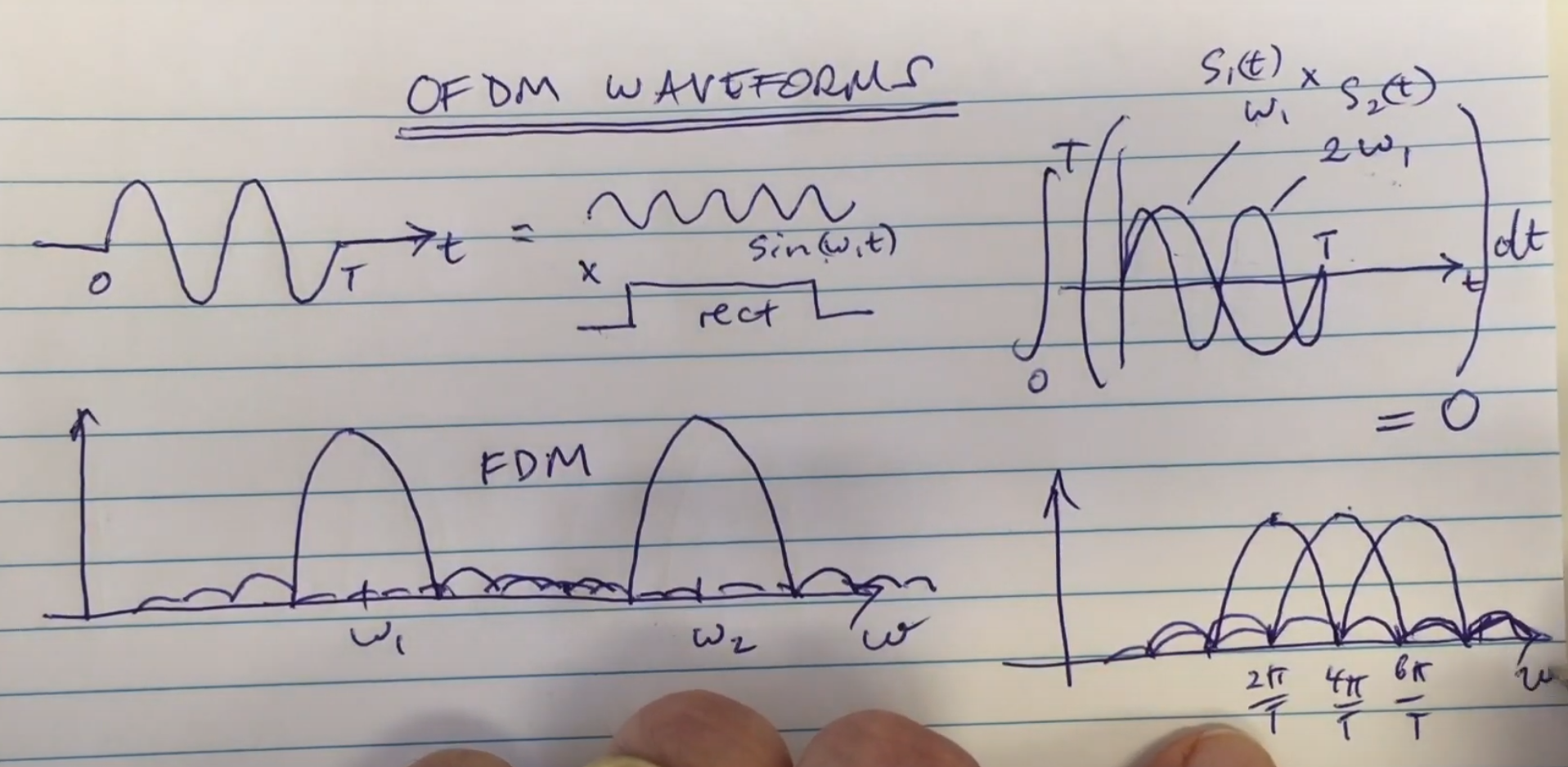
to fill more channels in the bandwidth
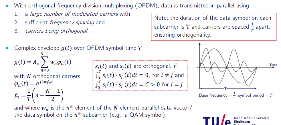
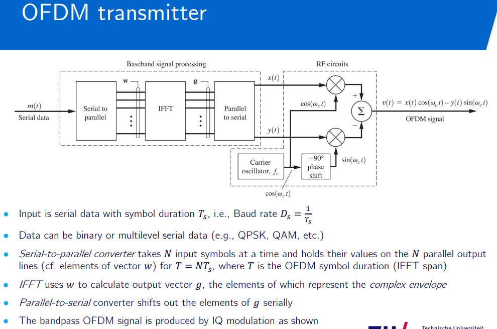
FFT: fast fourier transform
carrier spacing:
OFDM receiver: serial data recovered by: demodulating signal to produce I, Q; converting serial to parallel data; evaluating FFT; converting FFT from parallel to serial
null to null oduble that
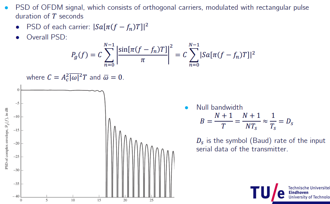
adapting signaling
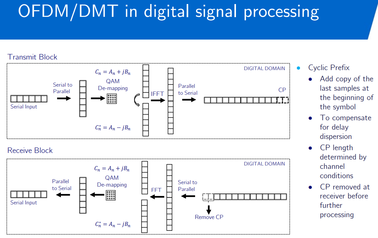
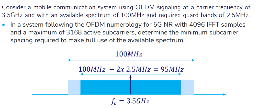
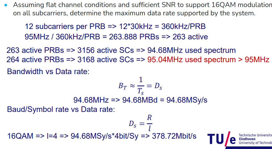
In adaptive Bit-loading the number of bits that can be transmitted in each subcarrier is determined by the SNR on the subcarrier. According to Shannon’s theorem we should be able to get more bps/Hz using subcarriers that have higher SNR. Data rate can be varied per carrier.
Spread Spectrum Systems
Spread spectrum - Wikipedia
spreading the signal over a large frequency band.
use bandwidth maintaining signal power: good for military low signal transmission.
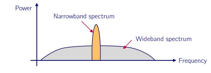
Spread spectrum systems:
Direct sequence (DSSS): rapid phase transition to the data to make it larger in bandwidth. (noise like signal masking).
DSSS - Direct Sequence Spread Spectrum - YouTube
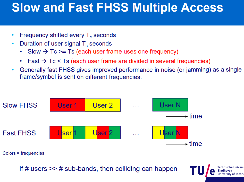
Frequency Hopping (FHSS): narrow band signal jump in random narrow bands within a larger bandwidth. (doesn’t spread spectrum). Hops around the band to avoid jammers(random noise targeted to specific band).
FHSS - Frequency Hopping Spread Spectrum - YouTube
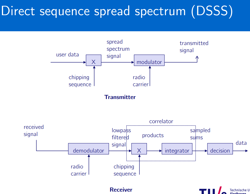
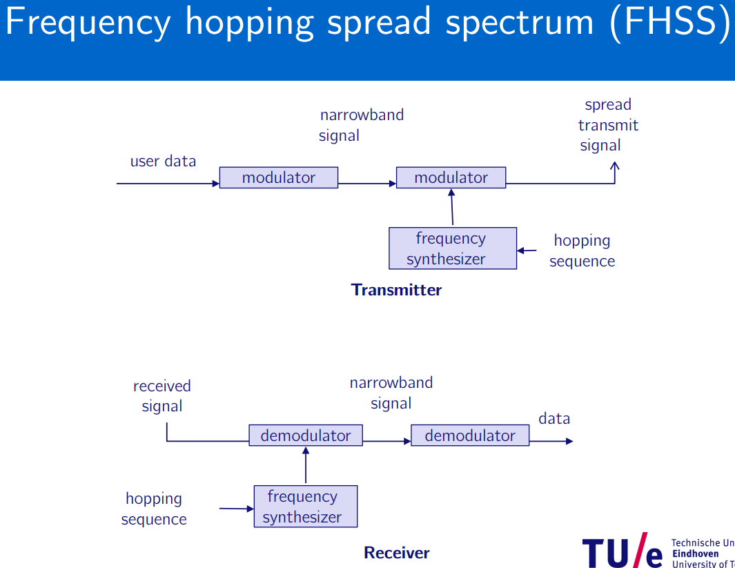
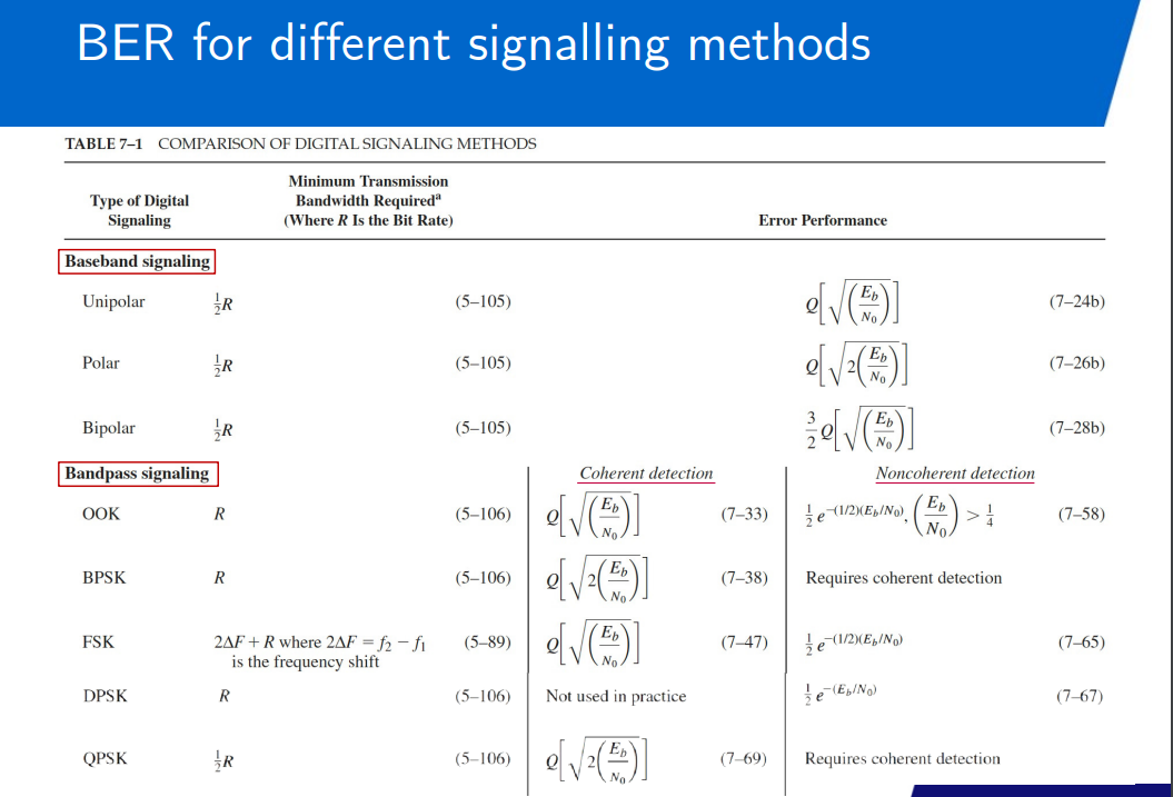
Bit Error Rate performance (BER)
Bit error rate - Wikipedia
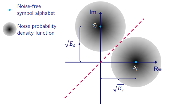
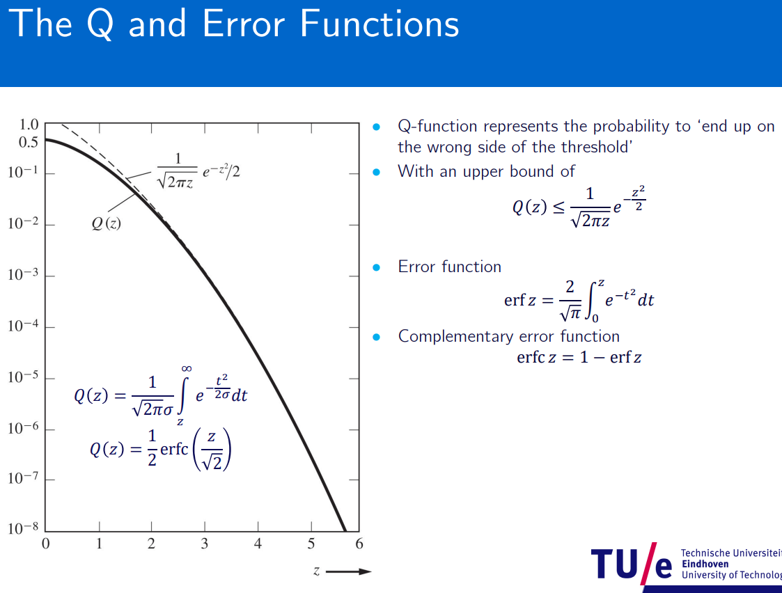
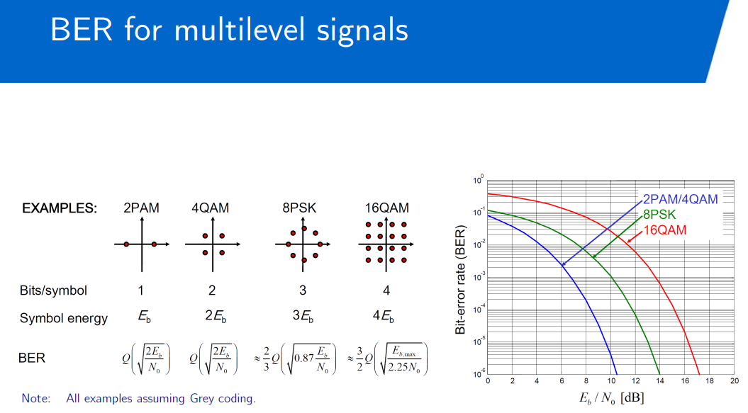
Gaussian probability of error occurring.
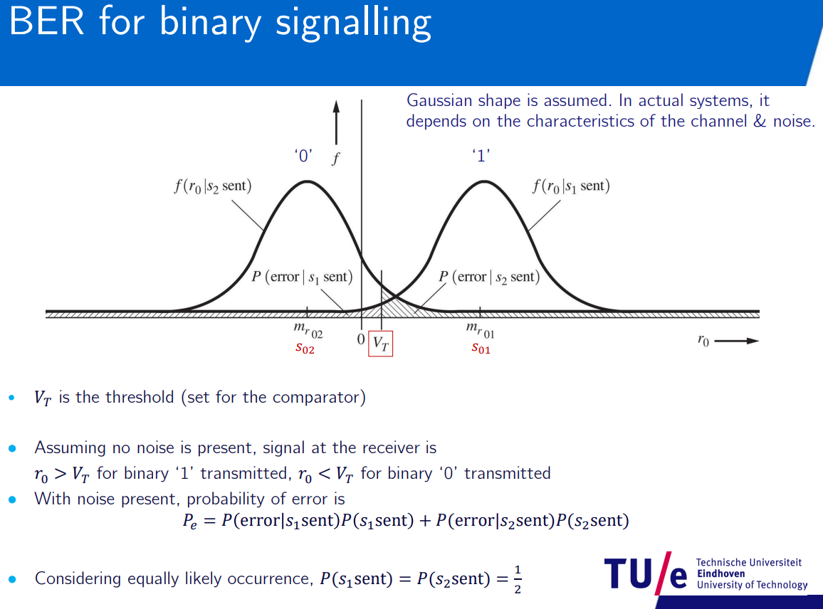
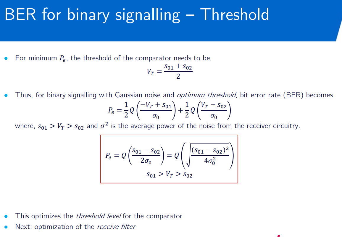
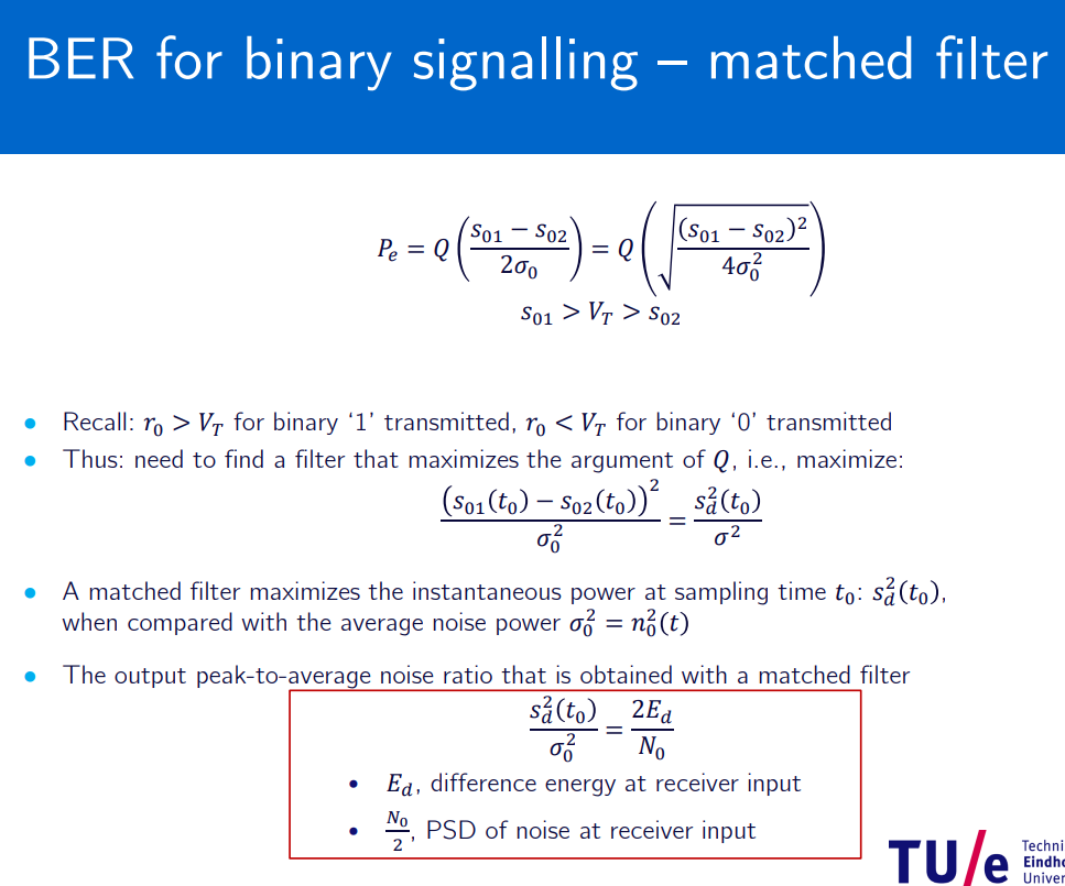
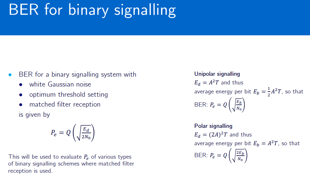
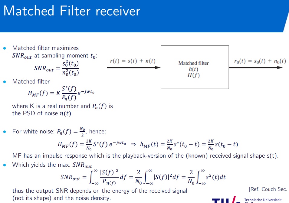
matched filter reception:
NON-COHERENT DETECTION
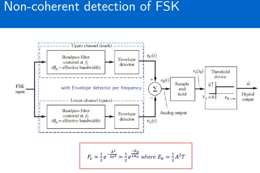
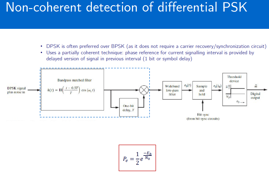
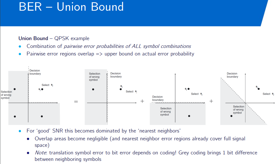
Union Bounds: serves as upper bound to error probability with complex modulation with multiple alternatives, since we cant calculate the exact symbol error rate.
Wireless networks
Topic: Wireless Channel
Introduction to Wireless Networks
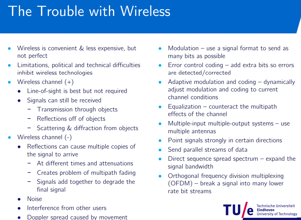
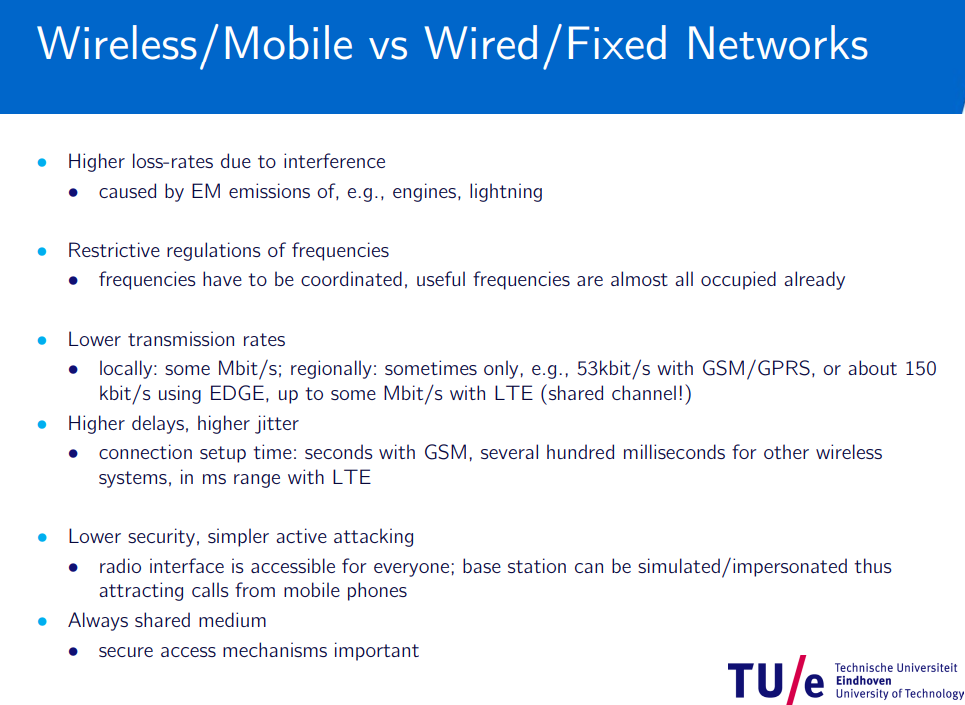
Antennas, Link power budget, Atmospheric losses
Inside Wireless: Antenna Gain - YouTube
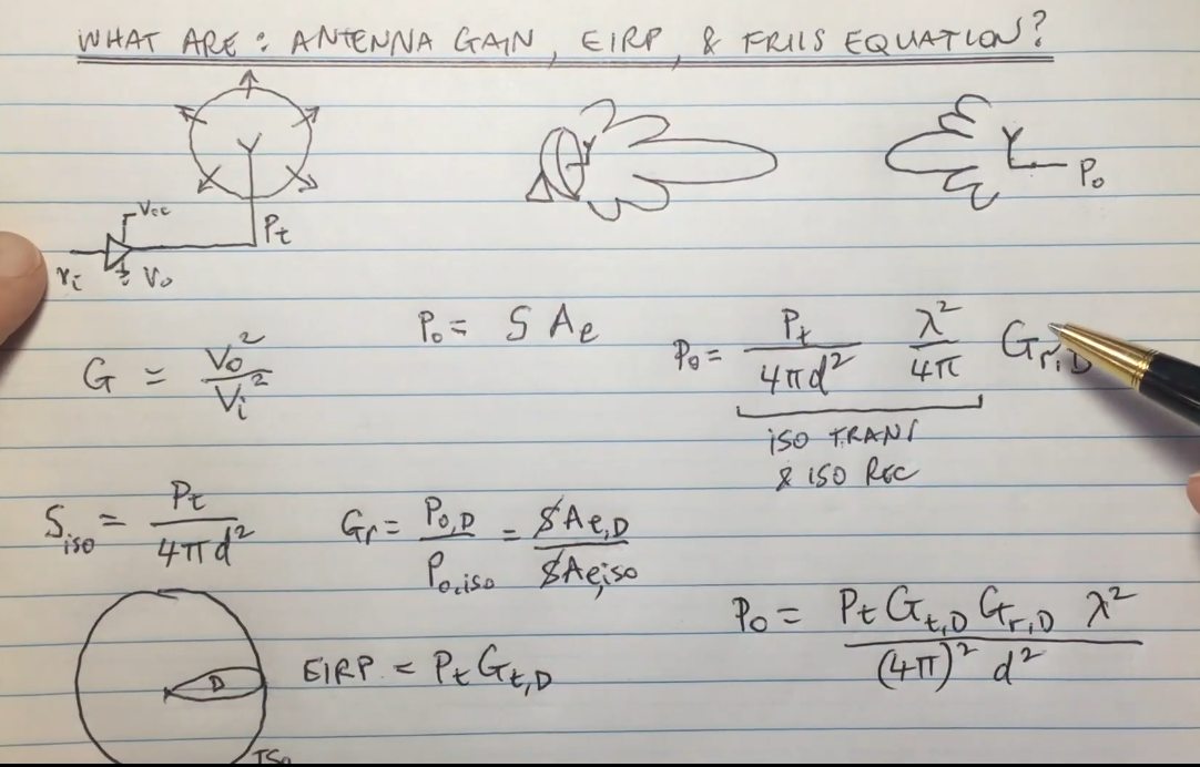
What are Antenna Gain, EIRP, and Friis Equation? - YouTube
-
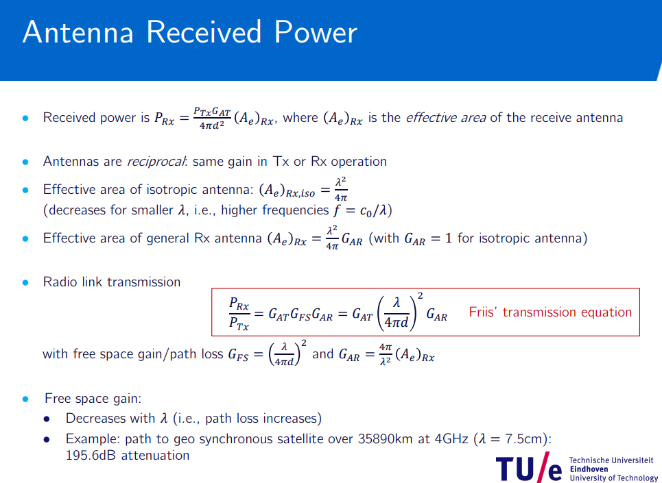
Friis equation for gain:
. -
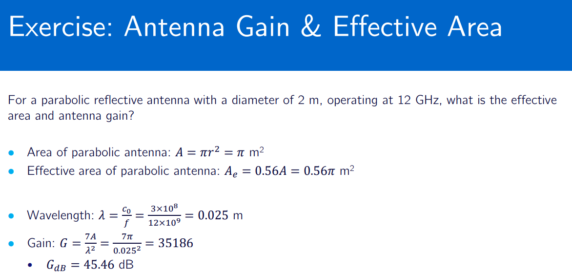
isotropic gain if at receiver or transmitter is = 1
-
Isotropic Radiator: Theoretical antenna radiating equally in all directions.
-
Beam Width: Measure of directivity of an antenna.
-
Sidelobes and Nulls: Extra energy outside the main lobe and very low energy between the main lobe and sidelobes respectively.
-
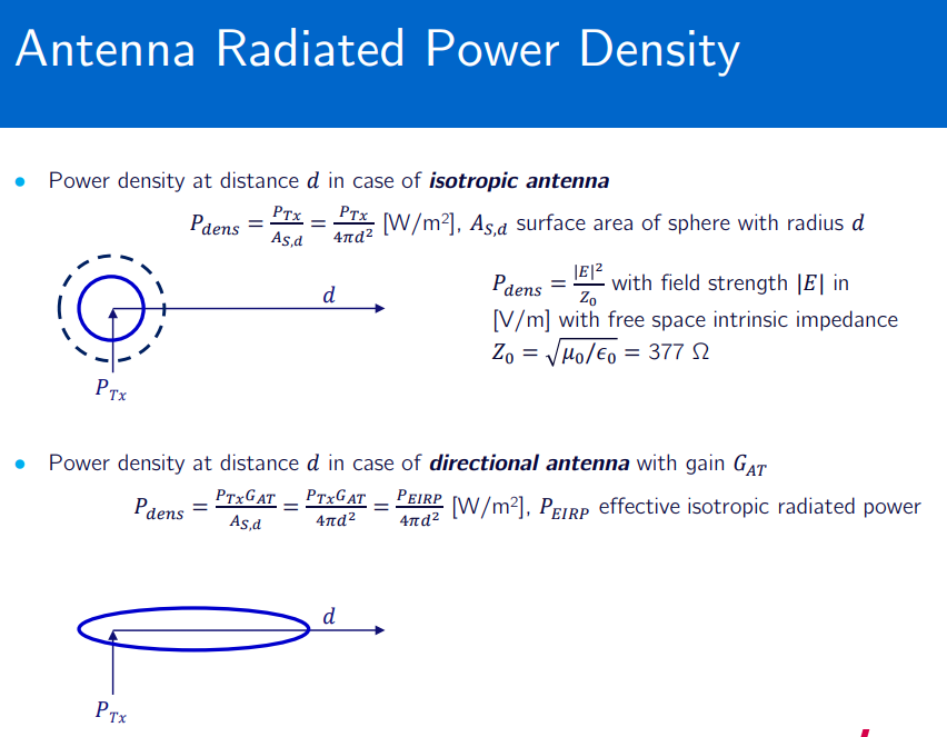
Antenna Power Density (Isotropic):
-
Antenna Gain multiply it for directional antennas.
-
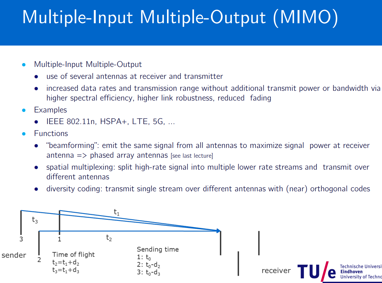
- Wireless channel ALWAYS shared channel, needs sharing protocol.
- multiplexing to optimize the channel capacity.
- space,time,frequency,code,polarization multiplexing
- OFDM is time AND frequency multiplexing for example…
- DSSS code multiplexing where one spectrum used (spread spectrum)
multipath propagation
Multipath Propagation:
-
Occurs when transmitted signals take multiple paths to reach the receiver due to reflections, diffractions, and scattering from obstacles like buildings, trees, and other structures.
Impact on Quality: -
Causes constructive and destructive interference, leading to signal fading, distortion, and inter-symbol interference.
-
Can result in poor signal quality, reduced data rates, and increased error rates.
Reducing the Impact:
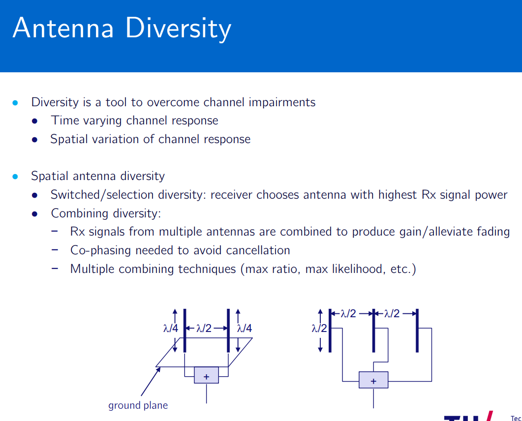
- Diversity Techniques: Use of multiple antennas (spatial diversity) or multiple frequencies (frequency diversity) to combine multiple received signals and mitigate fading.
- Equalization: Signal processing techniques that compensate for the time dispersion caused by multipath propagation.
- Error Correction: Implementing error correction codes to detect and correct errors caused by multipath effects.
- Adaptive Modulation and Coding (AMC): Adjusts the modulation scheme and coding rate based on the channel conditions to optimize data transmission.
Cellular Networks 1G, 2G, 3G, 4G (LTE), 5G
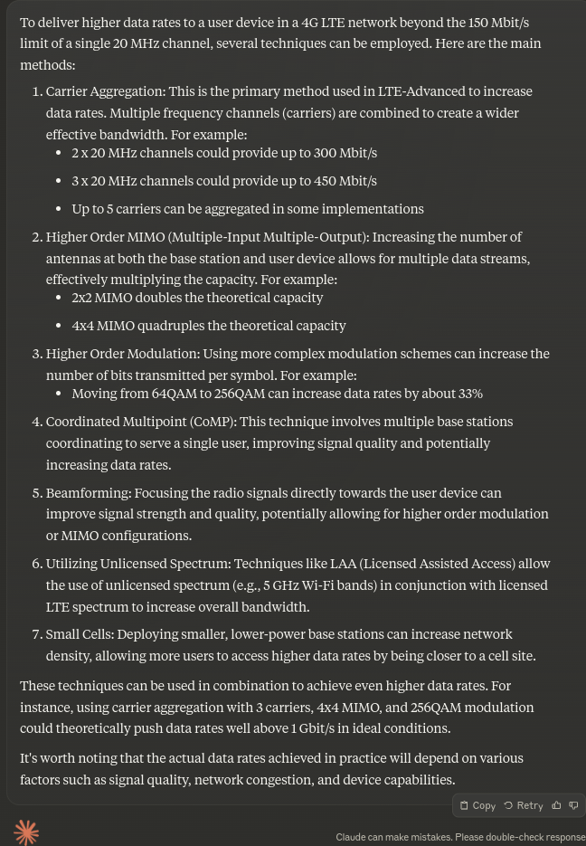
When a user requests for access to a LTE network, mutual authentication between the user and the network is conducted using EPS AKA procedure. An MME, upon receipt of such request, identifies the user using his/her IMSI and requests authentication vector(s) (AVs) from an HSS
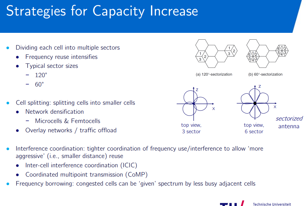
What are the advantages and disadvantages of cellular systems comprised of small cells? - Quora
Beamforming - Wikipedia
increased capacity, better coverage, enhanced data rates
increased interference, costs, complex
Impact of Mobility:
- Signal Fading: Rapid changes in signal strength due to movement, causing fluctuations in connection quality.
- Handover Issues: Frequent handovers can lead to dropped connections or temporary loss of service.
- Doppler Shift: Movement at high speeds can cause frequency shifts, affecting communication quality.
- Latency Variations: Variations in latency as the user moves can impact real-time applications like voice or video calls.
LTE (telecommunication) - Wikipedia
Cellular network - Wikipedia
- High frequency for capacity
- Low frequency for IoT and ultrareliable communications
Local and Personal Area Networks
Radio over fiber (RoF) or RF over fiber (RFoF) refers to a technology whereby light is modulated by a radio frequency signal and transmitted over an optical fiber link.
Radio over fiber - Wikipedia
Wireless LAN - Wikipedia
Bluetooth - Wikipedia
Carrier-sense multiple access with collision avoidance - Wikipedia
Multiple access & scheduling - ALOHA protocol
ALOHAnet - Wikipedia
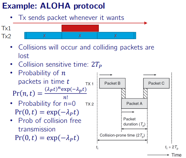
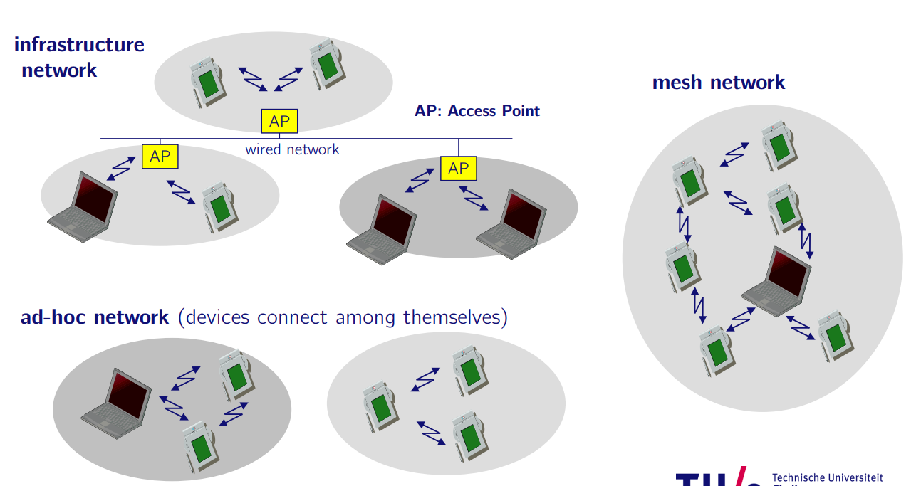
- Distributed Coordination Function (DCF) • Also known as CSMA/CA (Carrier Sense Multiple Access with Collision Avoidance)
- Local and Personal Area Networks • WLAN (IEEE 802.11x) • Bluetooth, Zigbee, etc.
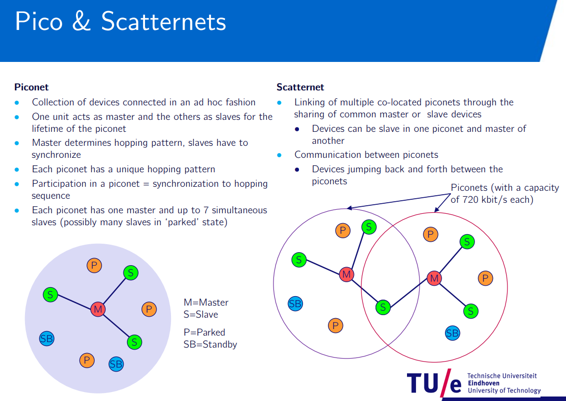
Scatternet - Wikipedia
Wireless ad hoc network - Wikipedia
MAC Technologies and Fixed Networks (Eduward)
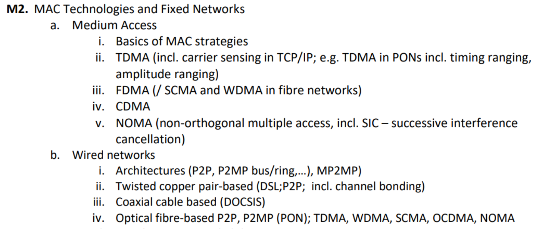
Medium Access
Topic: Networks and Error Control
Basics of MAC Strategies
media access (MAC) protocol for multi user communication.
media access control:
- Multiplexing (‘point-to-point’ communication)
- Multiple Access (‘multipoint-to-point’ communication)
multiplexing
Multiplexing
- Permanent sender-receiver connections.
- Receivers optimized for specific signals.
- Data can be continuous or packet-based, needing synchronization.
- Channels defined by physical parameters (e.g., time, frequency).
multiple access
Channel access method - Multiple stations access and share one channel.
- Receivers handle varying transmissions and select the correct one.
- Transmission starts with a preamble for synchronization.
- Examples include Ethernet and cellular systems.
- MAC differs from MUX but both manage channel access.
- Stations are logically separated by time, frequency, or code to avoid collisions.
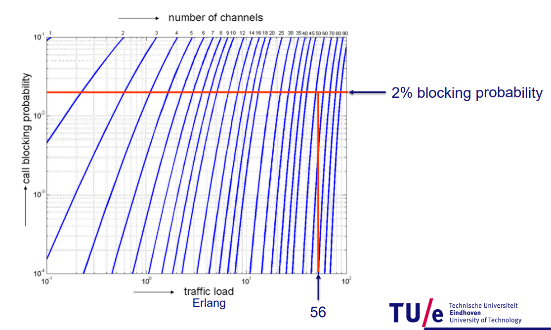
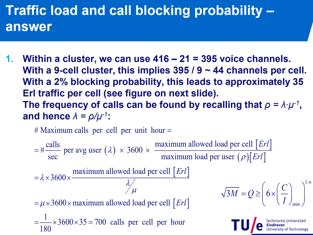
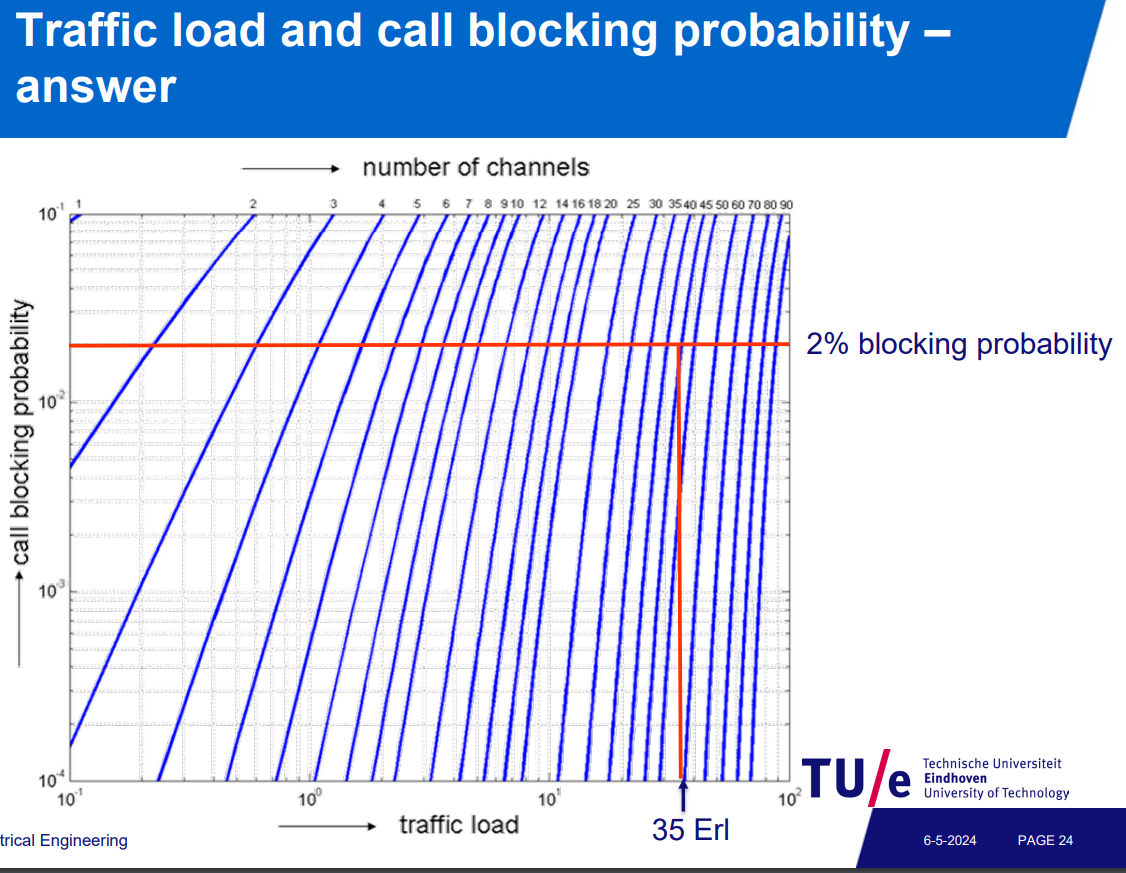
erlang-b
Erlang (unit)
Erlangs B-formule
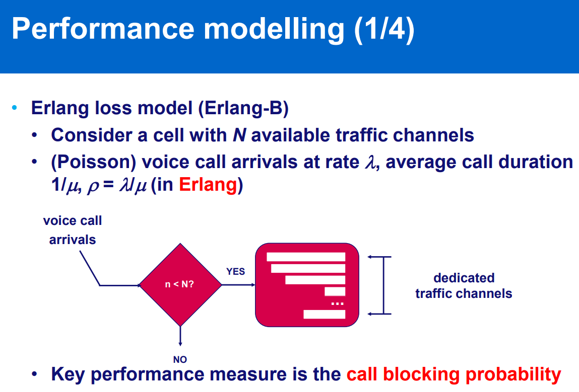
erlang loss model: queuing system, describes the stochastic behavior of the number of customers receiving service at a service center
Erlang-B (Loss) model: to get a certain blocking probability, channel number and/or load should be adjusted.
N-number of channels available
you can increase channels or decrease the size of network (coverage)
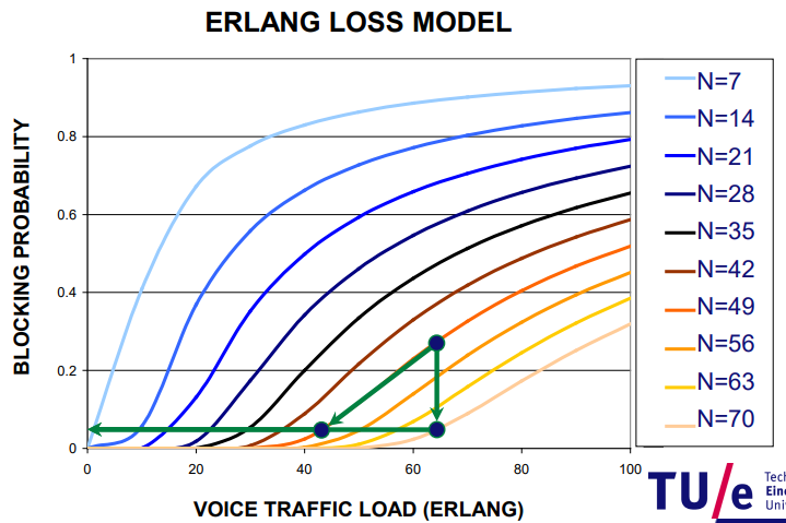
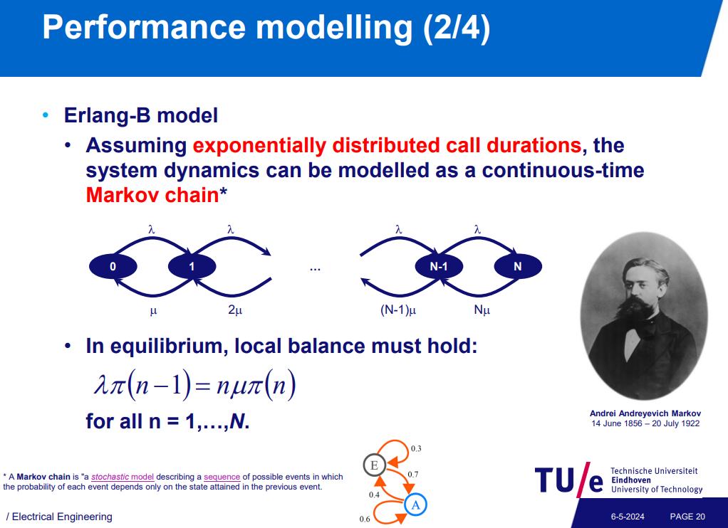
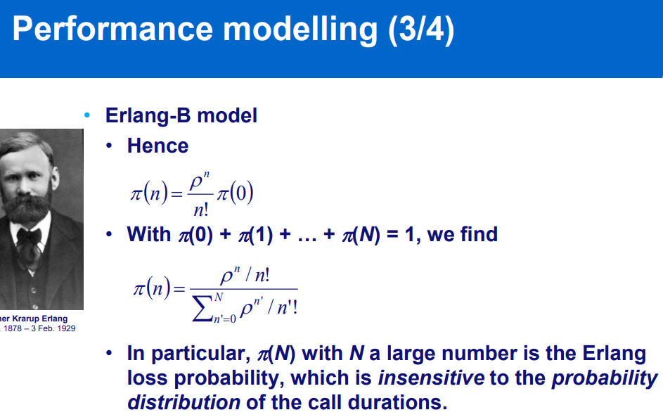
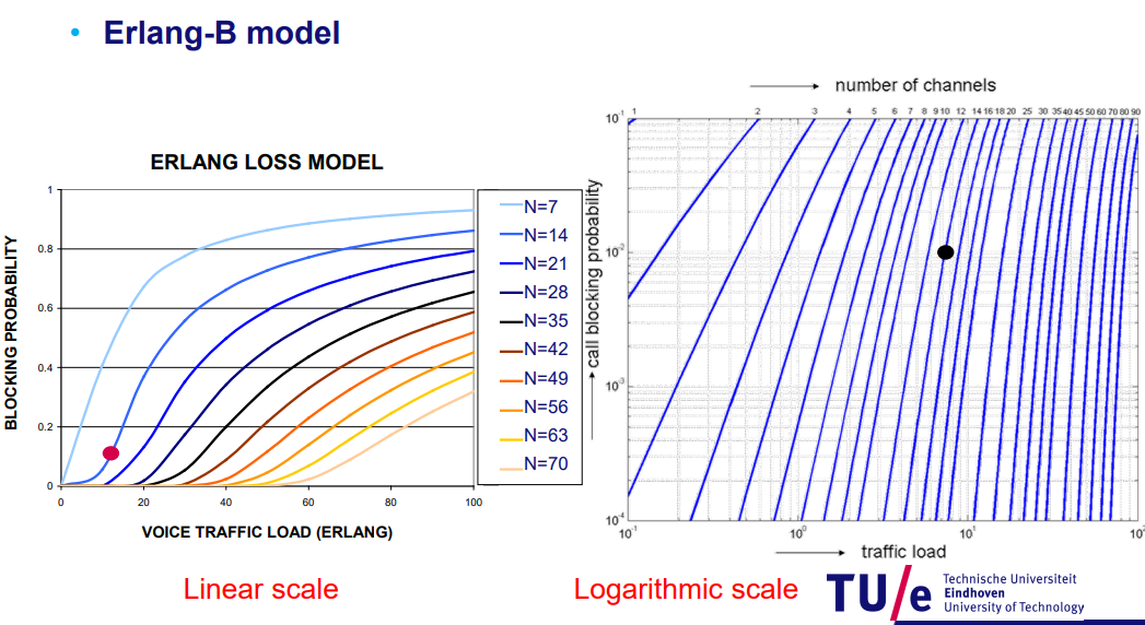
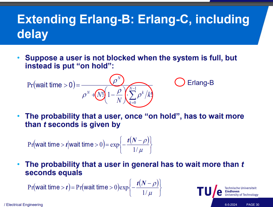
erlang graph reading
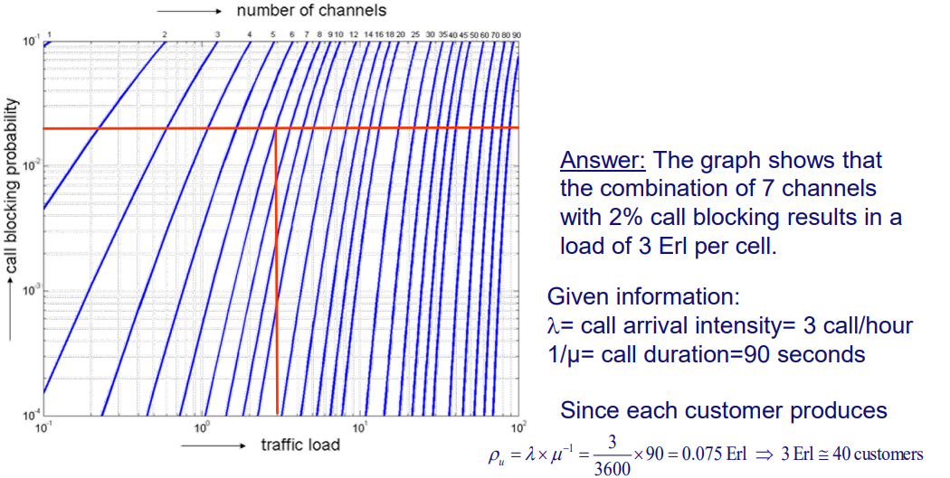
Erlang-C instead of block → on hold
he see here that we get
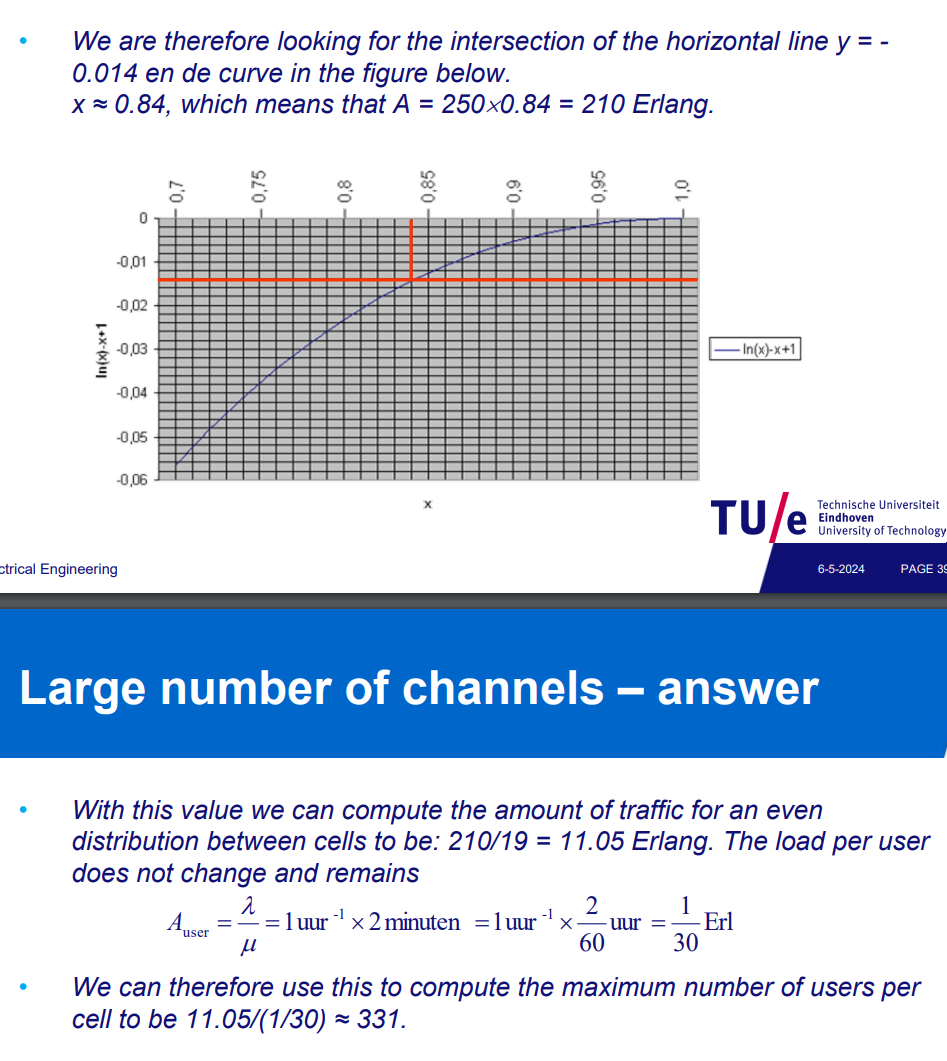
Total Call Duration (hours): Traffic Load:
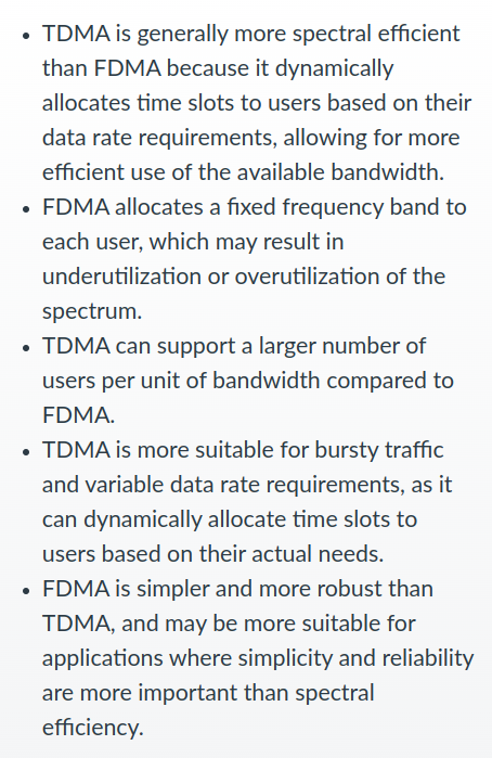
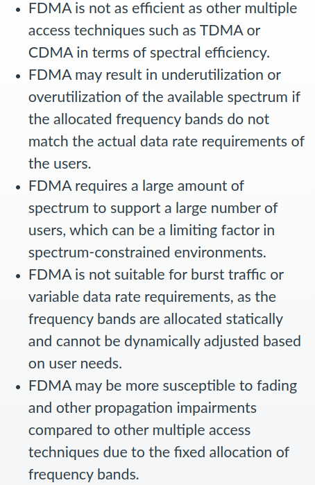
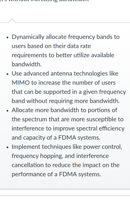
FDMA (/ SCMA and WDMA in fibre networks)
Subcarrier multiplexing - Wikipedia
Wavelength-division multiplexing - Wikipedia
Frequency Division Multiple Access (FDMA) Techniques
Channelization Protocols
Frequency-division multiple access - Wikipedia
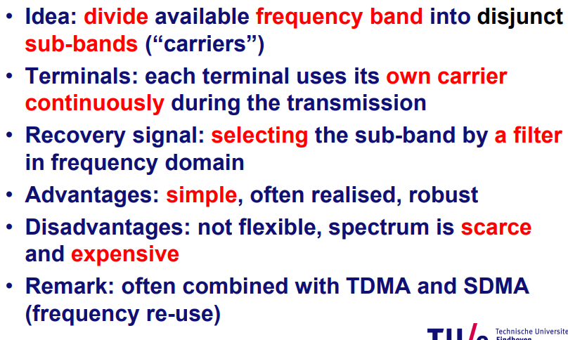
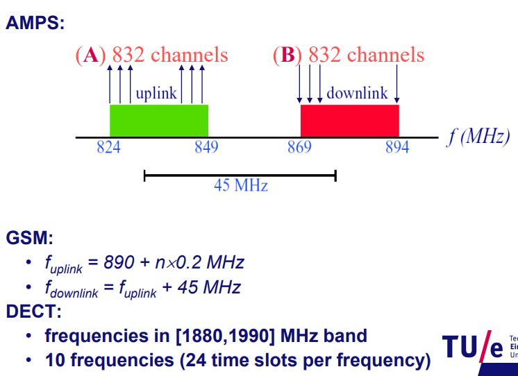
Frequency Division Duplex: FDD: to communicate between stations
The communication going from a satellite to ground is called downlink, and when it is going from ground to a satellite it is called uplink
Frequency-Division Duplex (FDD):
- FDD uses separate frequency bands for upstream and downstream communications.
- Each direction has its own dedicated frequency band, allowing simultaneous bi-directional communication.
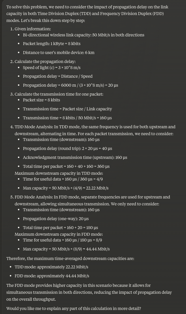
Time-Division Duplex (TDD):
- TDD uses a single frequency band but divides the time into slots.
- Communication alternates between upstream and downstream in different time slots.
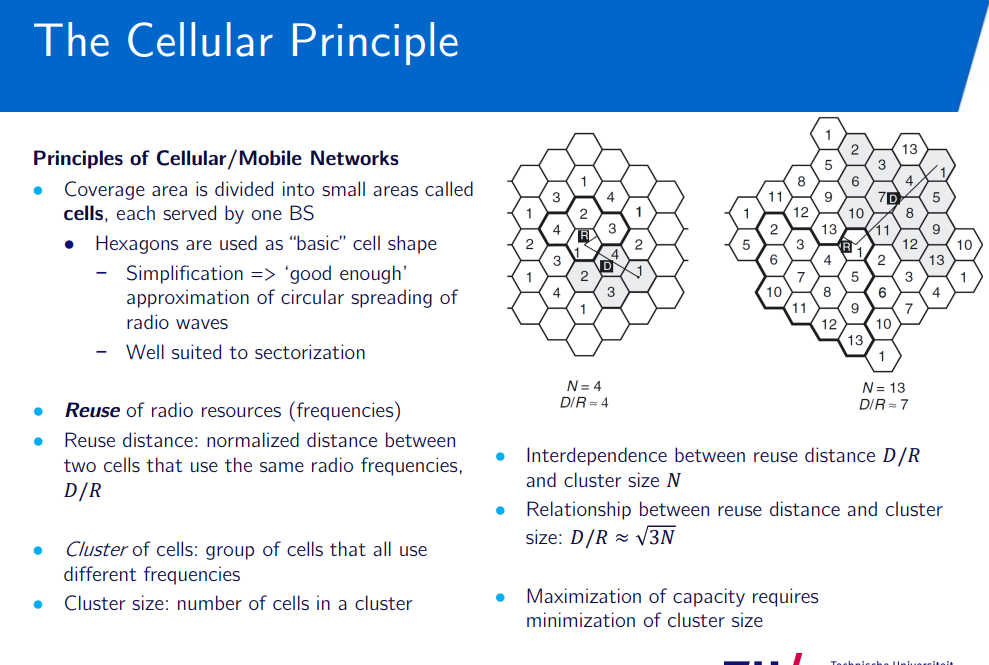
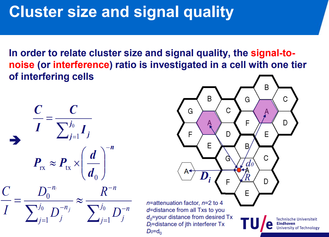
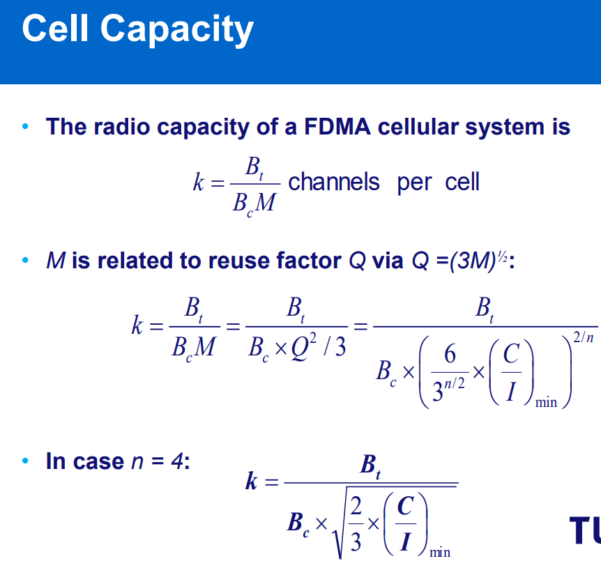
cellular concept: divide coverage areas into many subareas
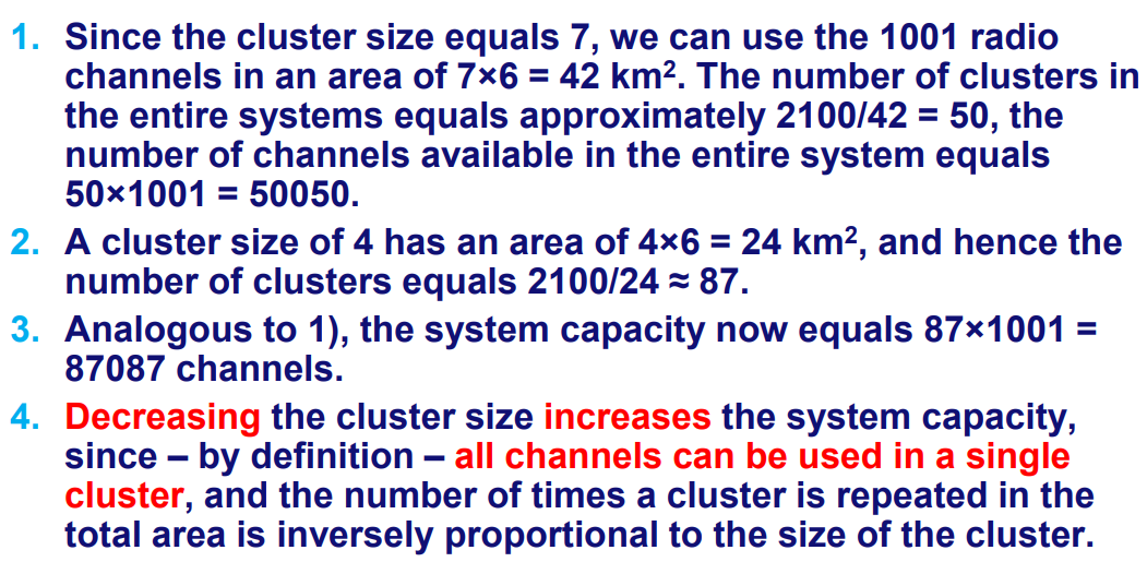
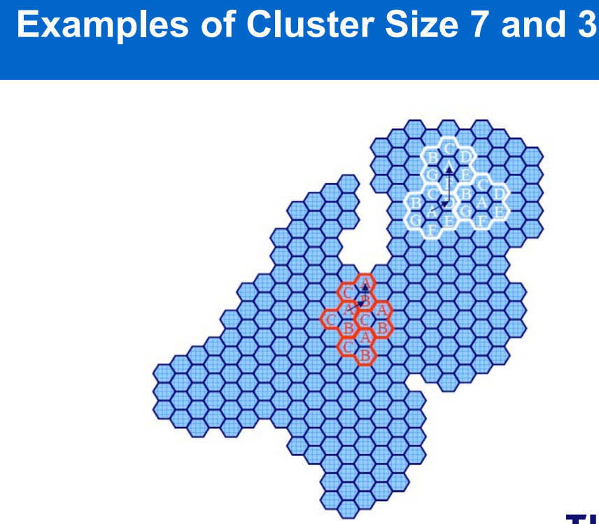
decreasing cluster size increases system capacity.
num of times cluster repeated in area inversely proportional to size of cluster.
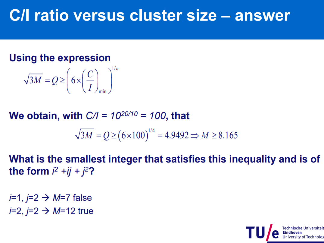
clust size = 7
channels = 1001
area =
clusters in system =
channels in system =
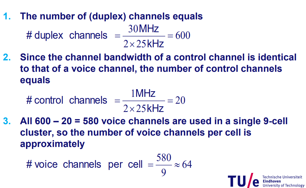
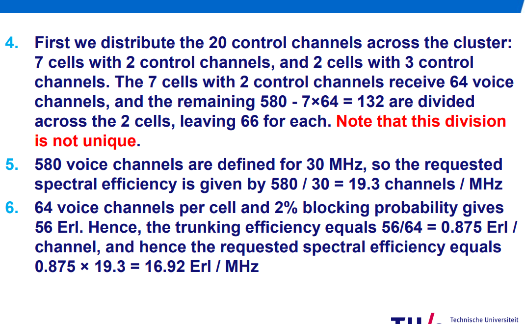
Hexagonal cell network formula:
Cluster size and channels per cell:
Co-channel reuse ratio (Q):
TDMA
Passive optical network - Wikipedia
Carrier-sense multiple access - Wikipedia
Time-division multiple access - Wikipedia
Shares single carrier frequency with multiple users
Less power control than CDMA, but more flexible than FDMA
Time-division multiple access (TDMA) is a channel access method for shared-medium networks. It allows several users to share the same frequency channel by dividing the signal into different time slots. The users transmit in rapid succession, one after the other, each using its own time slot.
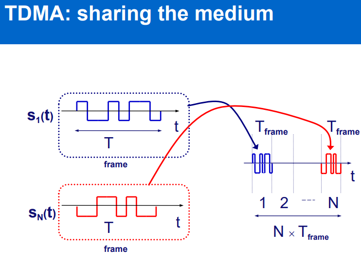
required Time Division Duplex TDD.
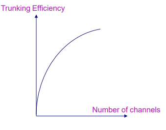
now we can calculate trunking efficiency
CDMA
Difference between FDMA and CDMA - GeeksforGeeks
Code-division multiple access - Wikipedia
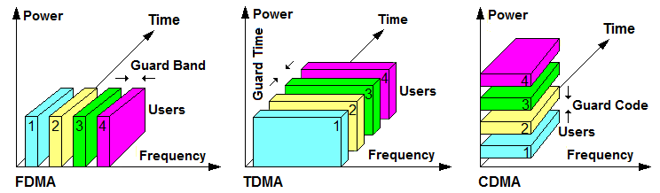
allows several users to share a band of frequencies.
it uses spread spectrum mentioned before. Using spread spectrum or spectrum hopping
faster hopping → less probability jammer would interact with your frequency
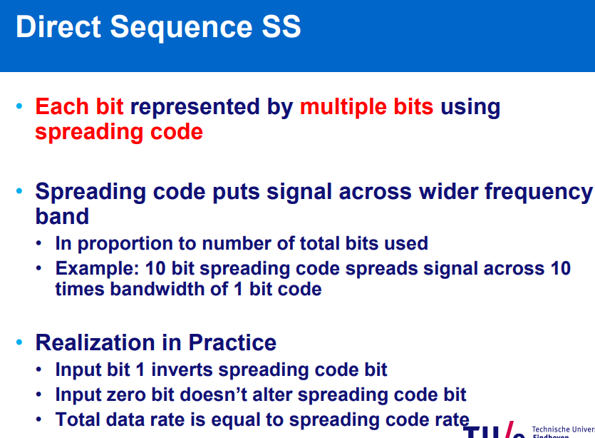
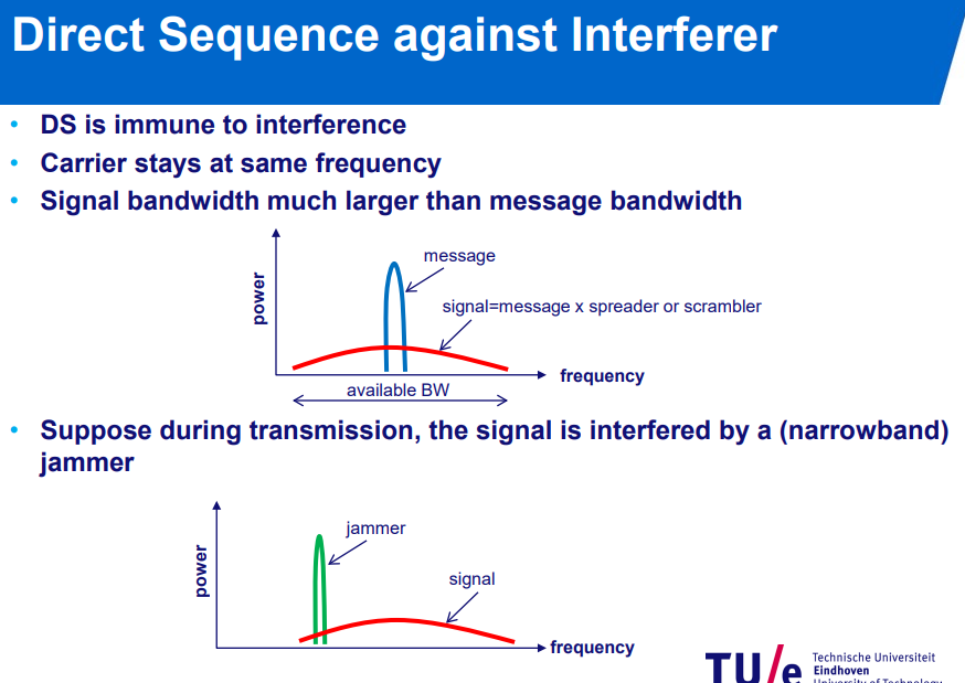
and vice versa if the jammer is spread
interference power of jamming signal reduced with processing gain:
where power per chip:
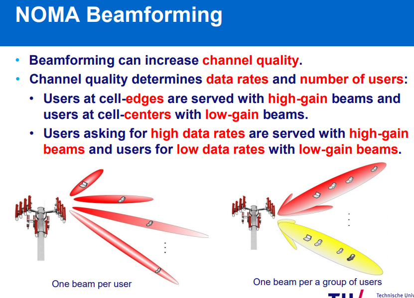
NOMA
coordinated multiuser access method that transmits different data streams over the same radio resources and employs detection algorithms such as SIC to decode the multiplexed data streams at the receiver.
SIC: allows decoding of two or more packets that arrived simultaneously
Non Orthogonal Multiple Access
uses power domain to separate signals.
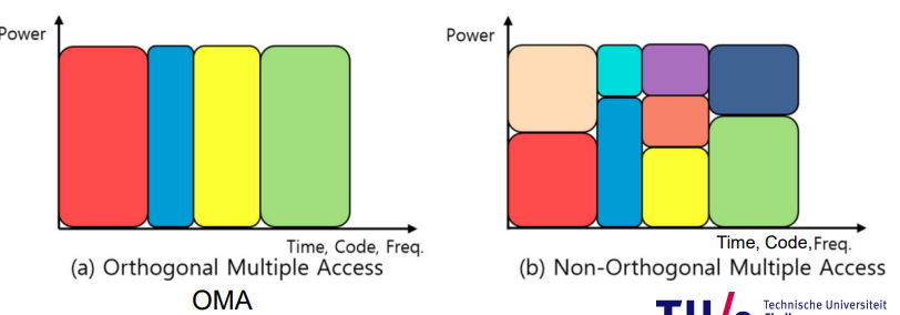
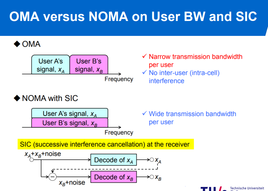
- users with better channel conditions, like a closer channel are allocated less power…
- Successive interference cancellation (SIC) is used at receivers.
Wired Networks
Peer-to-peer - Wikipedia
Point-to-multipoint communication - Wikipedia
Network topology - Wikipedia
Digital subscriber line - Wikipedia
DOCSIS - Wikipedia
- Channel bonding combines multiple network connections into a single, high-speed “superhighway” for your data.
- Optical code division multiple access (OCDMA) is a type of multiplexing technology that is utilized in optical communication systems. It enables the simultaneous transmission of several signals over a single optical fiber, with each signal being identified by a distinct code.
Wavelength-division multiplexing (fiber optic)(WDM) - Wikipedia
- capacity upgrade
- different transmission formats
- scalability
- wavelength routing/switching
- Wavelength spacing practically depends on
- modulation bandwidth
- optical filter bandwidth
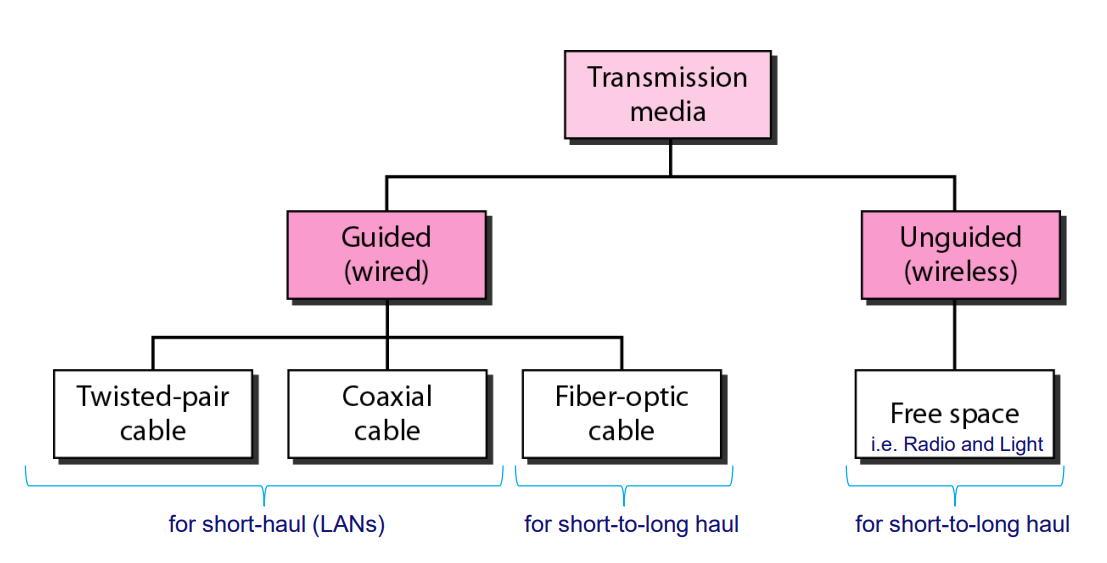
Transmission Media
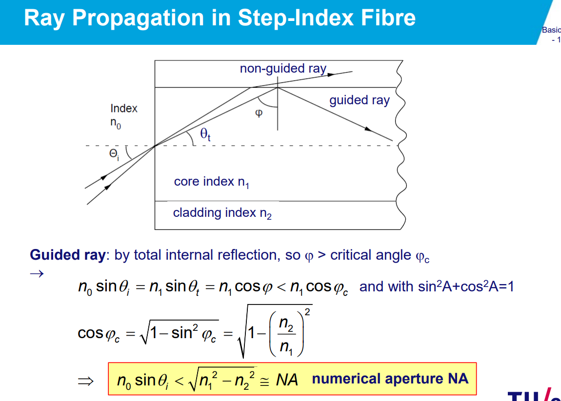
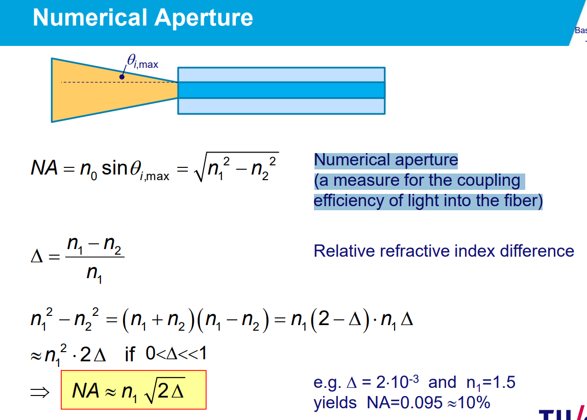
Numerical aperture - Wikipedia
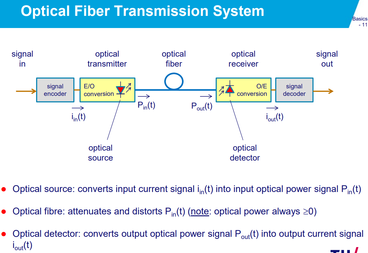
attenuation: signal get smaller.
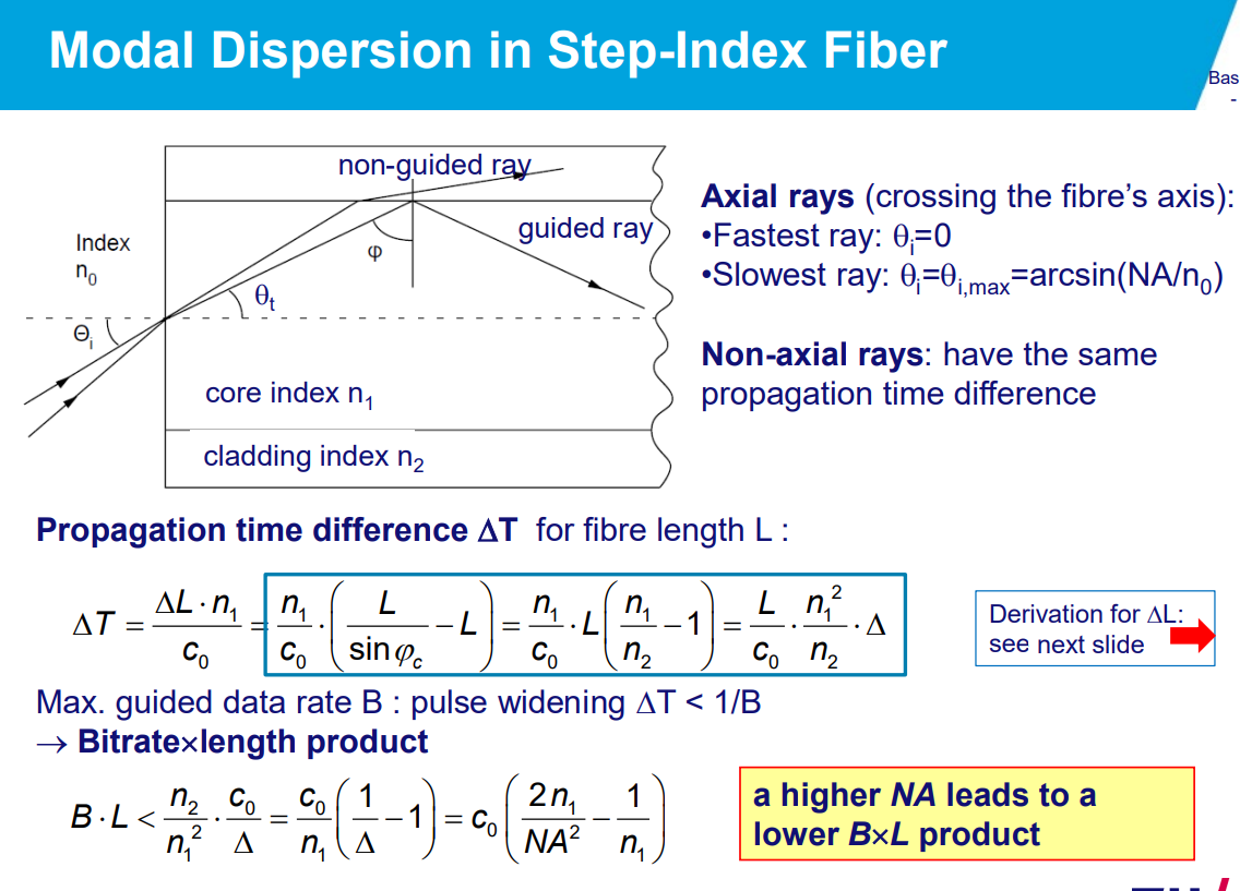
dispersion: signals get mis-shaped.
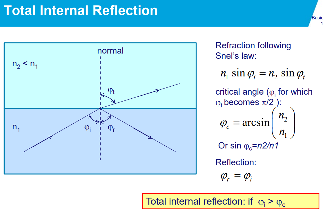
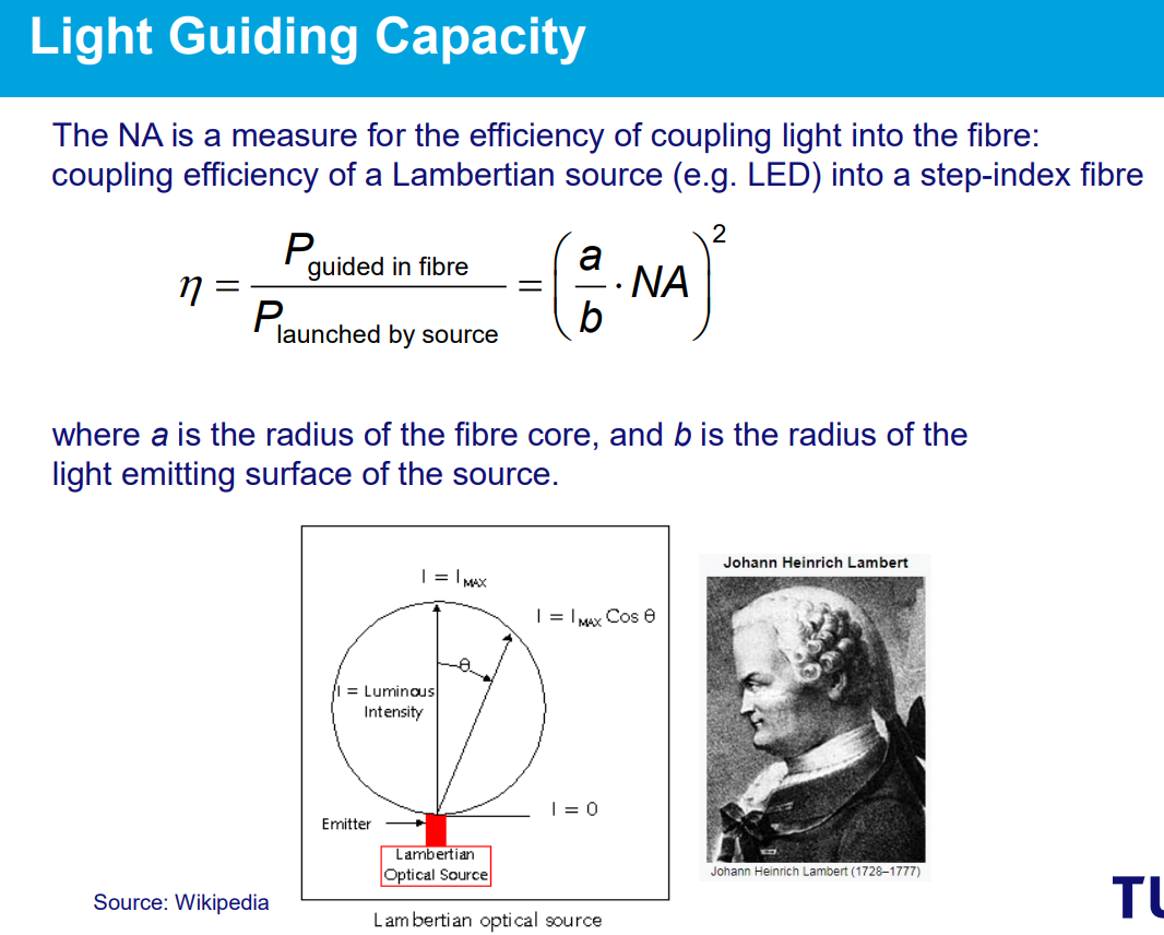
Numerical aperture (a measure for the coupling efficiency of light into the fiber).
numerical aperture (NA) of an optical system is a dimensionless number that characterizes the range of angles over which the system can accept or emit light.
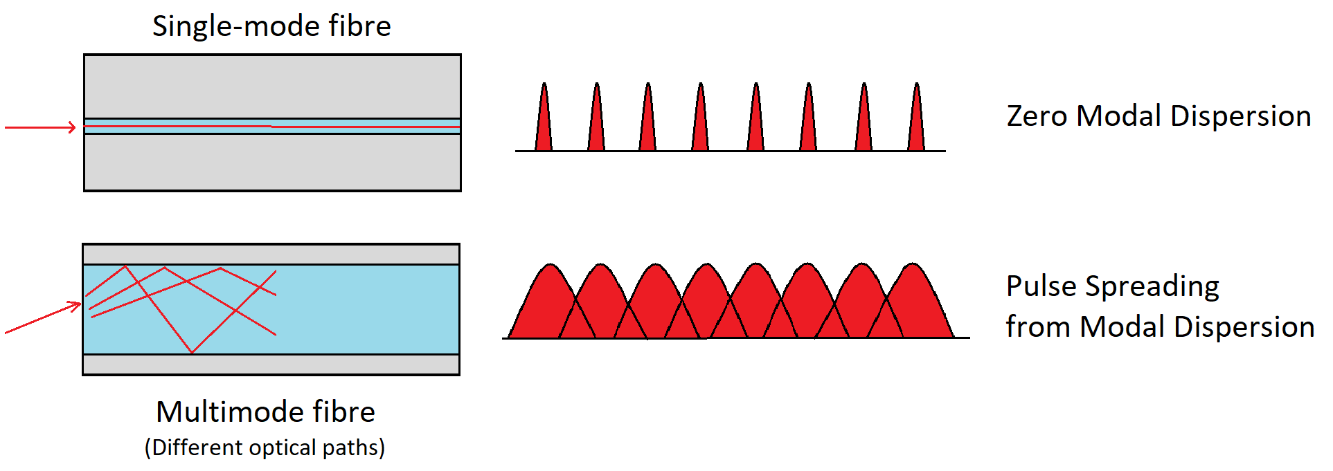
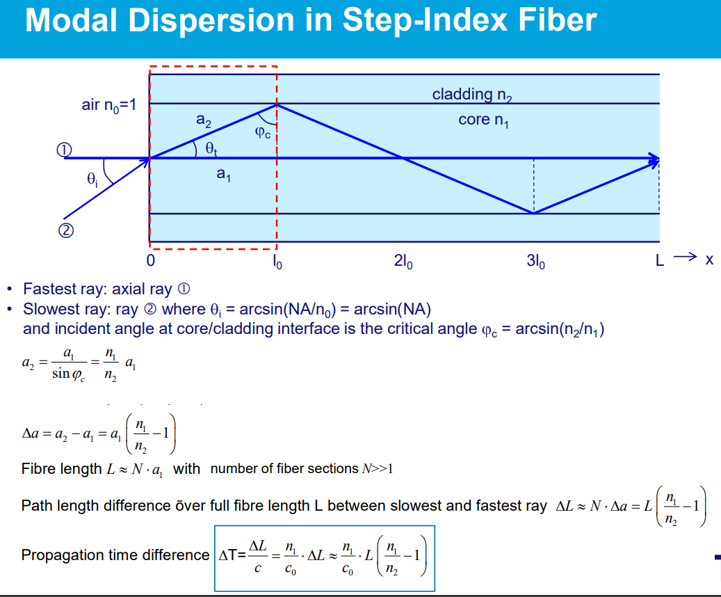
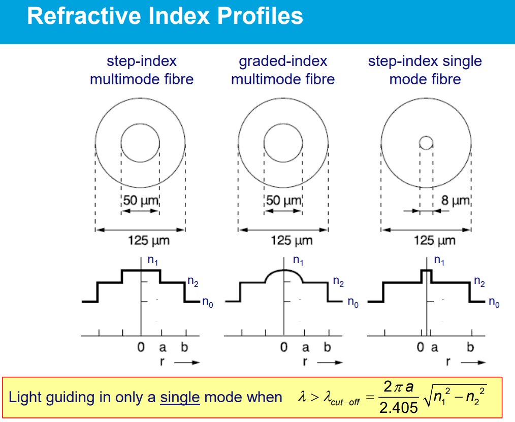
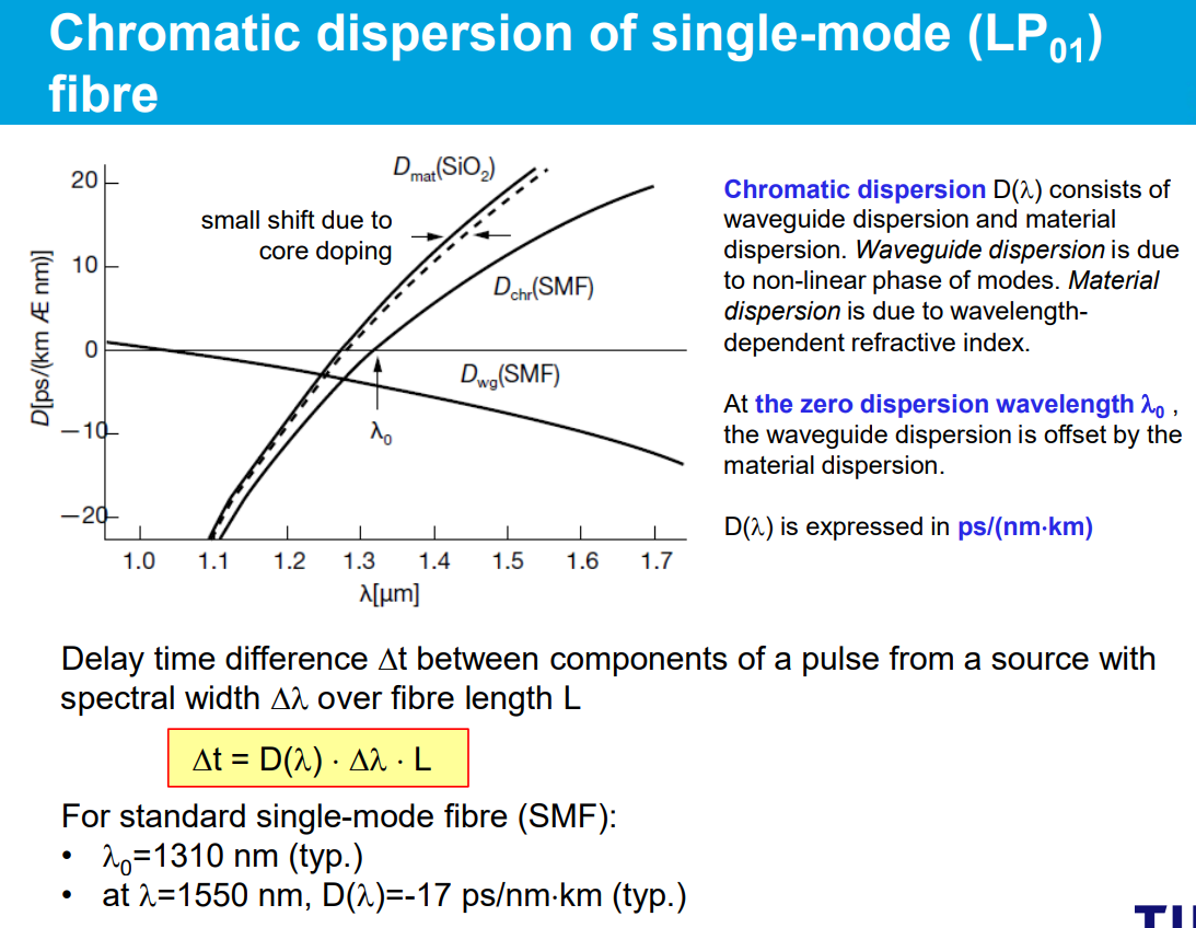
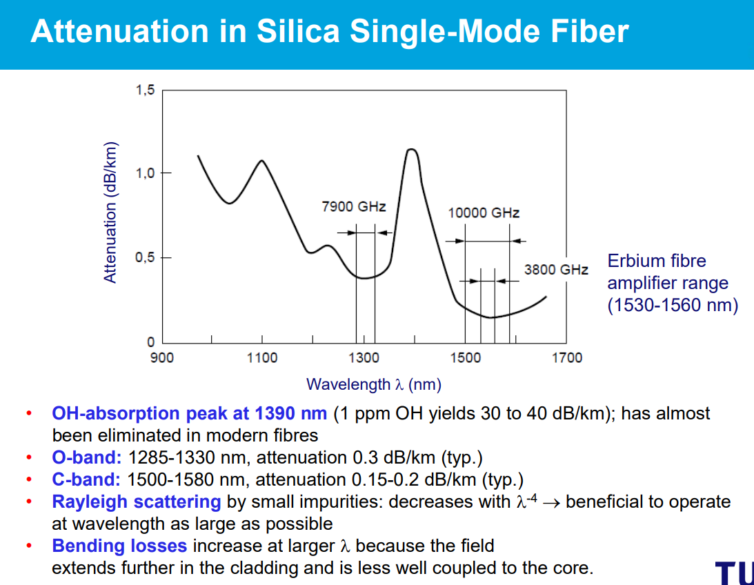
- Polymer is ductile → POF easier to handle than silica fibre
- Large core diameter → eases fibre coupling; small dust particles and scratches on fibre end face have less impact.
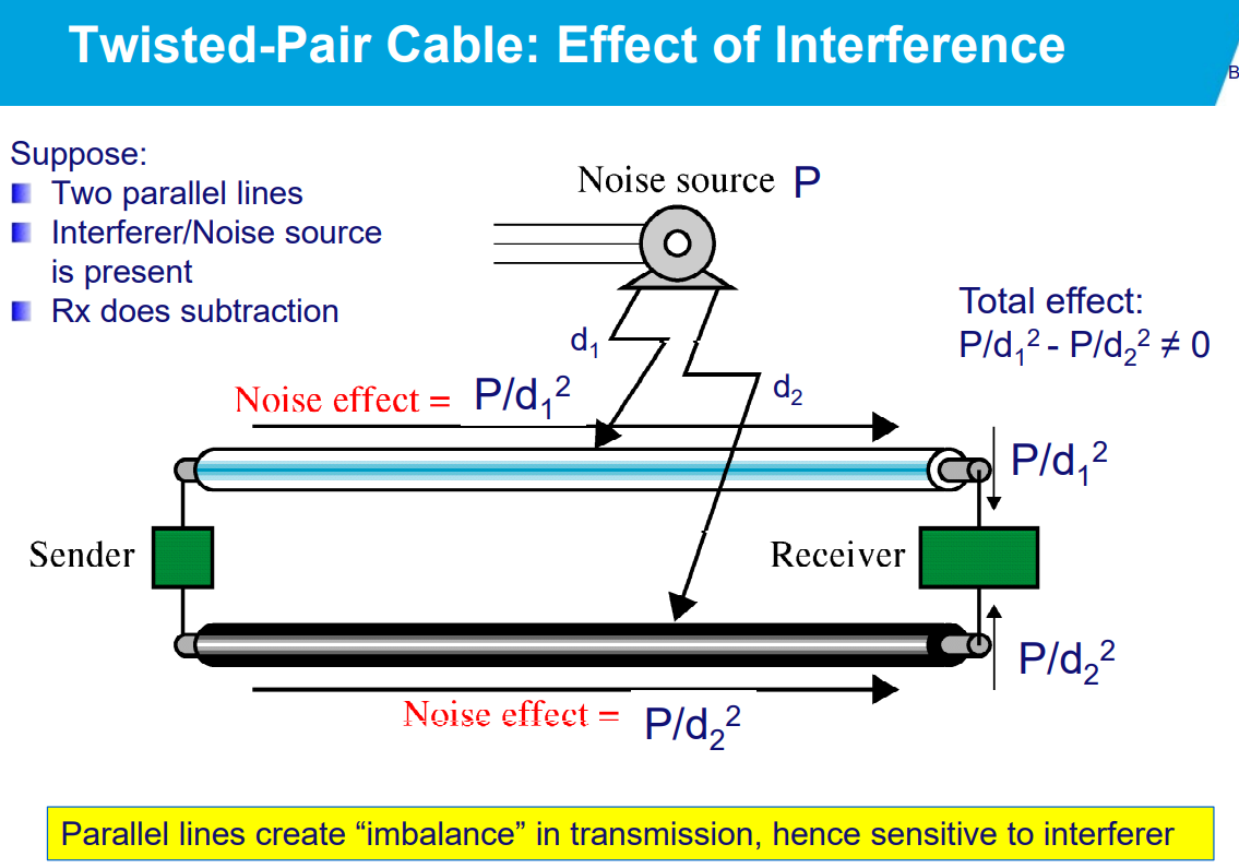
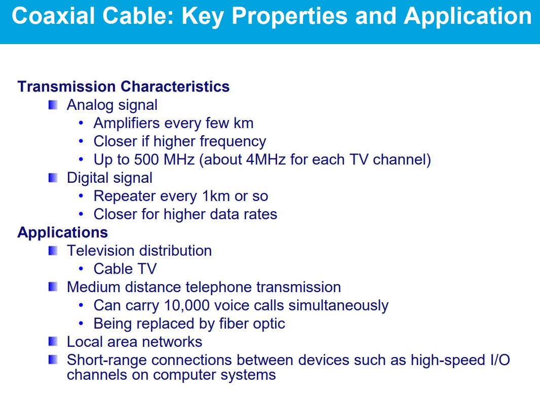
Graded-index multimode fibers have a core in which the refractive index gradually decreases from the center towards the cladding. This design reduces modal dispersion compared to step-index multimode fibers, where the refractive index changes abruptly at the core-cladding boundary. The advantages are:
- Reduced Modal Dispersion: The gradual change in refractive index helps to equalize the travel times of different light modes, reducing modal dispersion and allowing higher bandwidth over longer distances.
- Higher Bandwidth: Because of reduced modal dispersion, graded-index fibers can support higher data rates compared to step-index fibers.
- Improved Signal Quality: The reduction in dispersion leads to a cleaner signal with less inter-symbol interference, improving overall data integrity and reducing error rates.
Optical Networking
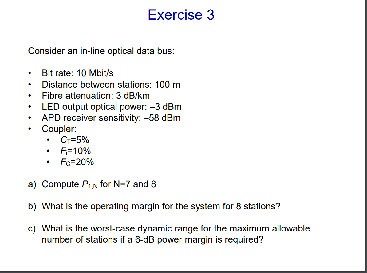
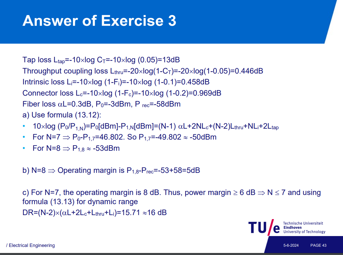
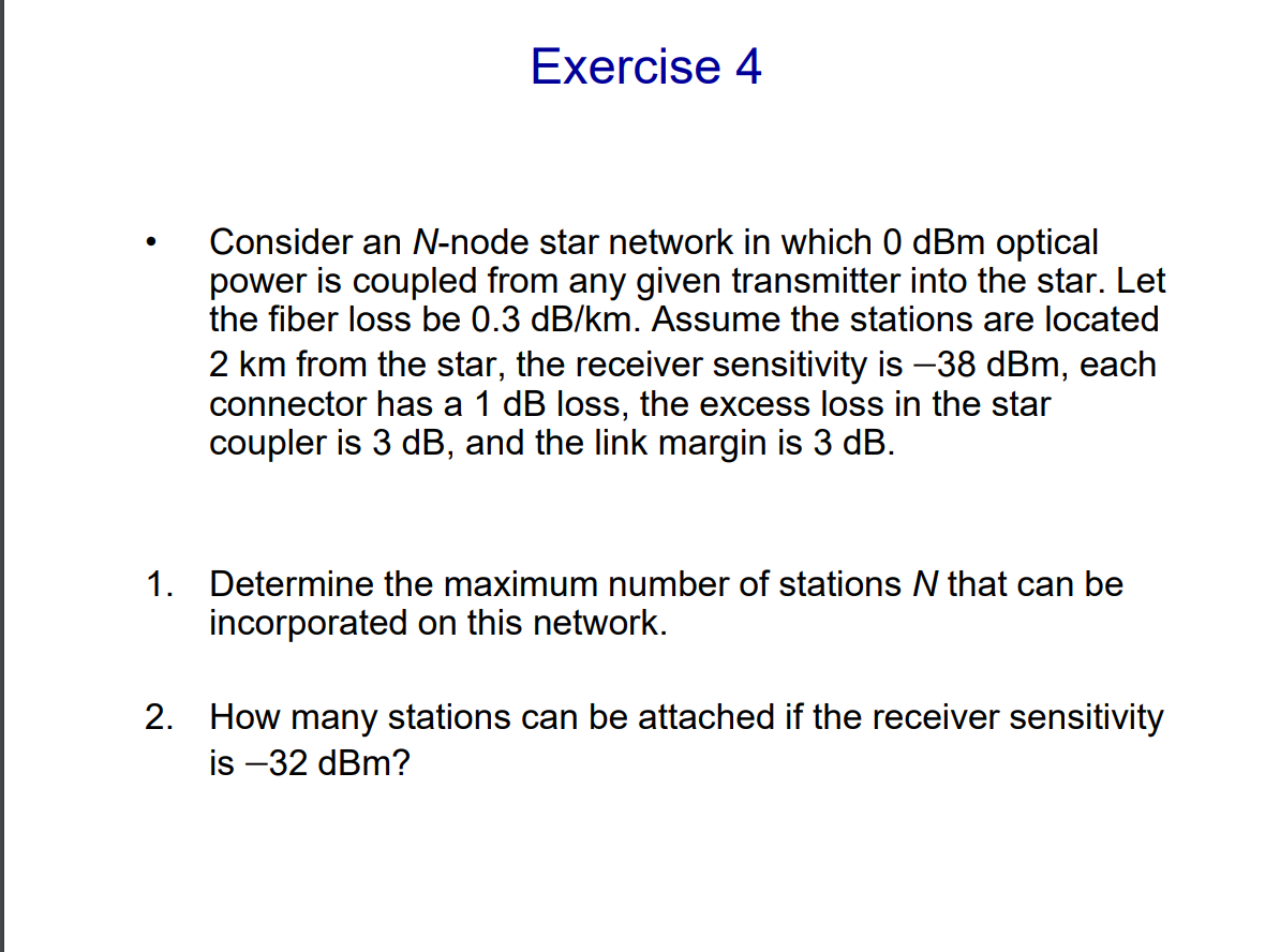
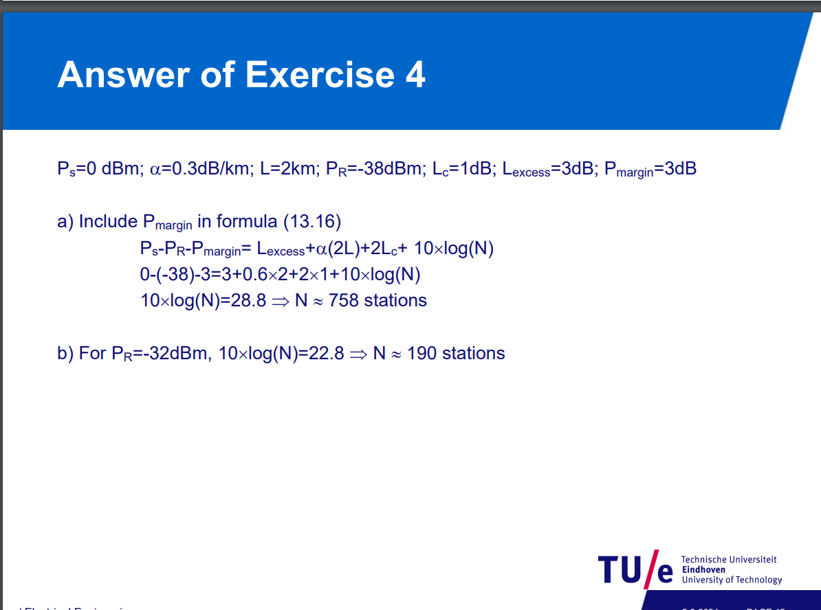
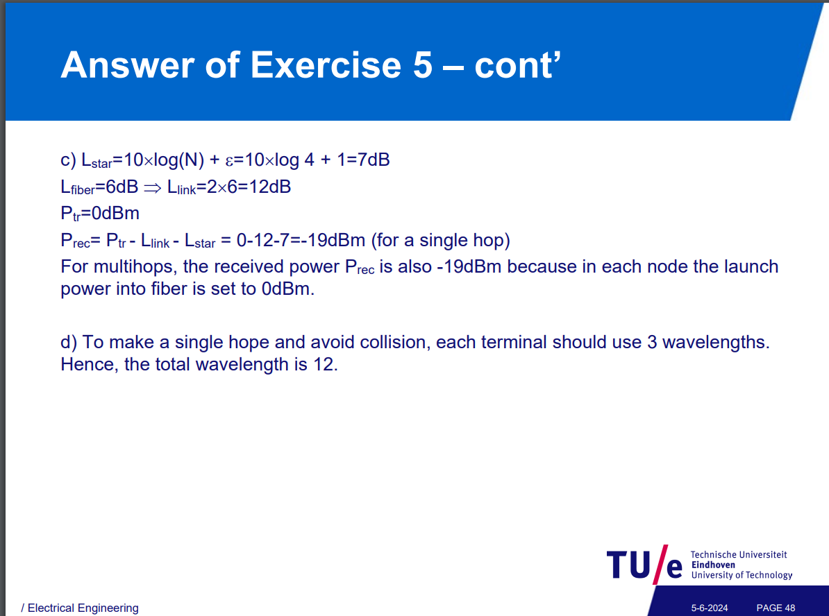
For a star coupler with N outputs, the power loss due to splitting is: Loss (dB)=
Thus, the loss introduced by the star coupler increases logarithmically with the number of rooms connected.
Total allowable loss = Transmitter power - Receiver sensitivity - Link margin
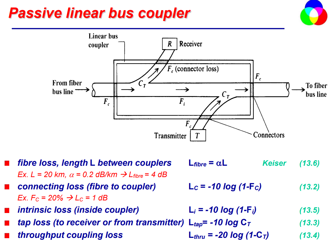
bus, ring, star, mesh network topologies…
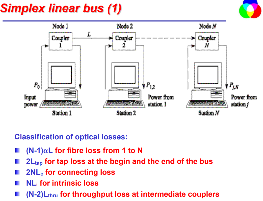
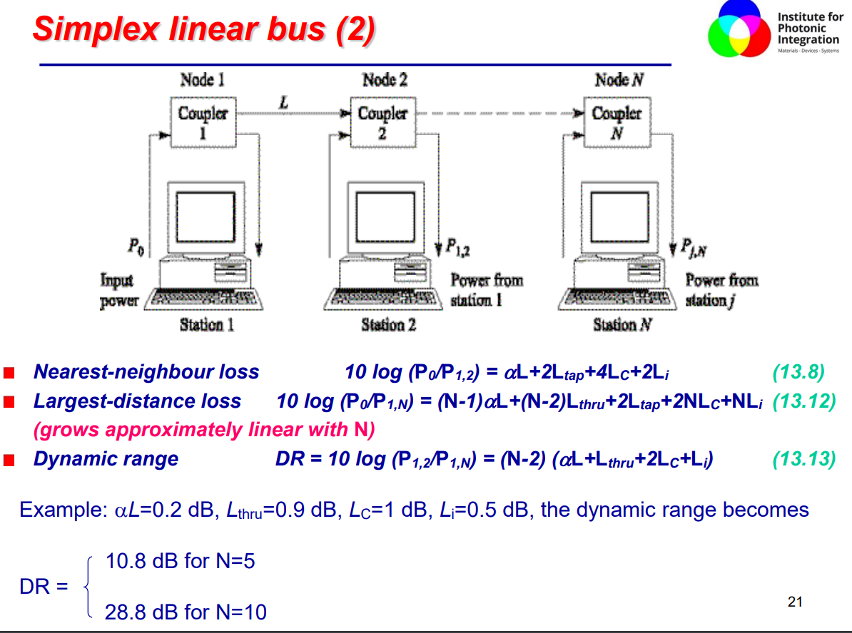
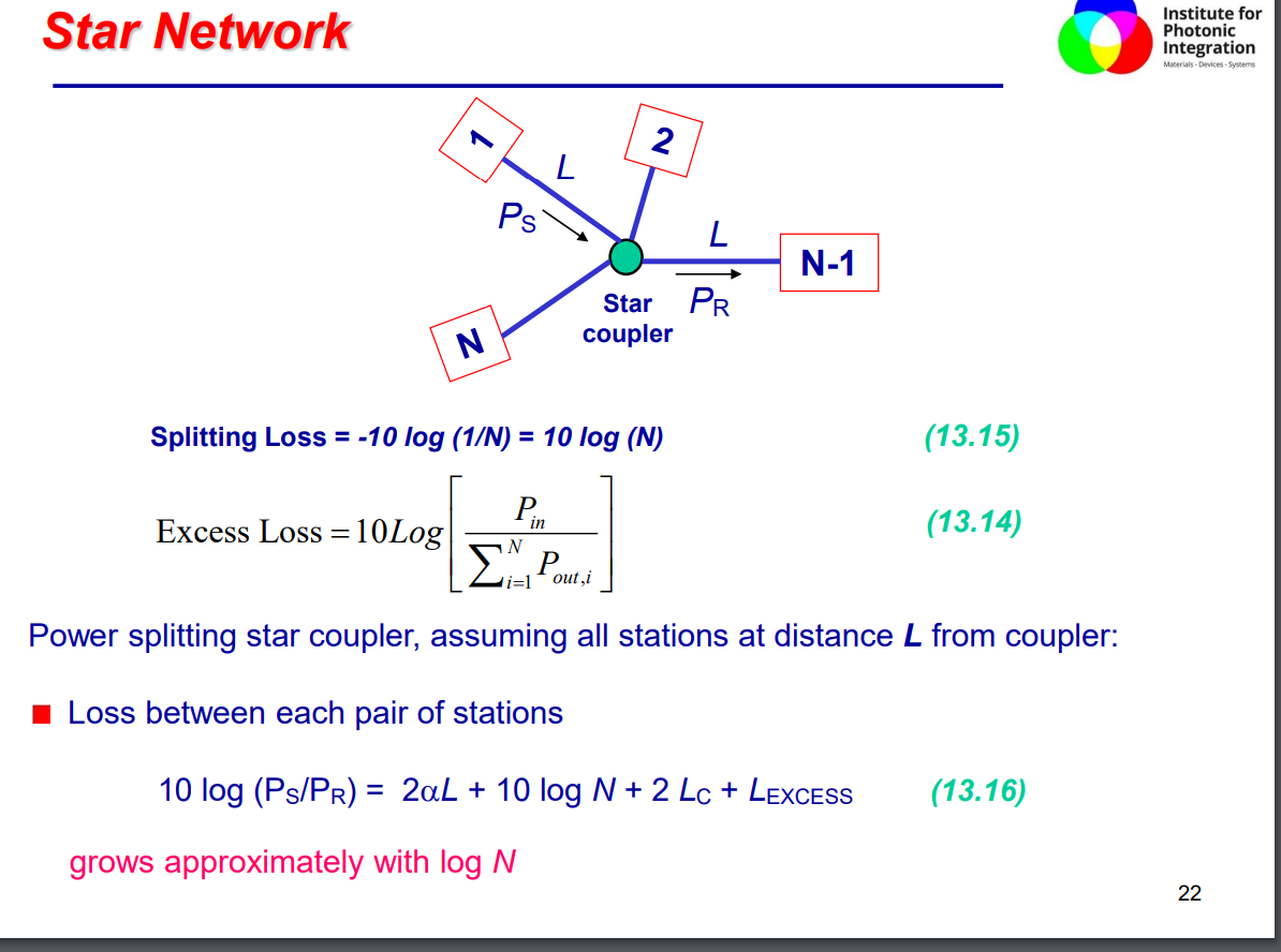
-
star topology is more power efficient, while linear grows linearly, star network levels off.
-
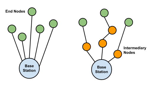
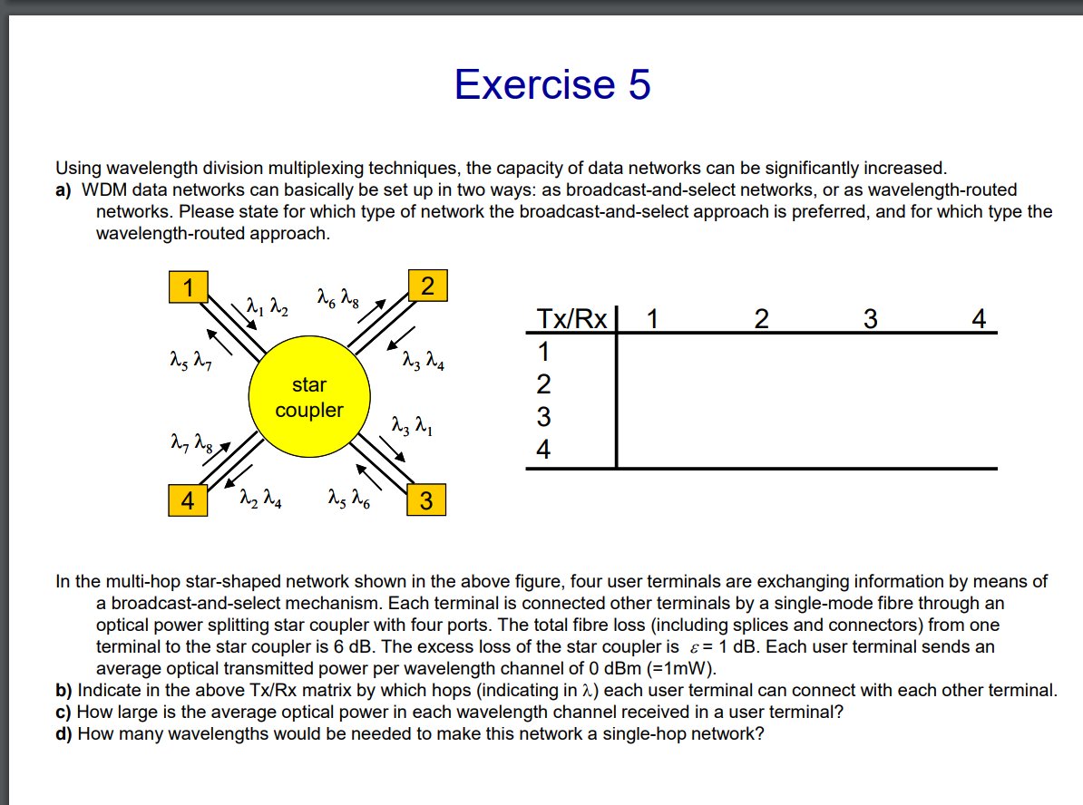
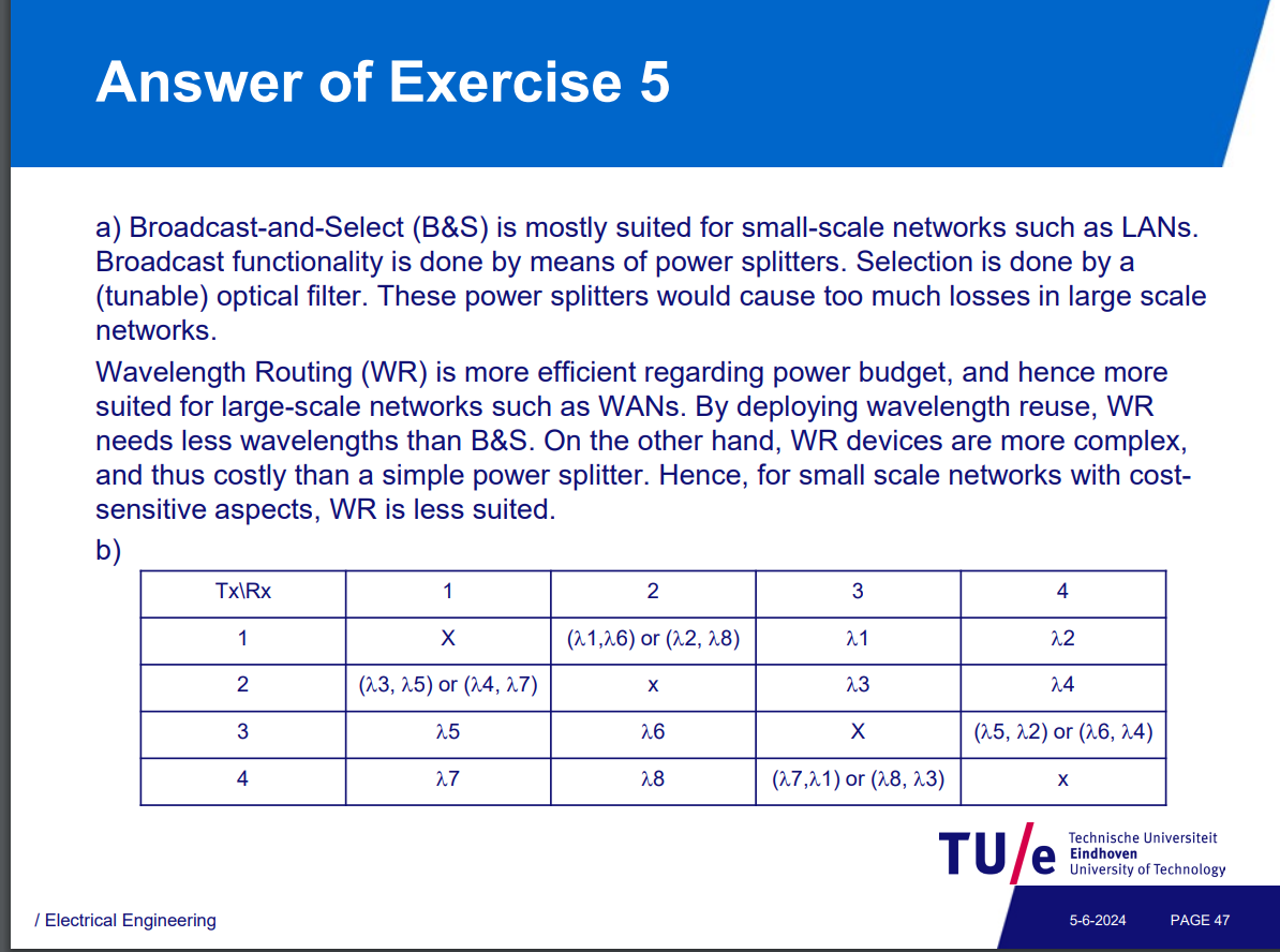
Single hop broadcast-and-select.
-
Multi-hop broadcast-and-select.
-
Single-Hop vs. Multi-Hop Networks | Advanced PCB Design Blog | Cadence
-
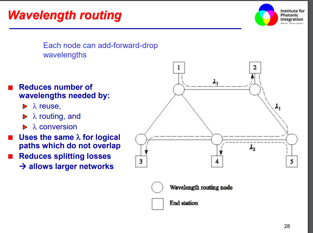
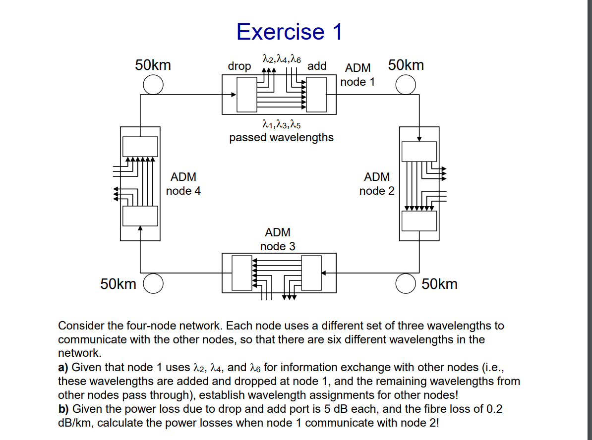
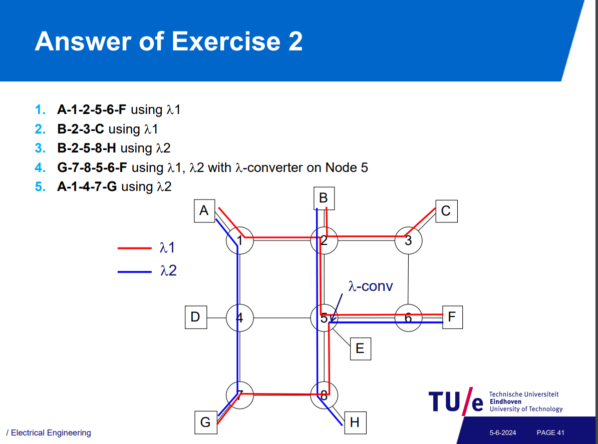
A scalable optical network can be constructed by taking several WDM links and connecting them at a node by a switching subsystem. Using such nodes (also called wavelength routers) interconnected by fibers.
-
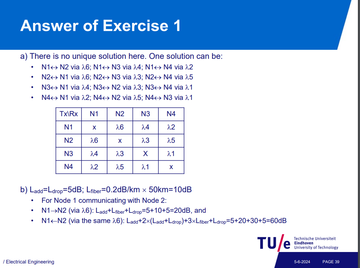
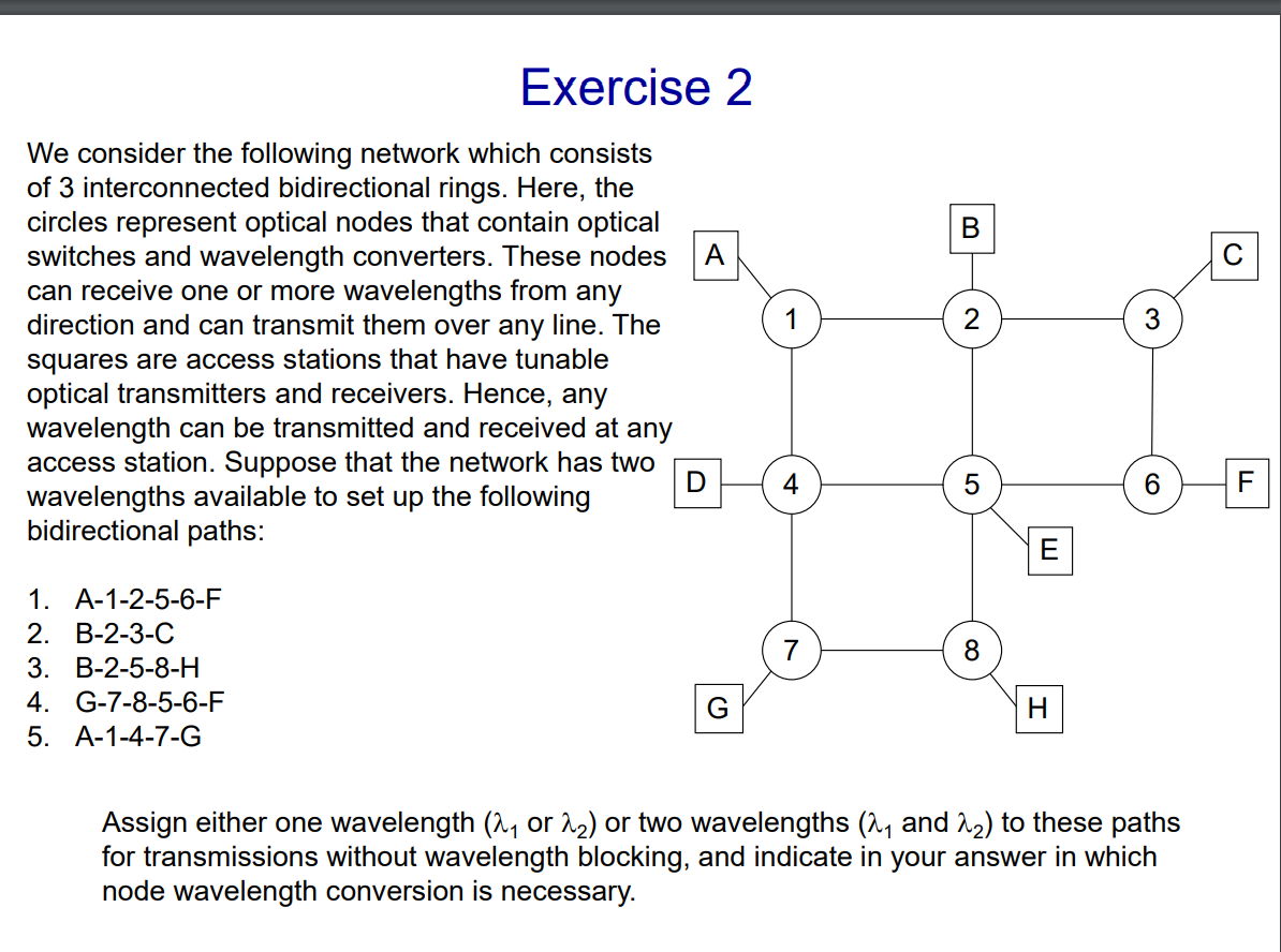
Avoiding λ-collision by λ-conversion
Passive Optical Networks
Passive optical network - Wikipedia
fiber-optic telecommunications network that uses only unpowered devices to carry signals, as opposed to electronic equipment. In practice, PONs are typically used for the last mile between Internet service providers and their customers.
Internetworking and Transport Reliability (Georgios)
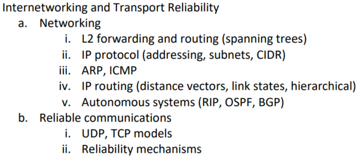
Border Gateway Protocol - Wikipedia
Autonomous system (Internet) - Wikipedia
Internet Control Message Protocol - Wikipedia
Hierarchical routing - Wikipedia
Reliability (computer networking) - Wikipedia
Networking
Topic: Networks and Error Control
Difference between Hub, Switch and Router - GeeksforGeeks
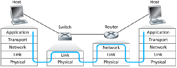
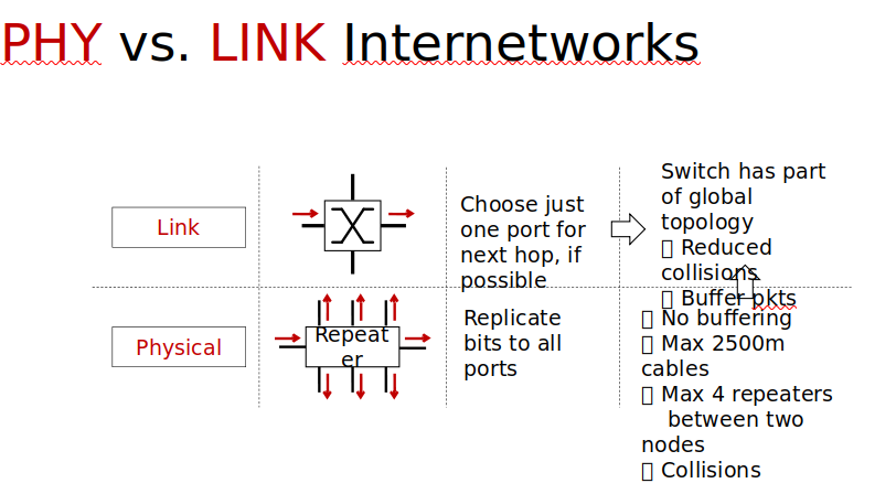
Hub: A L1 physical device which forwards all signals to all connected devices.
Swicth: A L2 data device which can determine to whom the data needs to be sent. (MAC)
Router: A L3 network device uses a routing table, several paths for a source.(IP)
0.0.0.0/0 default route to internet
OSI model
IP is L3 while MAC is L2
OSI Model - Text
OSI Explained - Video
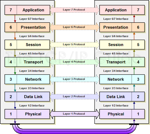
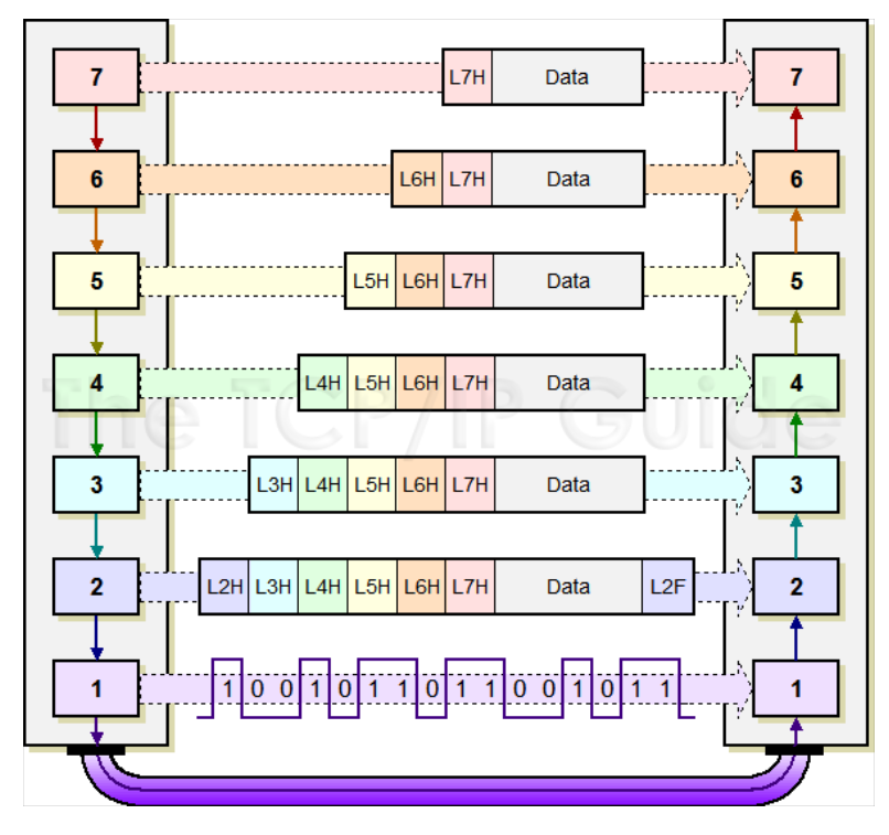
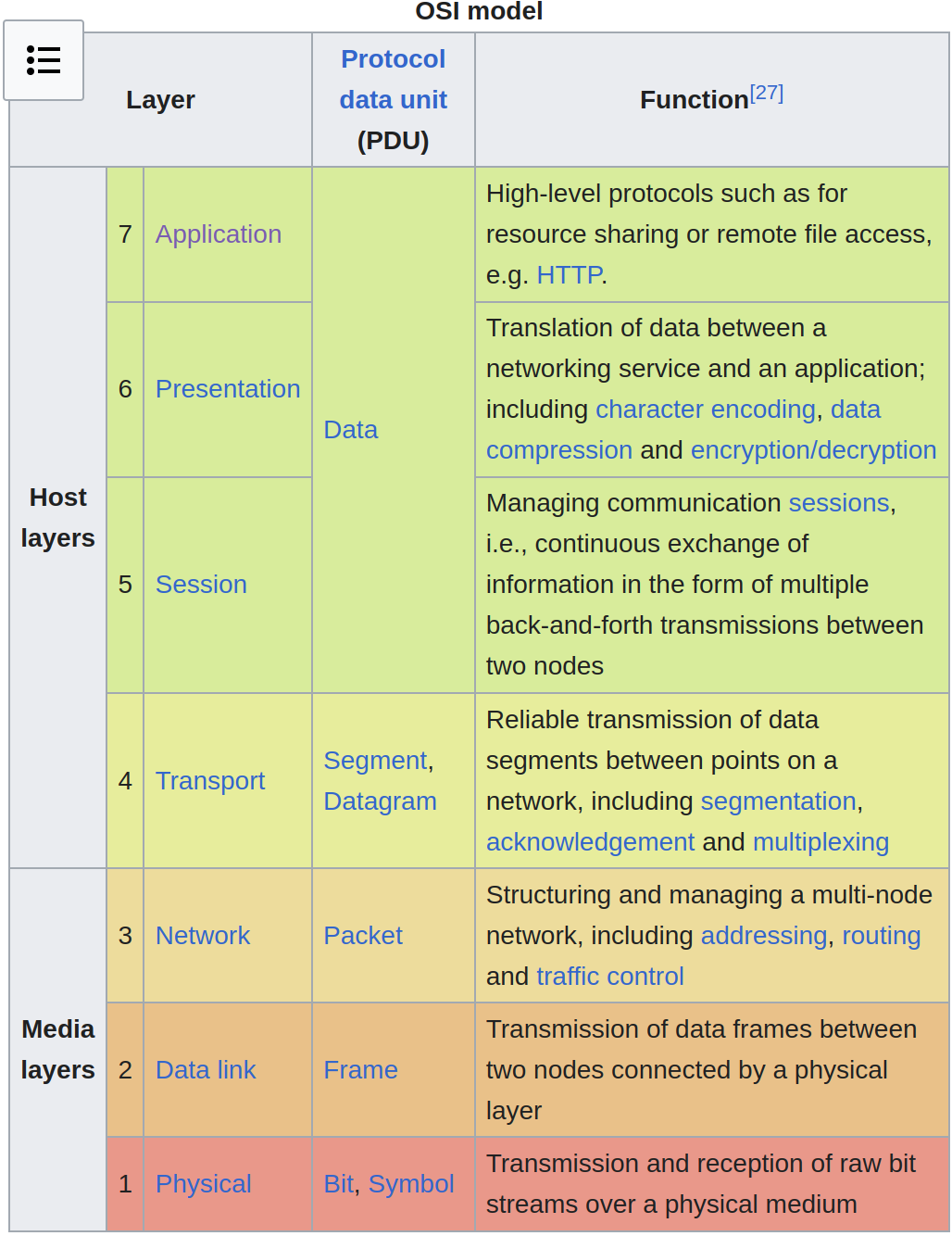
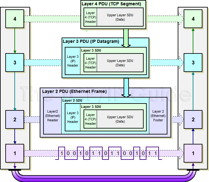
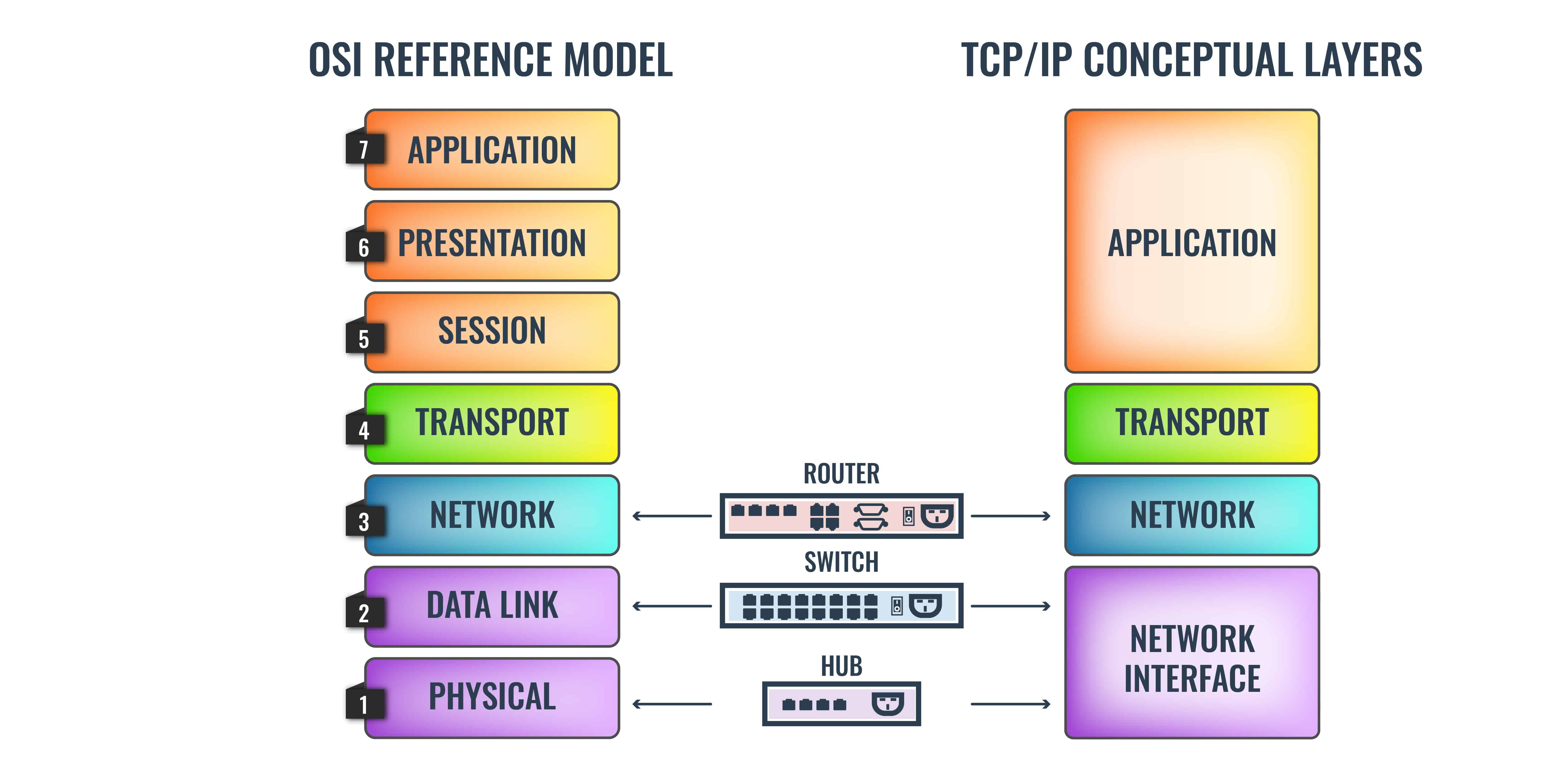
APSTNDP (All People Seem To Need Data Processing)
- Application: Protocols network apps use (HTTP,FTP)(host communication).
- Presentation: Data modulation.
- Session: Manage connection (API).
- Transport: Data flow control (TCP(slower,feedback)/UDP).
- Network: Routers communication (IP(packet)/ROUTING/Pathing).
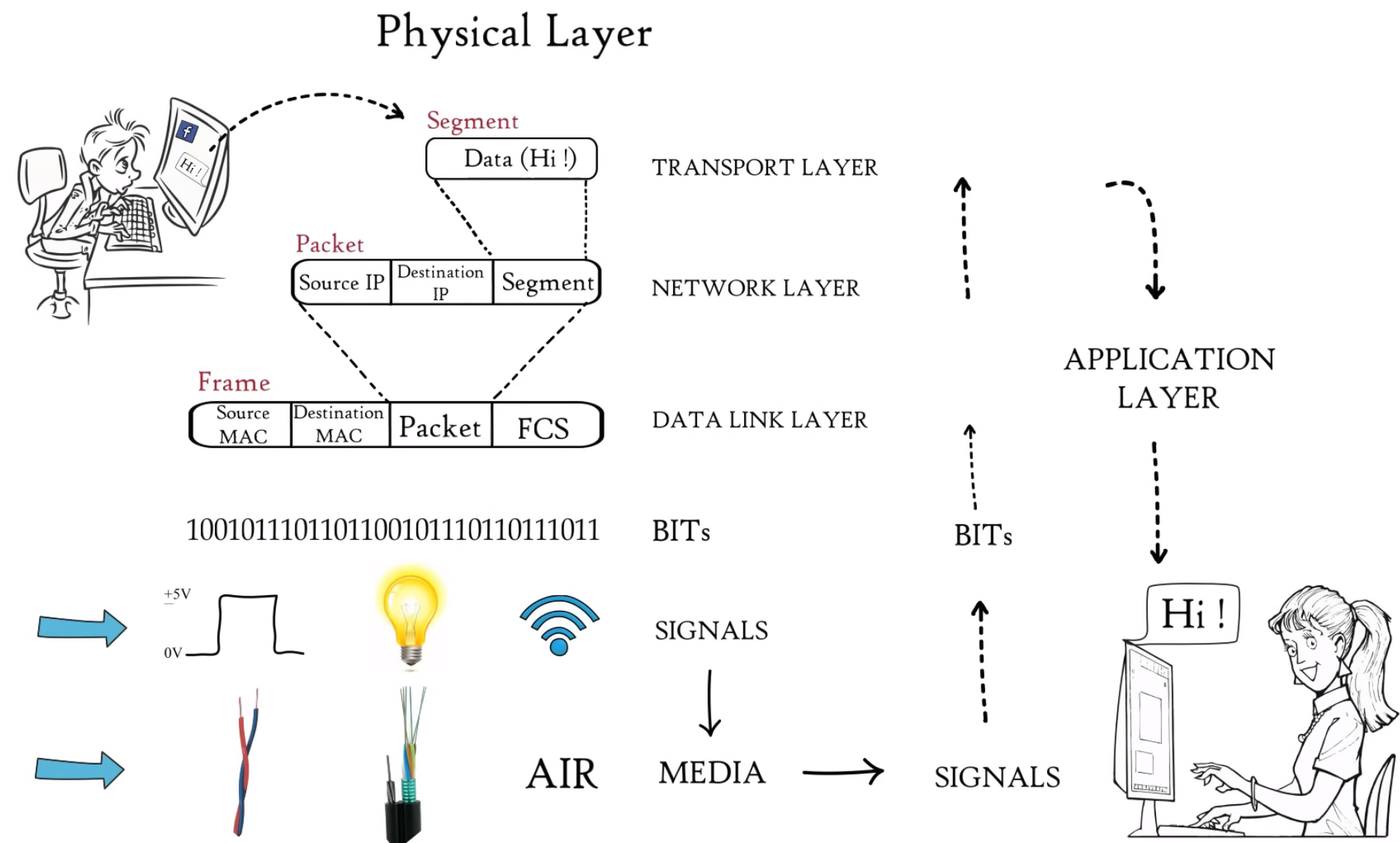
- logical addressing: data packet (ip1,ip2/segment).
- Data Link: Access media, access control.
- physical addressing: frame (mac1/mac2/ip1,ip2/segment/tail).
- Physical: Bits to Physical signal and Transfer.
User Datagram Protocol - Wikipedia
Transmission Control Protocol - Wikipedia
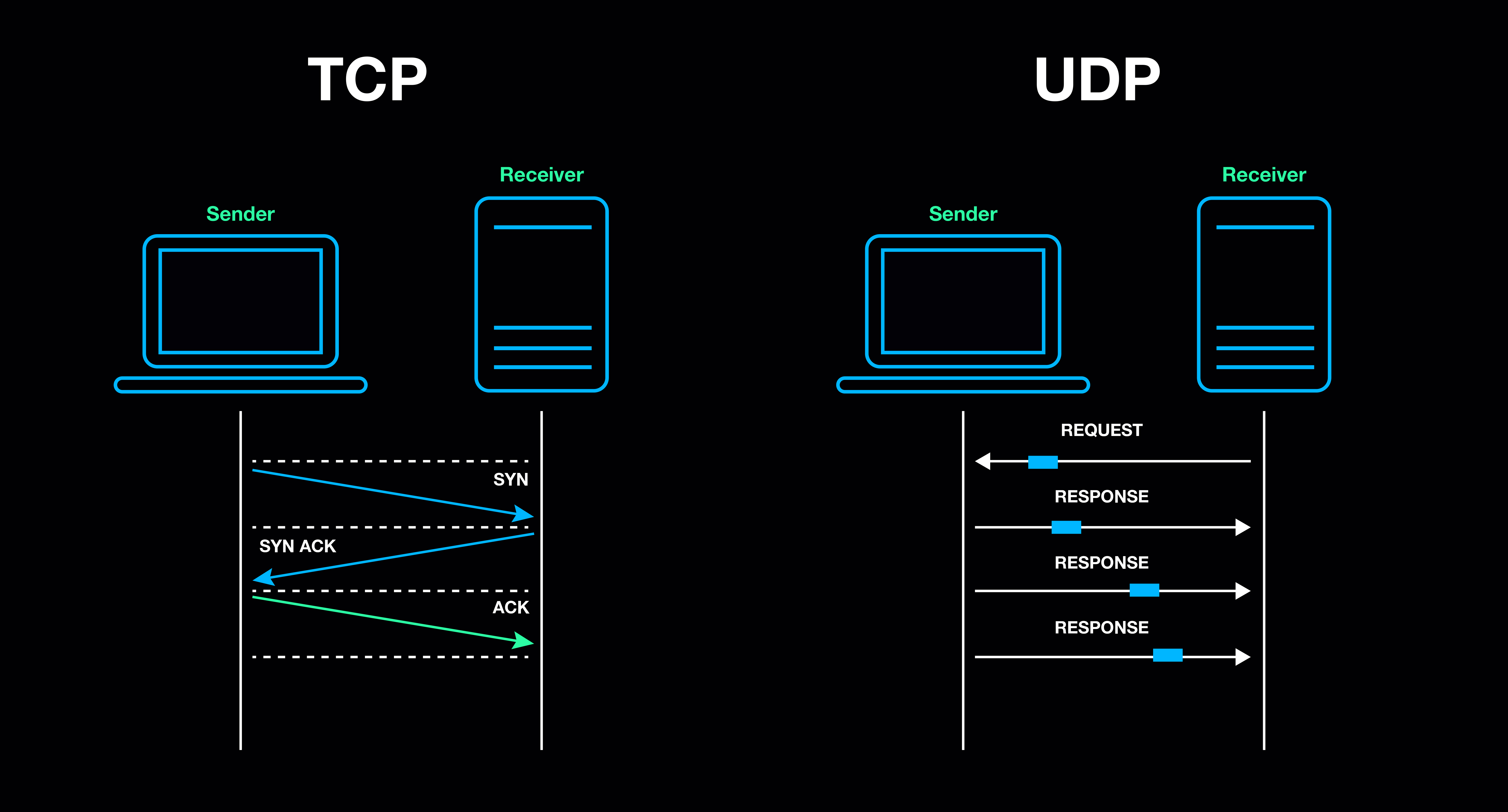
- UDP being a connectionless protocol, them messages are forwarded without establishing a connection between the two communicators…
- A UDP datagram consists of a datagram header followed by a data section (the payload data for the application). The UDP datagram header consists of 4 fields, each of which is 2 bytes (16 bits)
Interconnected World, Datagram Switching, Datagram Networks
Switching Techniques in Computer Networks - YouTube
Basics of Bridge - YouTube
Datagram - Wikipedia
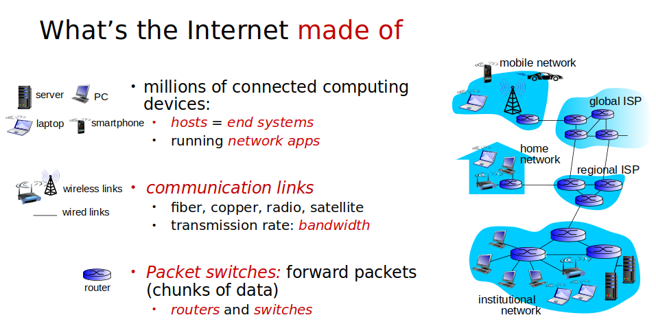
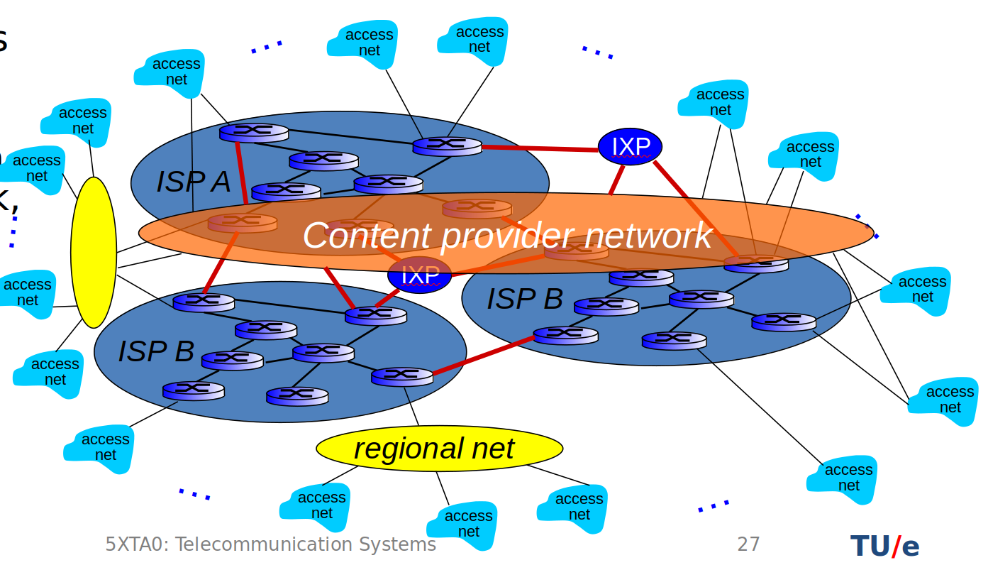
hosts connected over communication links which do packet switching and routing.
packet-switching: hosts break application-layer messages into packets. Packets go from router to router, to connect ISPs (internet service providers).
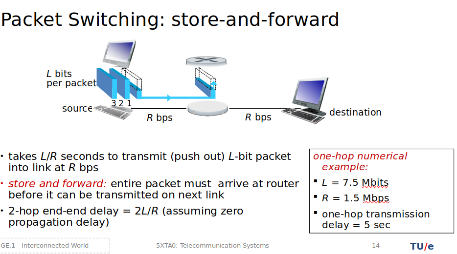
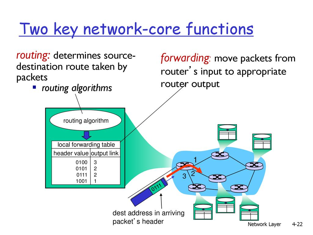
- packet switching has queueing and delays.
- Circuit switching reserves a dedicated physical path for the entire connection duration. (can be TDM or FDM based).
- It is connection-oriented; a path must be established before data transmission.
- Packet switching, a connectionless method, sends data packets independently without a dedicated path.
- ISPs communicate between IXPs (Internet exchange point)
- Regional networks may arise to connect access nets to ISPS
- content provider networks (e.g., Google, Microsoft, Akamai) may run their own network, to bring services, content close to end users.
datagram is a transfer unit associated with packet switching network
-
header and payload sections…
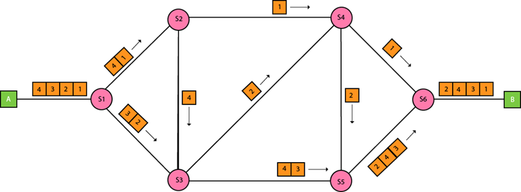
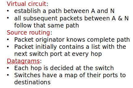
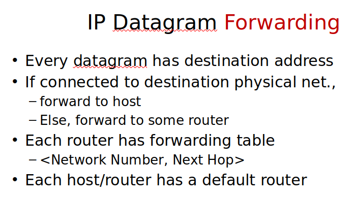
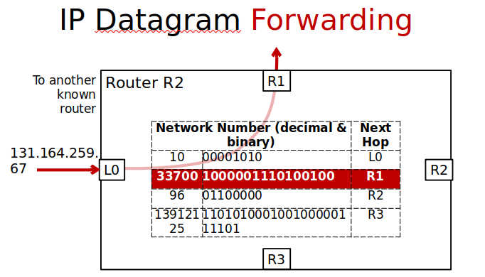
In the datagram-forwarding model of packet delivery, packet headers contain a destination address. It is up to the intervening switches or routers to look at this address and get the packet to the correct destination.
1.4: Datagram Forwarding - Engineering LibreTexts -
A datagram network is a computer network system that transmits and receives individual data packets. It has a header that defines its source and destination addresses, in addition to additional data needed to transmit the packet.
-
reordering is done by the receiver.
-
The link layer, built upon the physical layer, specifies the protocols for sending and receiving bit packets, with Ethernet being the protocol used
-
See GE.1C for bridging flow (Ethernet Briding and Bridging with Loops)
Switching Loops | Switch Networking Loop - ManageEngine OpManager
A switching loop, or bridge loop, occurs when more than one path exists between the source and destination devices.
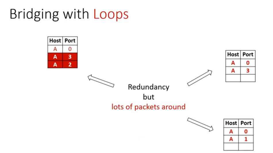
loops are not something we want to end up with as it fills the routing tables with redundancy.
Reliable communications
Topic: Networks and Error Control
Spanning Trees
Spanning Tree Protocol Explained | Step by Step - YouTube
What is Spanning Tree Protocol (STP)? - YouTube
Spanning Tree Protocol (STP) - YouTube
STP Analysis Summary
Caused due to layer 2 redundancy in the first place
Problems without STP:
- Communication loops formed
- Unstable MAC address tables
- Duplicate Frames
Solution with STP:
- Just mark one port in a switch to be ignored (ignored because we still want redundancy in case other link goes down)
- BPDU(bridge protocol date unit) probe messages to discover loops (if it receives it within 2 sec)
How to do STP:
- Elect root bridge
- Place root interfaces into forwarding state
- Each non-root switch selects its root port
- Remaining links choose a designated port
- All other ports are put in to a blocking state
Some info:
- ports(root(best to root), designated(best route to root on link), undesignated(blocking state))
- port states(disabled, blocking(traffic), listening(not forwarding, not learning), learning(mac addresses), forwarding(sending, receiving traffic))
- Lowest BID(bridge priority/mac address) → root bridge (determined after one communicated (BPDU) between all switches, since initially all bridges list themselves as root)
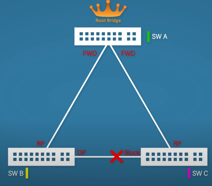
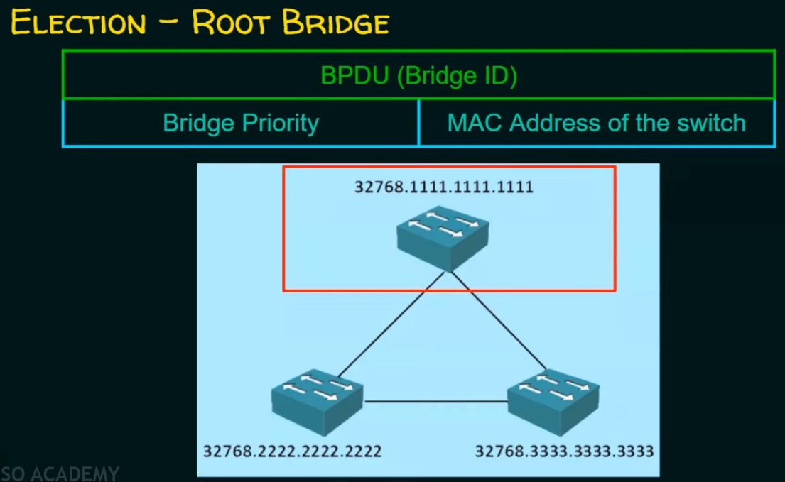
other
The need for the Spanning Tree Protocol (STP) arose because switches in local area networks (LANs) are often interconnected using redundant links to improve resilience should one connection fail. However, this connection configuration creates a switching loop resulting in broadcast radiations and MAC table instability. If redundant links are used to connect switches, then switching loops need to be avoided.
Spanning Tree Protocol - Wikipedia
Switching loop - Wikipedia
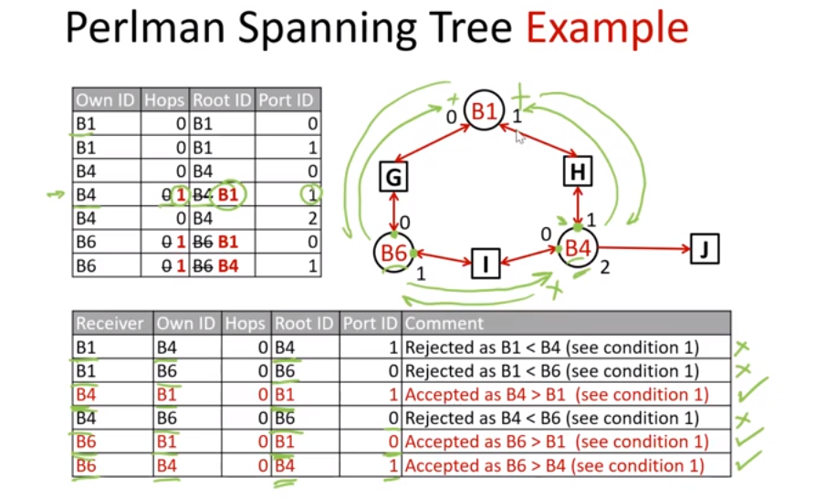
Hubs are L1, which form connection to devices, and are interconnected through bridges forming a network.
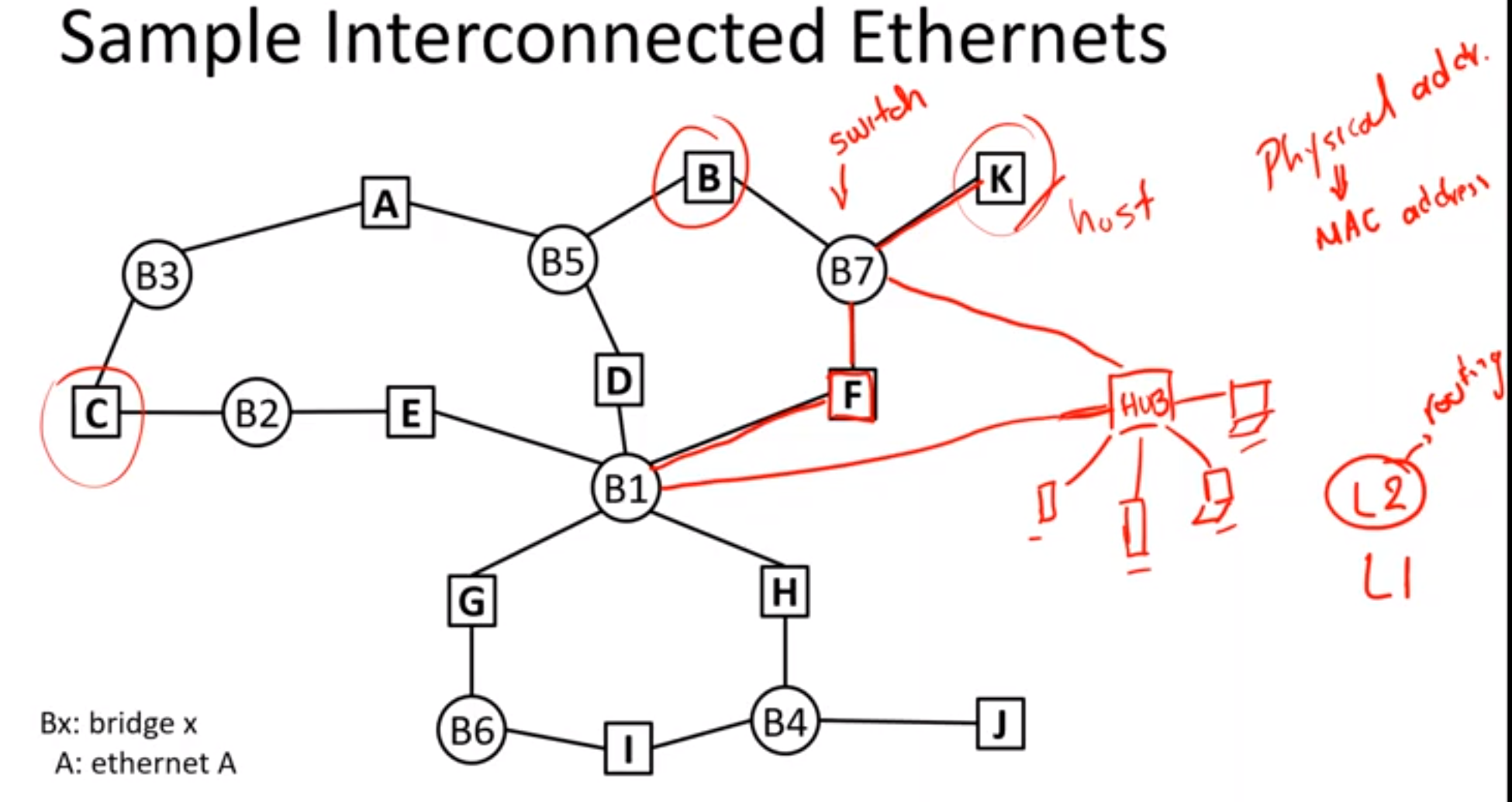
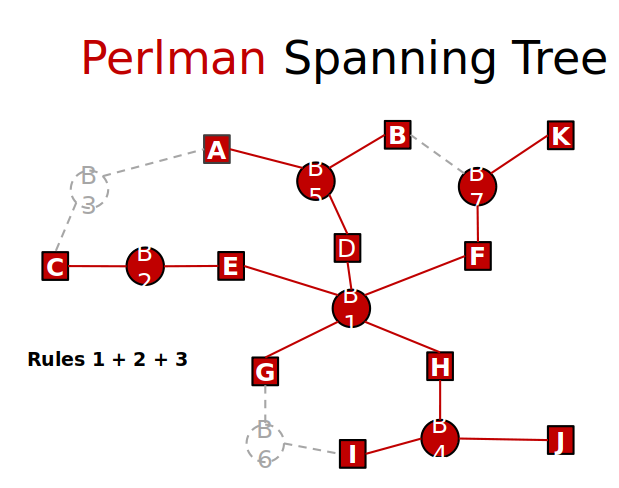
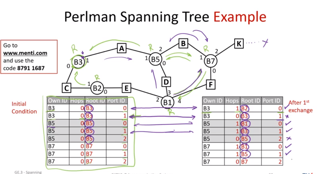
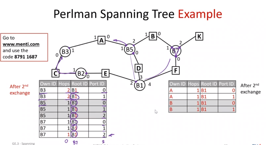
circles: switches(bridges), squares: hubs(terminal,node)
- One bridge is the root Union of shortest paths to root = spanning tree.
- Many spanning trees possible Bridge B2 out of tree Ports in B7, B4 deactivated.
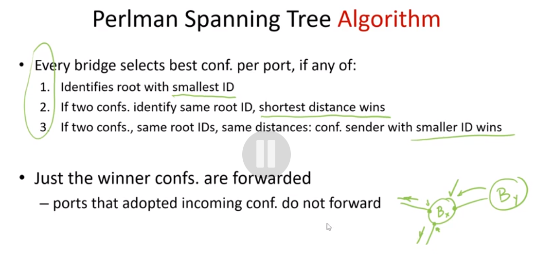
- Rule 1: Root = bridge with smallest ID. B1
- Rule 2: Each network has one designated bridge closest to the root. Each bridge selects the port that gives best path to root. why B3 eliminated
- Rule 3: If two bridges tie in distance from the root, the smallest ID wins Distance = # hops. why loop to B7 disconnected.
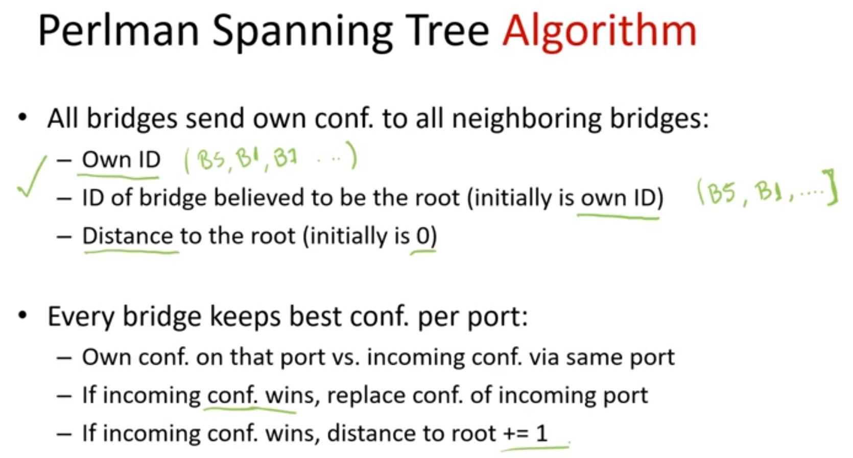
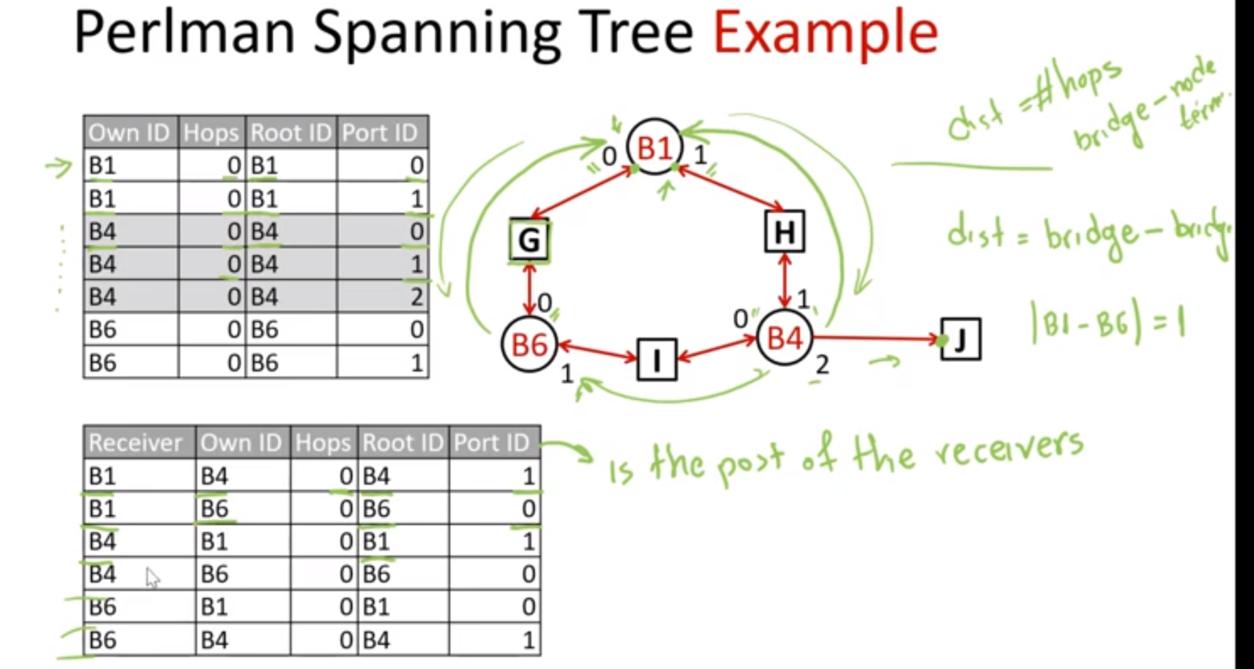
numbers in image below are ports
limitations of bridges: - Forwarding tables can get huge: one entry per node!
- Too much flooding until forwarding tables converge
- Trees can be misbalanced
- Bridges can become hotspots
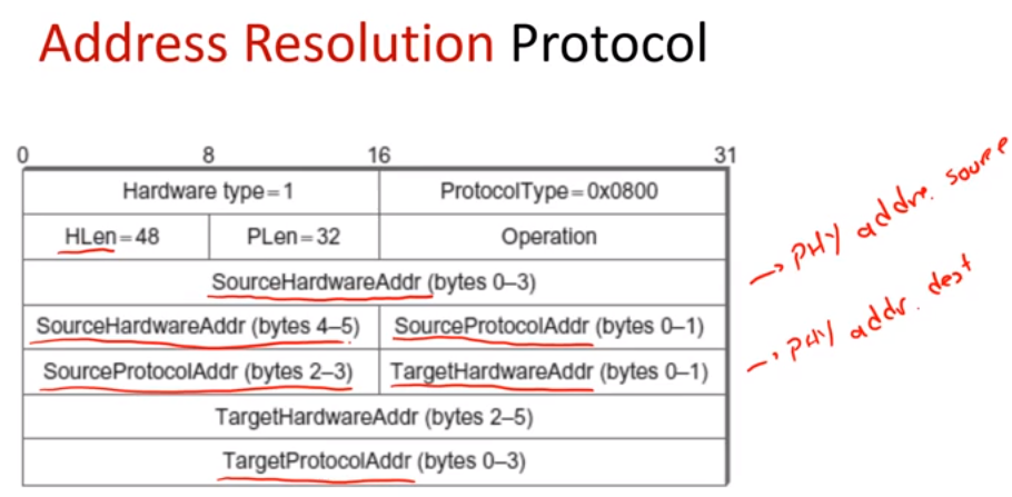
Address Resolution Protocol & L2 to L3 traversal (Link Layer Routing & ARP)
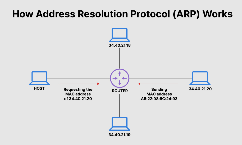
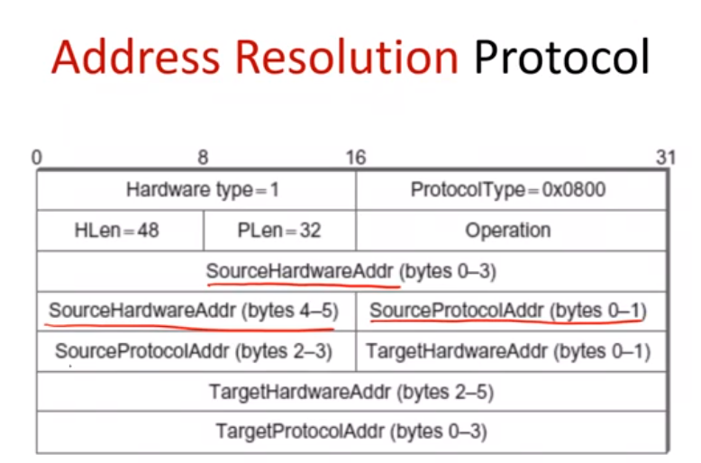
Address Resolution Protocol (ARP) is a protocol or procedure that connects an ever-changing Internet Protocol (IP) address to a fixed physical machine address, also known as a media access control (MAC) address, in a local-area network (LAN).
Address Resolution Protocol - Wikipedia
What Is Address Resolution Protocol (ARP)? | Fortinet
Address Resolution Protocol
Table of IP ←> physical address bindings: entries expire after 15min
Step 1: broadcast request if IP not in table
Step 2: target machine responds with its physical address
Step 3: table refresh at receiver machines
If requestor already in table, restart expiration timer
Else if receiver=target machine, add entry for requestor
Else, do not update
Physical address could be an extra column of routing table
hub: L1
router: L3
left part is L2
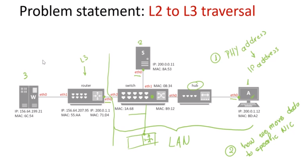
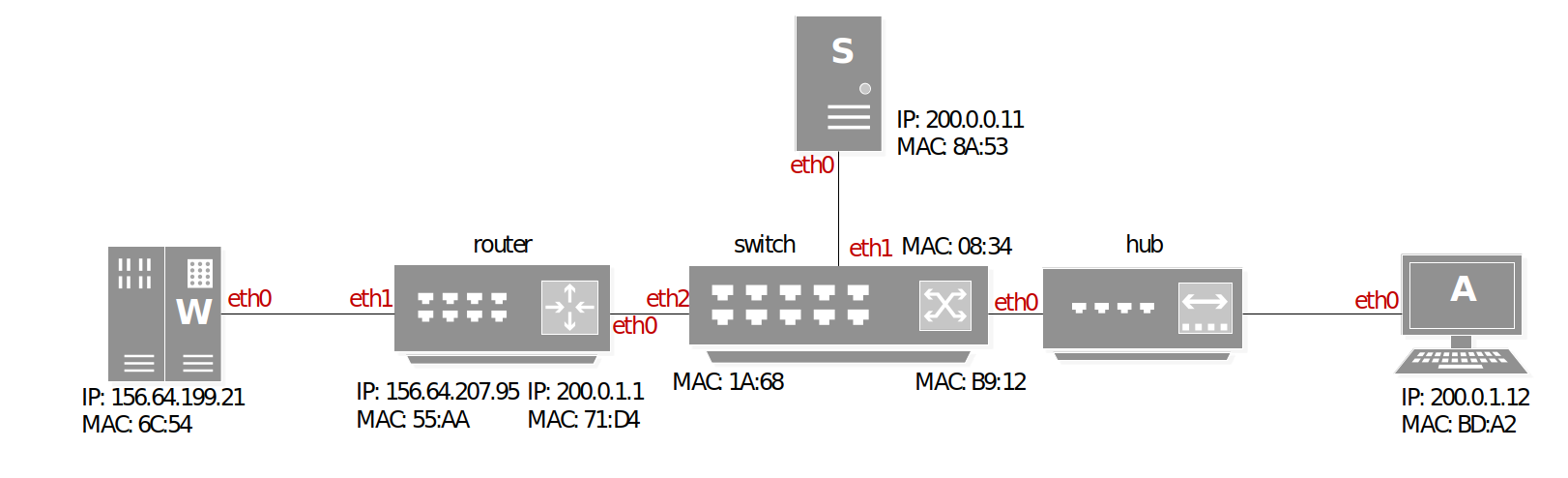
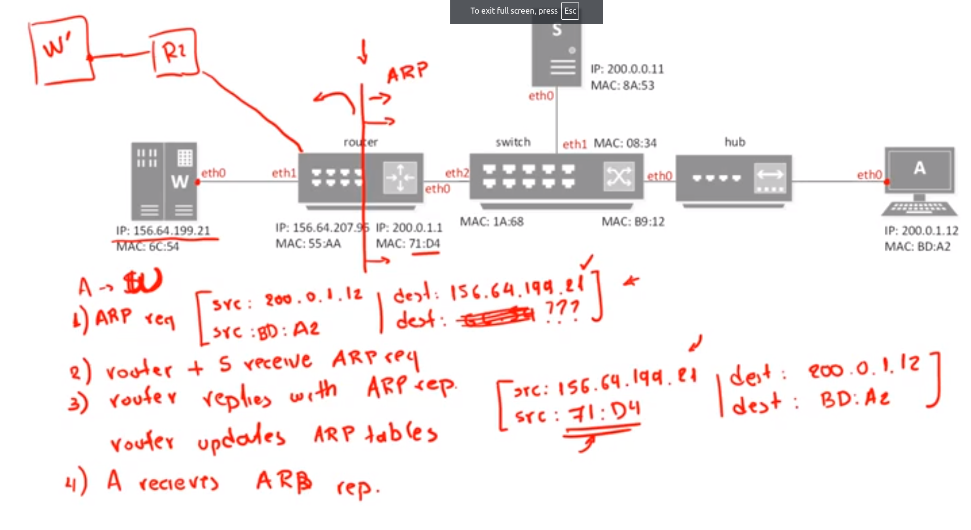
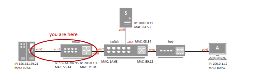
- Assume that every device has empty forwarding tables.
- Show all the steps taken by the network so that HTTP request from A reaches S.
- ARP request with target address 200.0.0.11
- Router rejects the request as target is in same domain as requestor
- S replies with own MAC address
- Frame composed and sent to MAC 8A:53
- Switch checks on forwarding table and forwards directly to S
- IP identifies target address 156.64.199.21 is out of local domain. Go to gateway 200.0.1.1
- ARP request with target address 200.0.1.1
- Router replies with own MAC address 71:D4
- Frame composed and sent to MAC 71:D4
- Router checks on routing table and forwards directly through eth1 to 156.64.199.21
Traversal Exercise
Forwarding (link layer): select an output port based on destination address and routing table.
Routing (network layer): process by which routing table is built.
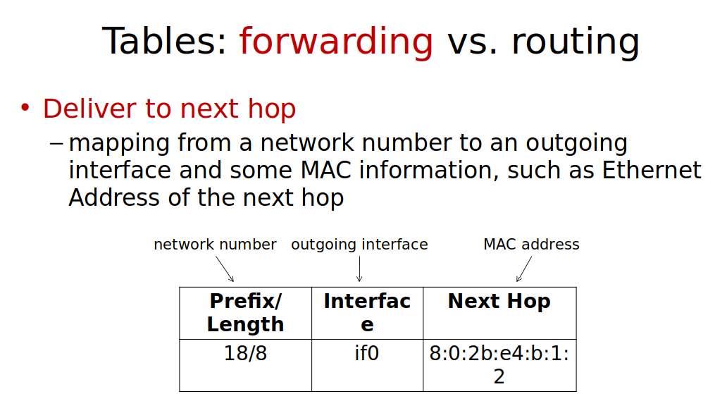
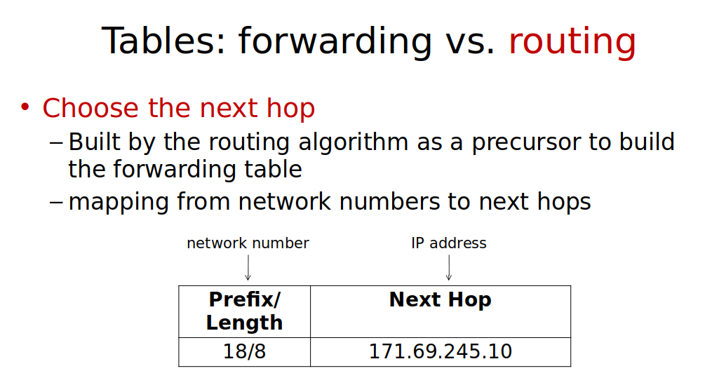
routing tables:
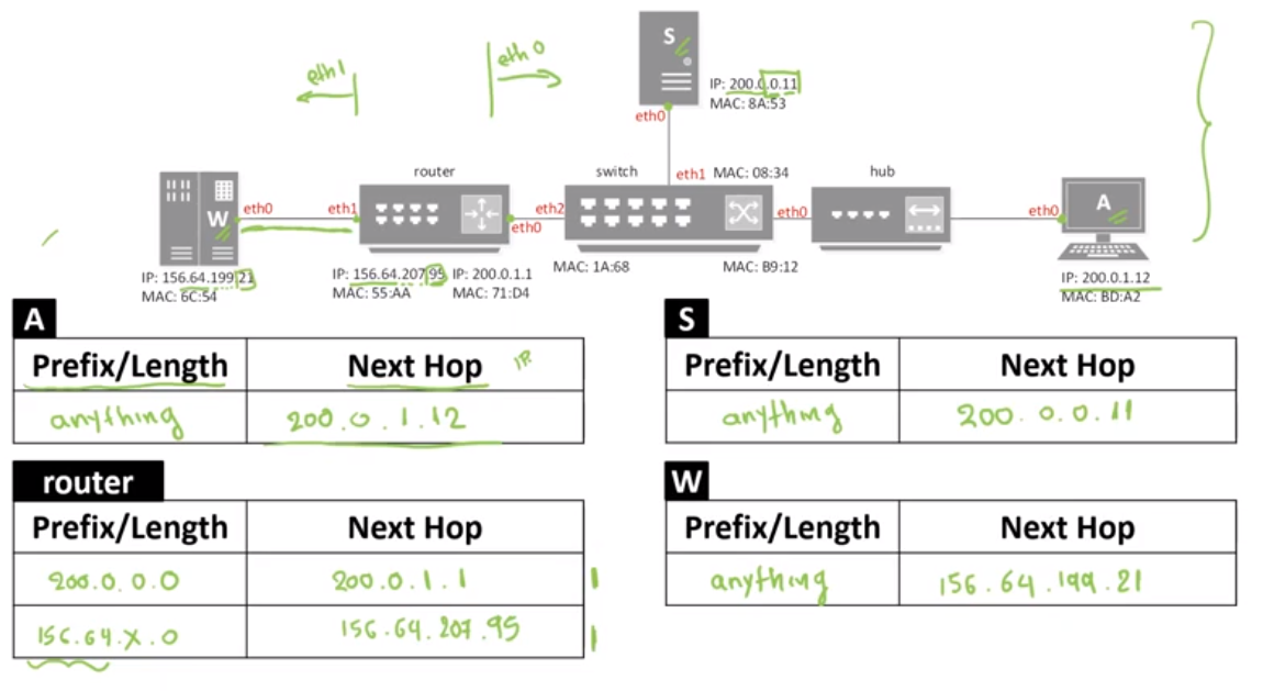
router: L3
everything before the router to the right: L2
hub: L1 so we skip it since A is L2
Assume that every edge device has empty forwarding tables. Show all the steps taken by the
network so that HTTP request from A reaches S and another one reaches W.
S:
- ARP request with target address 200.0.0.11
- Router rejects the request as target is in same domain as requestor
- S replies with own MAC address
- Frame composed and sent to MAC 8A:53
- Switch checks on forwarding table and forwards directly to S
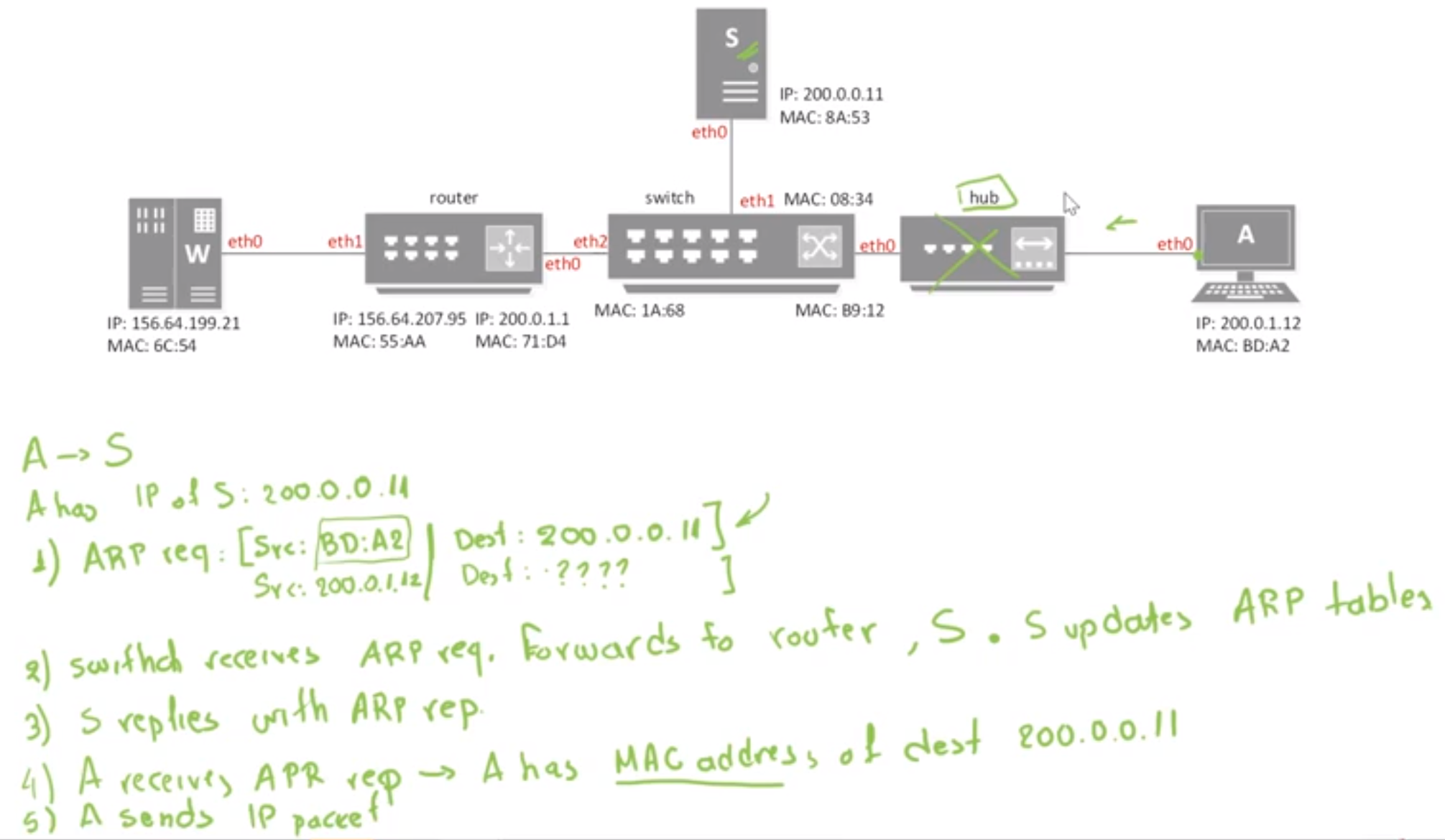
W: - IP identifies target address 156.64.199.21 is out of local domain. Go to gateway 200.0.1.1
- ARP request with target address 200.0.1.1
- Router replies with own MAC address 71:D4
- Frame composed and sent to MAC 71:D4
- Router checks on routing table and forwards directly through eth1 to 156.64.199.21
Internetworking & Reliable Transport
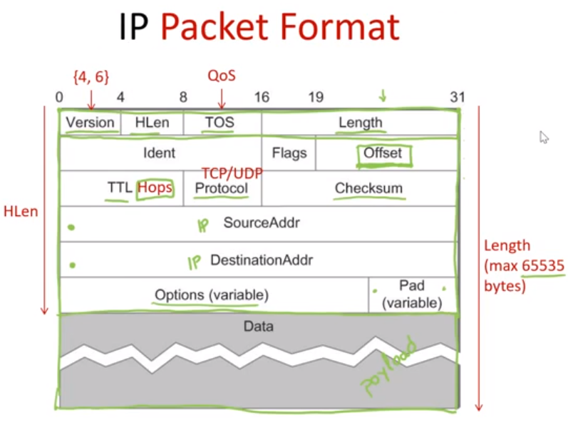
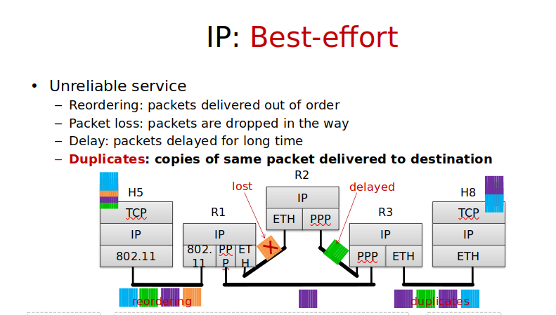
Internet Protocol Packets
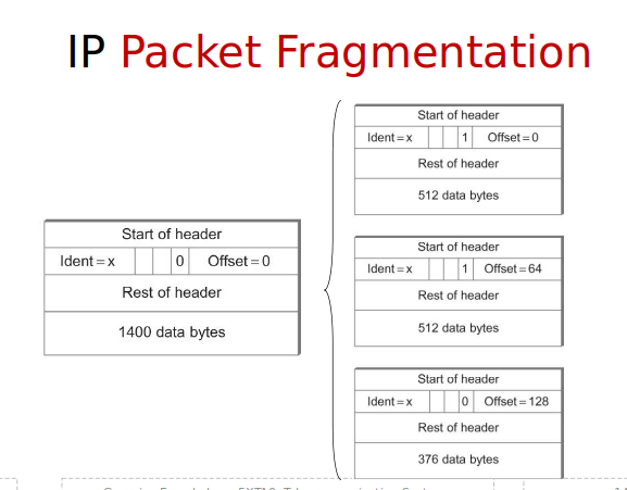
IP Packet Fragmentation
- One IP packet split into multiple link-layer packets
- One IP packet split into multiple link-layer packets
- Indent (Identifier of fragment sequence), Flags(More fragments to follow?), Offset (pointer to the first byte from original IP packet this payload corresponds to measured in 8-byte blocks)
IP Datagram Forwarding
IP address classes explained | class A , B ,C ,D ,E | Free CCNA 200-301 - YouTube
IP Subnets
Classless Inter-Domain Routing - Wikipedia
Subnet - Wikipedia
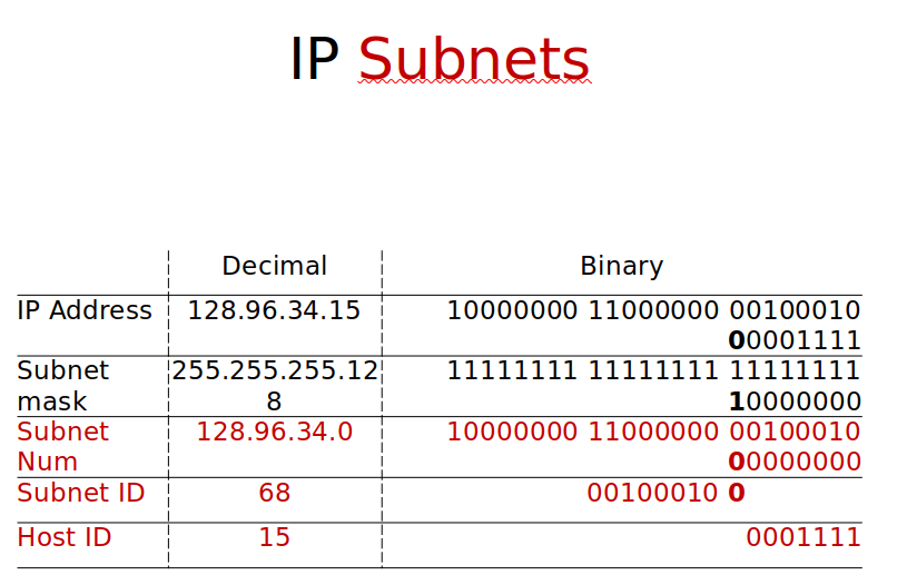
split the last part of IP from host id to subnetid.hostid
- Physical networks with same Network ID
- Network IDs from class A or B addresses
- IP split:
- Network IDs from class A or B addresses
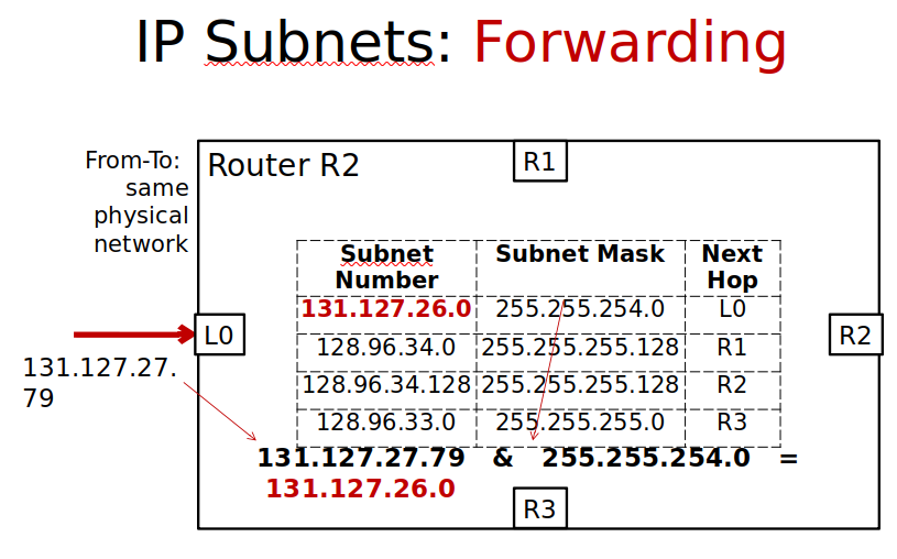
- subnet_mask AND ip_address = subnet_number
- subnet_number =
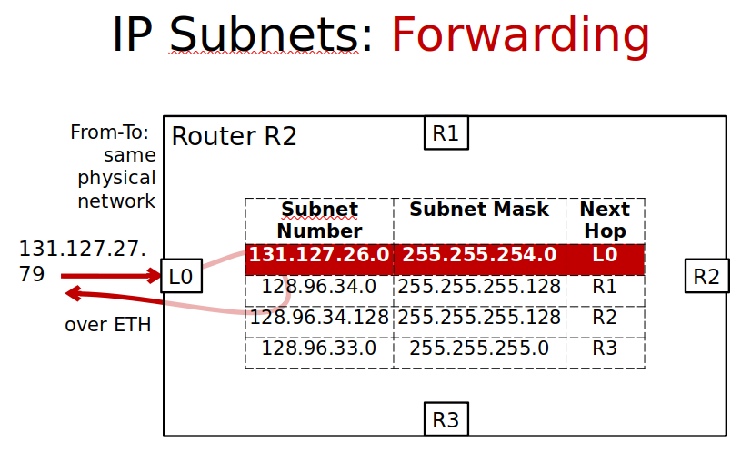
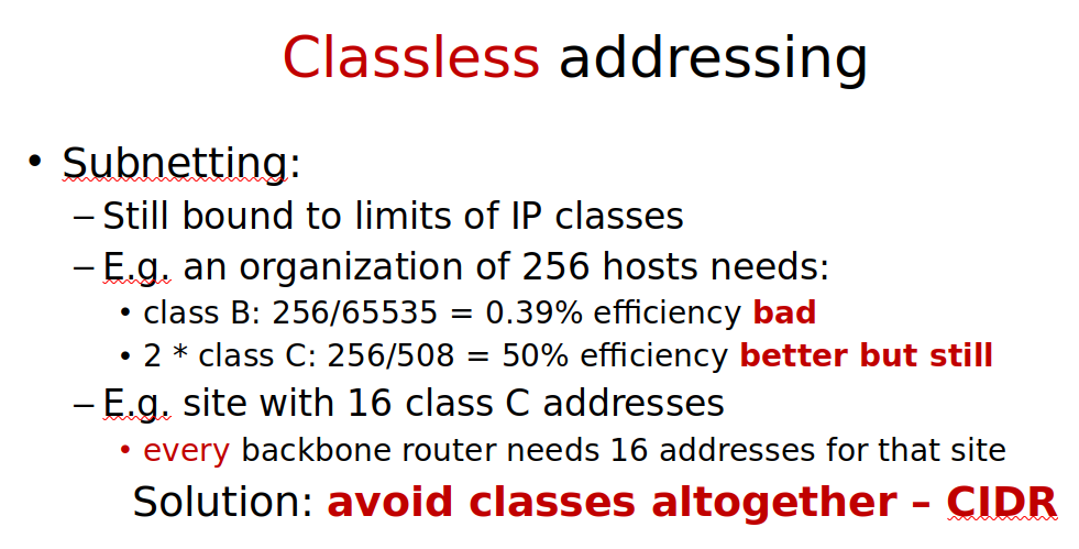
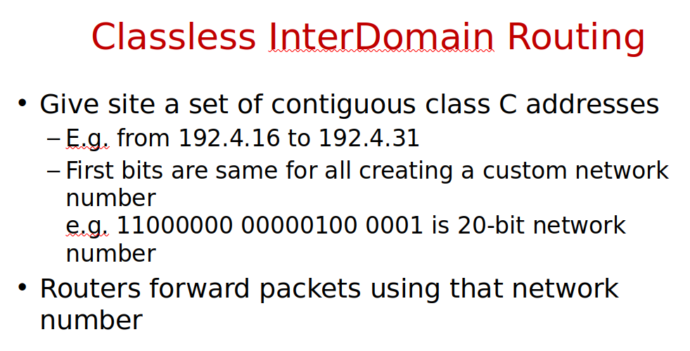
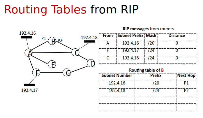
- Group addresses under common prefixes
- Instead of subnet masks use /X notation
- Assumed subnet masks of X first bits equal to 1
- 192.4.16/20 represents all addresses from 192.4.16 to 192.4.31
If ethernet address known, route to IP router…
IP characteristics, packet structure & fragmentation…
IP addresses, subnetting, forwarding tables…
Classless Addressing…
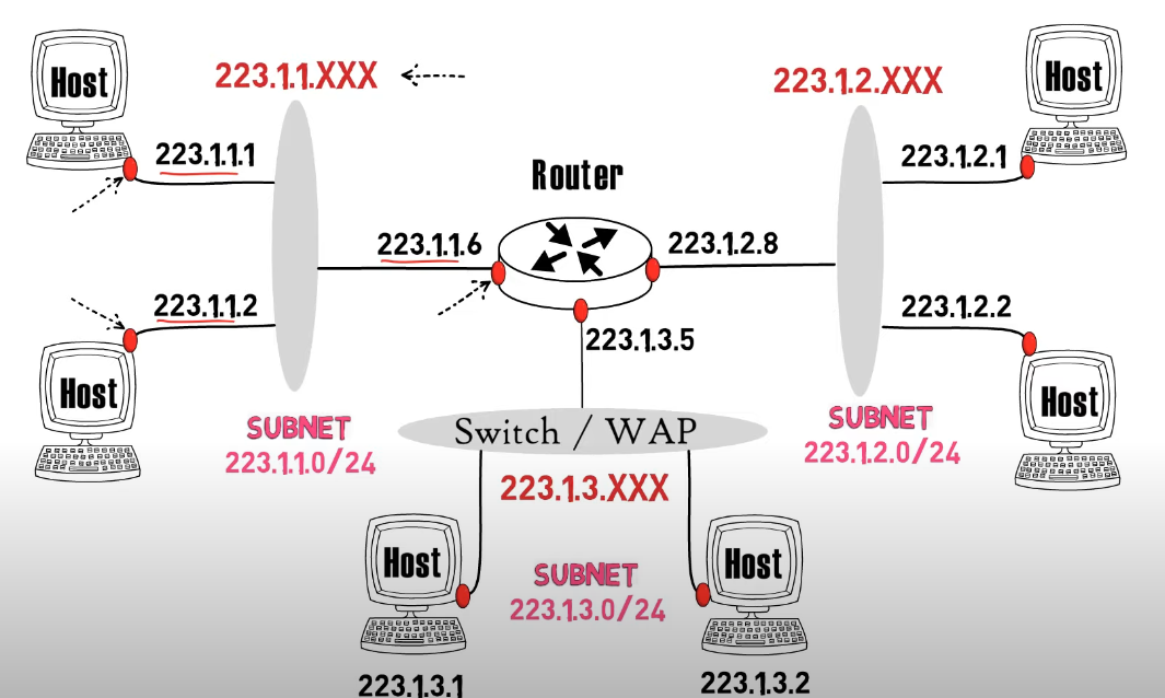
/24 subnet indicating that the first 24 bits are common. since 8bits.8bits.8bits.8bits
IP addressing and Subnetting | CIDR | Subnet | TechTerms - YouTube
Distance Vector Routing
- determines the best route for data packets based on distance.
- find lowerst cost path between nodes
- dynamic approach: distance vector path built during…
Distance-vector routing protocol - Wikipedia
Routing Information Protocol - Wikipedia
Bellman–Ford algorithm - Wikipedia
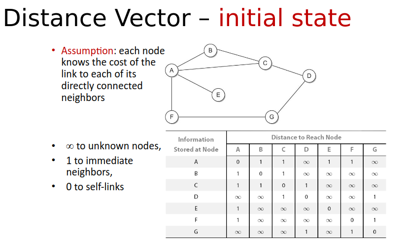
each node(router) has a cost, and it is shared with neighboring nodes.
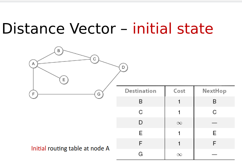
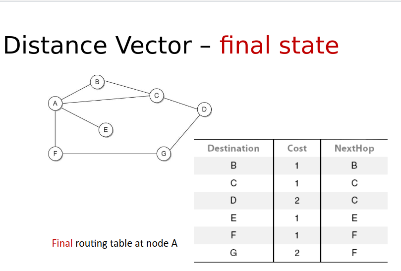
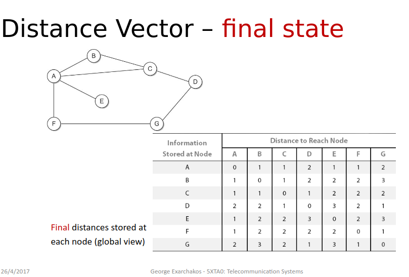
Bellman ford:
- each router had original vector of costs to all other routers
- every (T sec) each router sends its routing table to neighbour
- each router updates its table based on info
- can deal with node failures/instability
Route Poisoning and Count to infinity problem in Routing - GeeksforGeeks
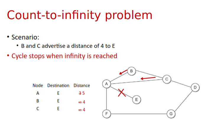
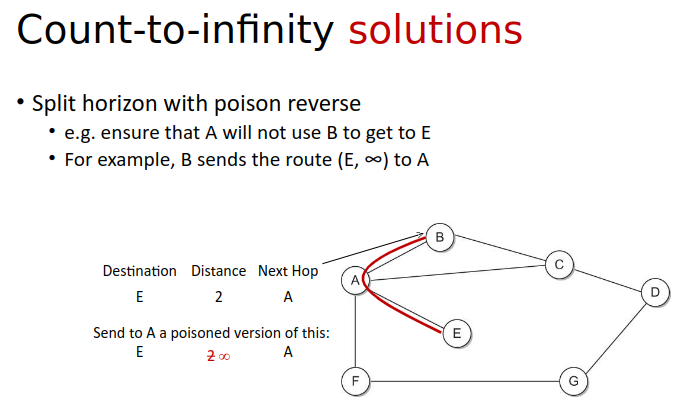
- connection to E cut so A gets stuck in a loop with (B,C) in cost distance to E…
- sol1: small num to approx infinity eg: 16
- sol2: split horizon, no routesl earned from neighbour back to neighbour
- sol3: split horizon poison reverse
Split horizon route advertisement - Wikipedia
Routing Information Protocol - Wikipedia
To prevent routing loops, RIP imposes a limitation on the number of hops allowed in a path from the source to the destination.
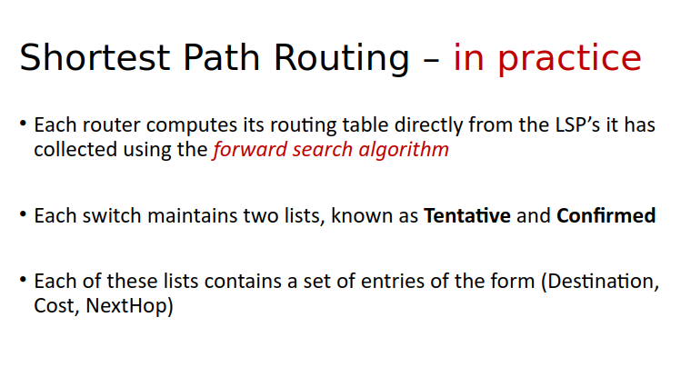
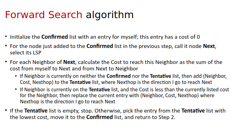
Link State Routing
Link-state routing protocol - Wikipedia
Open Shortest Path First - Wikipedia
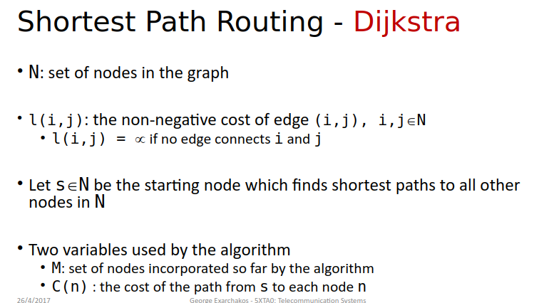
Dijkstra’s algorithm - Wikipedia
-
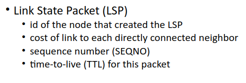
This contrasts with distance-vector routing protocols, which work by having each node share its routing table with its neighbors, in a link-state protocol the only information passed between nodes is connectivity related.
-
OSPF uses Djikstra
-
The cost factors may be the distance of a router (round-trip time), data throughput of a link, or link availability and reliability, expressed as simple unitless numbers.
-
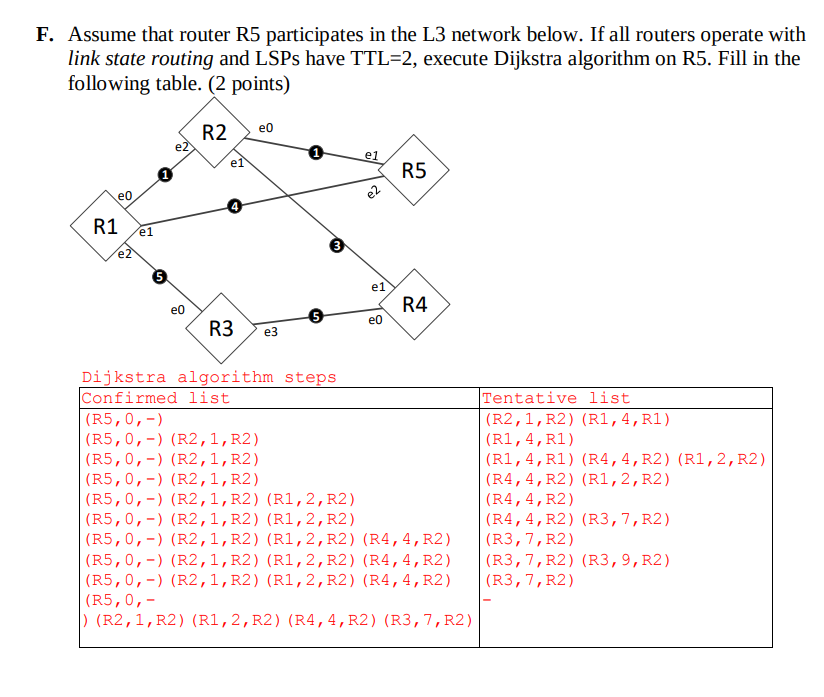
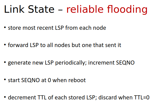
TTL (Time to Live) determines how far a Link State Packet (LSP) can travel within the network. It limits the number of hops an LSP can make starting from its originator.
-
static approach: pre calculate path.
-
sends info to all nodes not only neighbors.
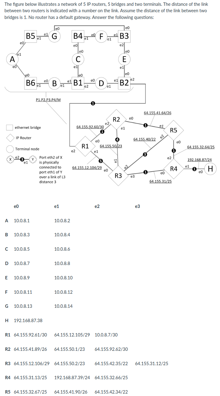
Practice
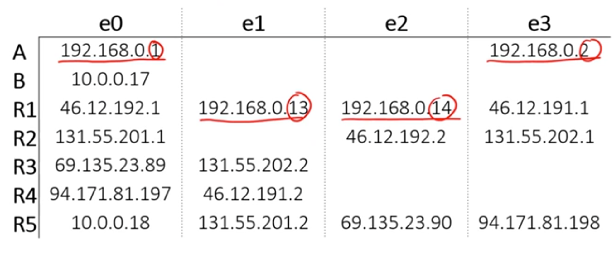
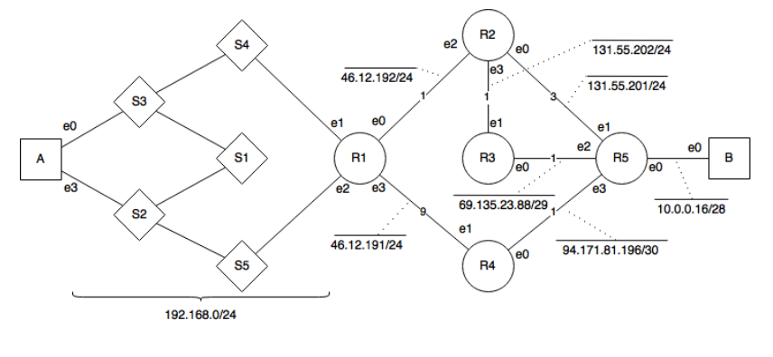
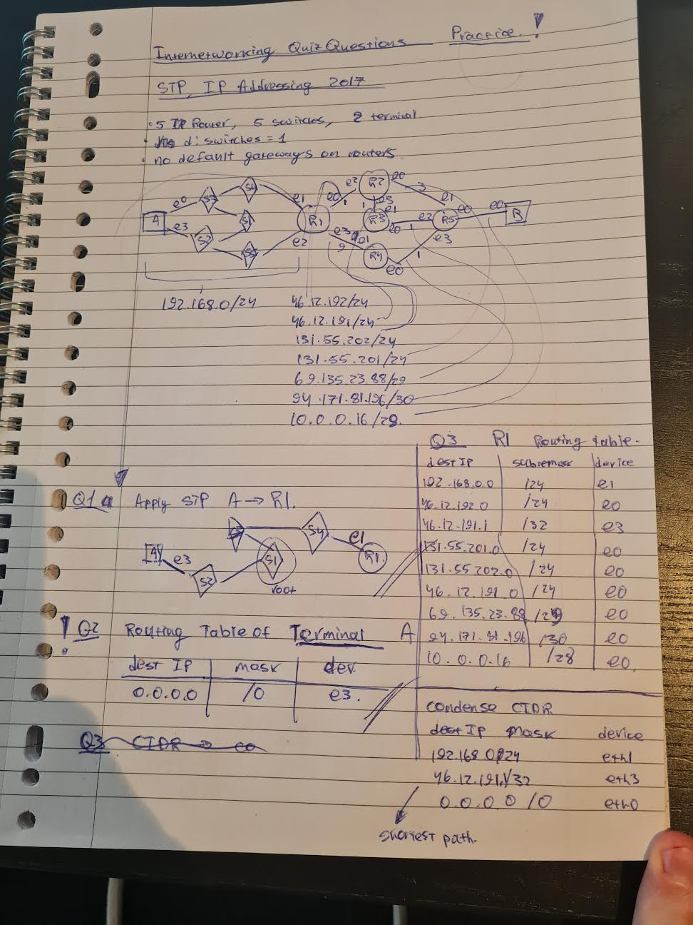
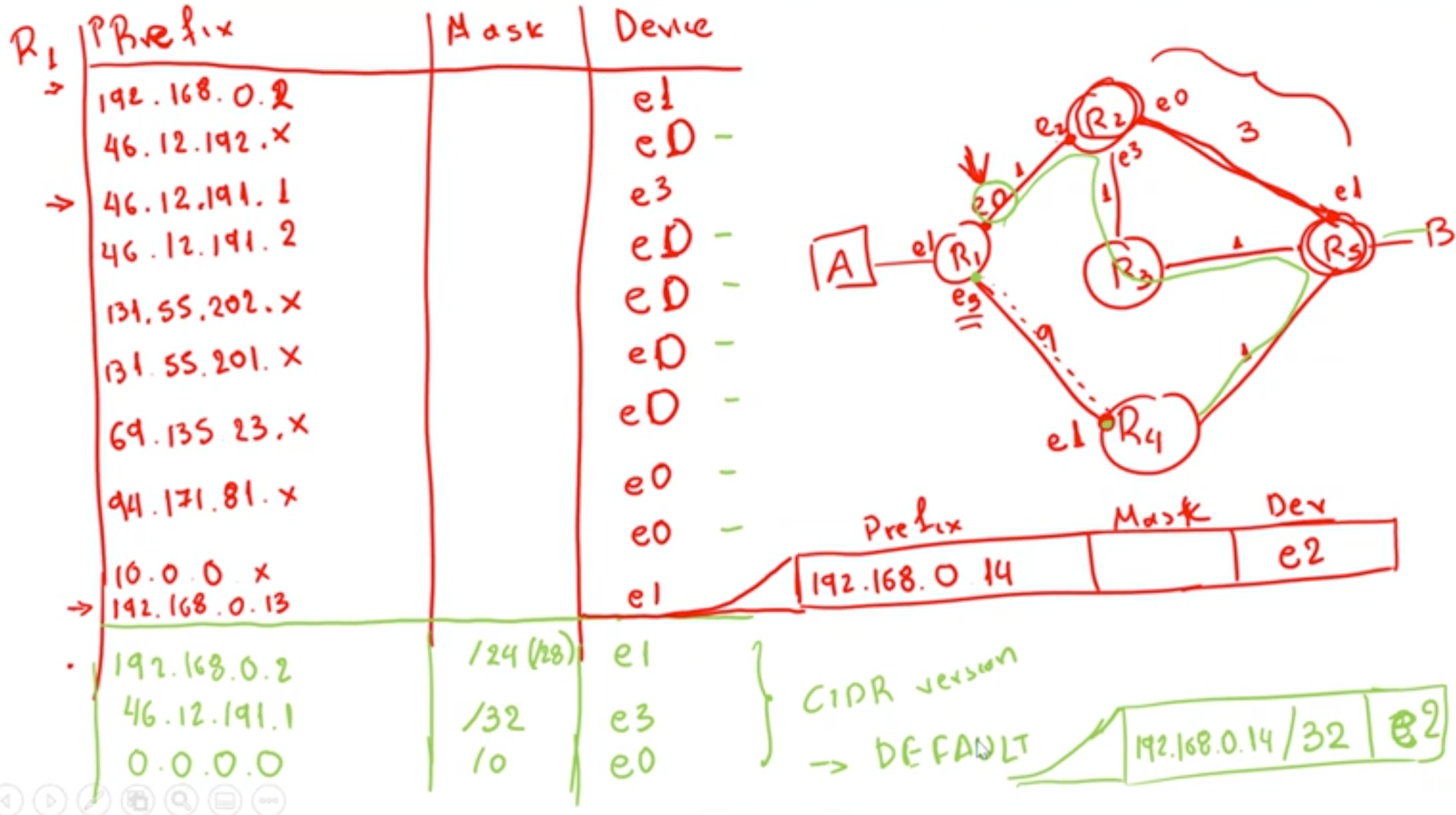
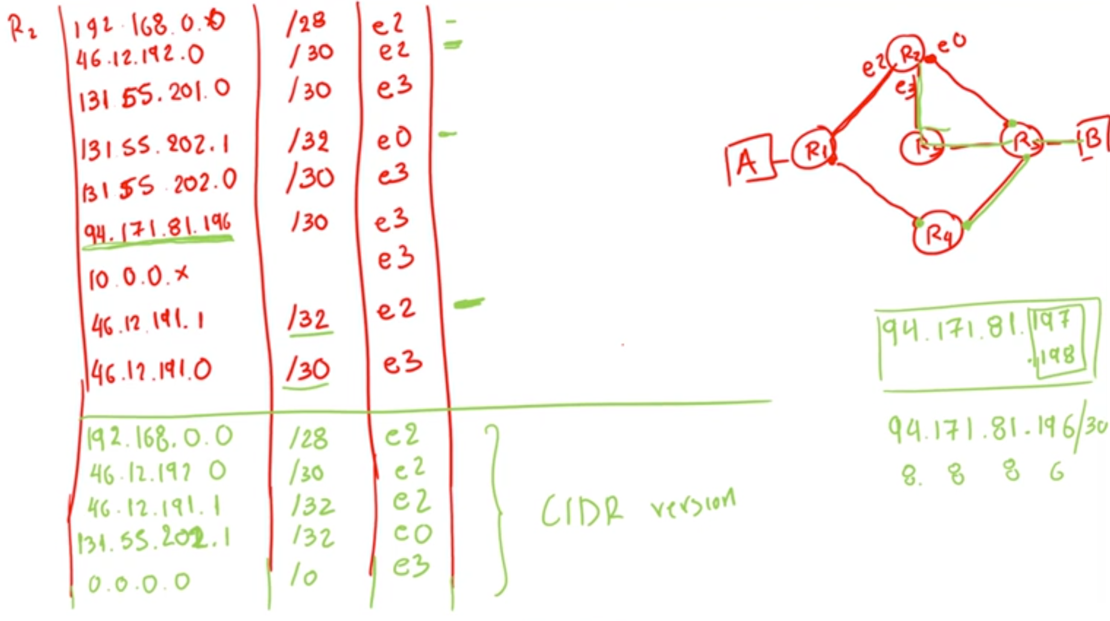
- terminal routing table is always a default gateway
- routing table of a router will always have a default gateway at e0
- the connecting route TO R1 (copy) of actual
- the connecting route FROM R1 changed to (/32) to specify unique network
- S1 is root since it has the smallest cost
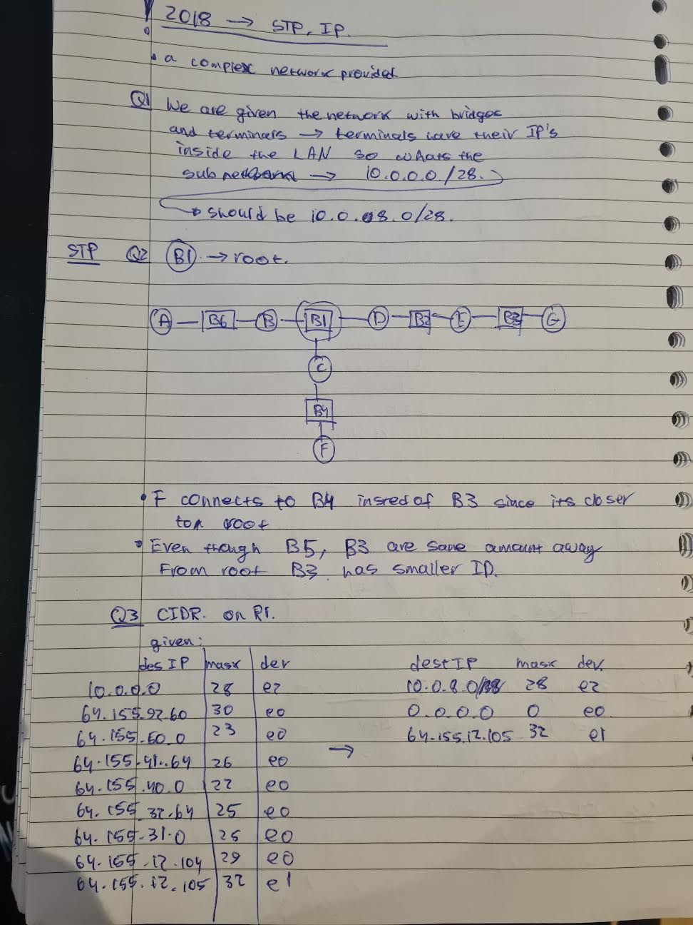
…