5EPB0 Electromagnetics II
- Area: Electromagnetics and Waves
- Topics: Vector Calculus · Maxwell Equations · Plane Waves and Reflection · Transmission Lines · Waveguides · Antennas and Radiation · S-Parameters and Impedance Matching
- Related courses: Electromagnetics I - 5EPA0 · Components in Wireless Technologies - 5XTC0 · Photonics - 5XTB0
General notes
Topic: Vector Calculus
Plane wave - Wikipedia
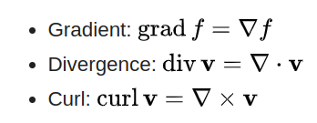
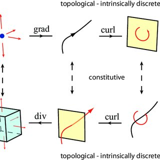
result of a gradient is a vector field, while the result of a divergence is a scalar field.
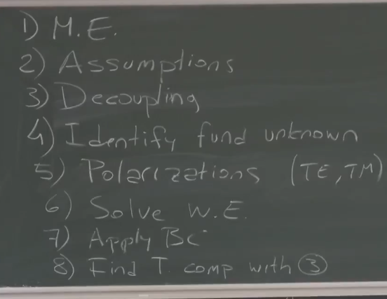
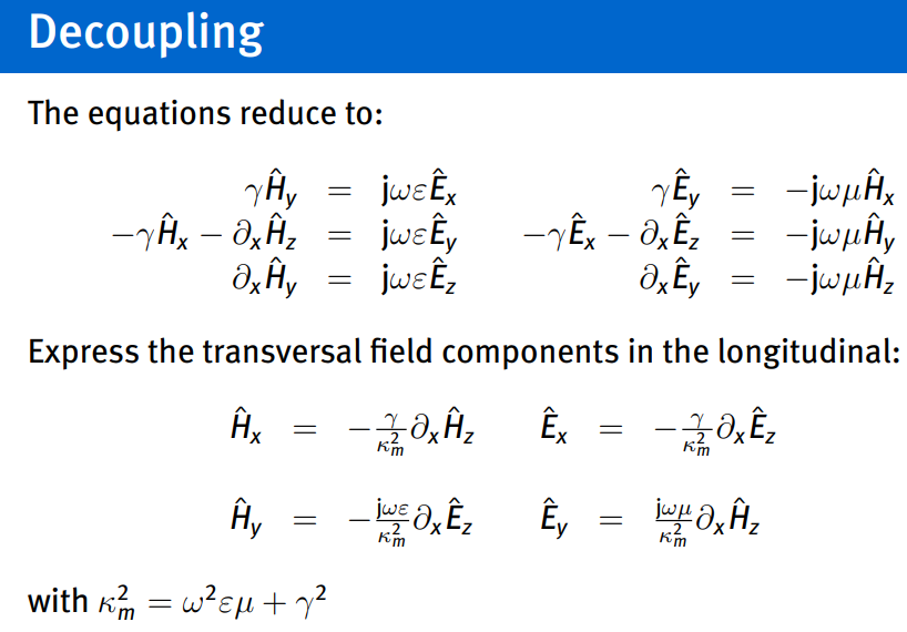
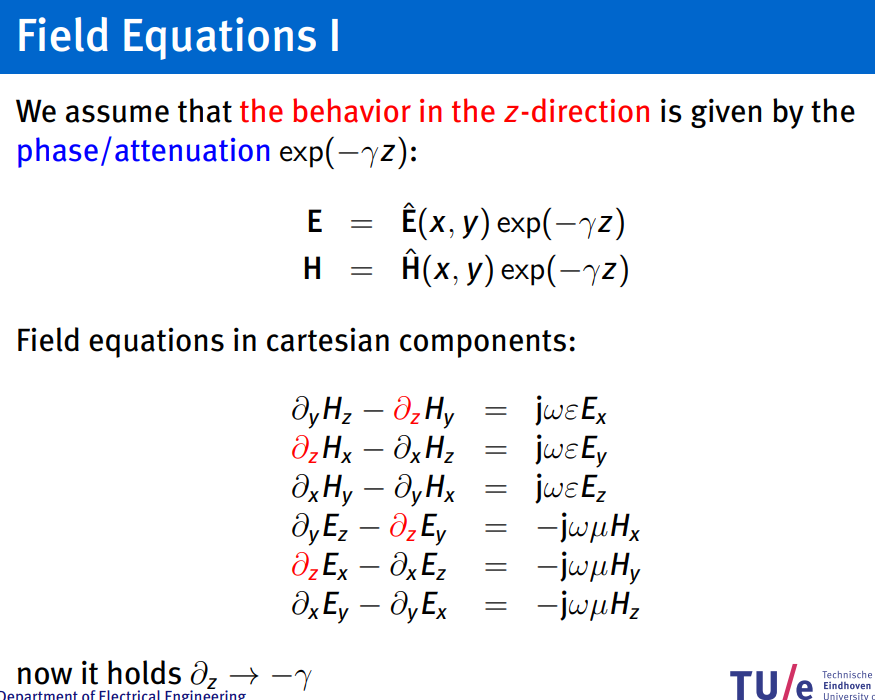
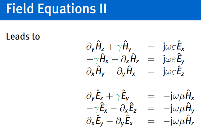
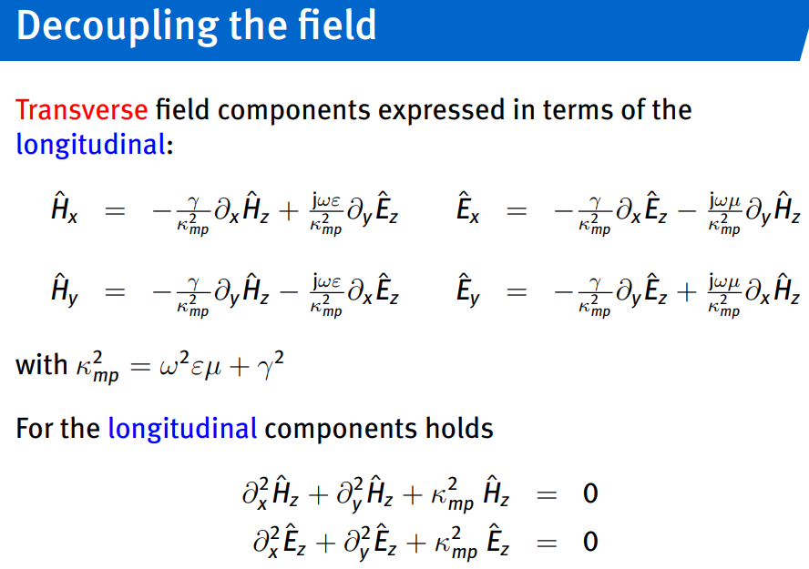
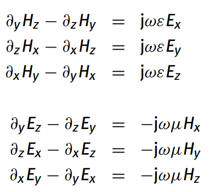
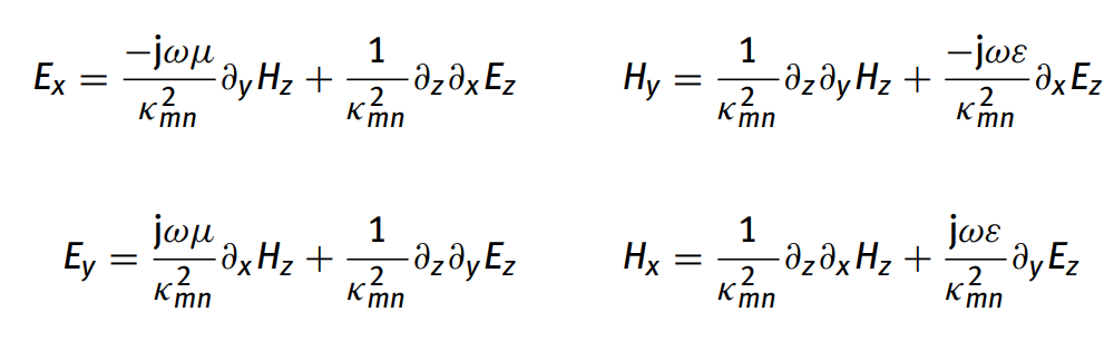
decoupling: express transverse components in longitudinal. (4 transverse components based on 2 longitudinal…)
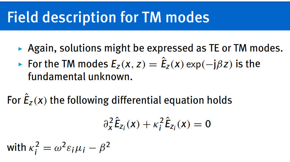
fundamental unknown usually:
solve W.E→for fundamental unknown…
Waves in time and one spatial dimension
Summary
Special cases:
matched → no reflection → open circuit → total reflection with same polarity → short circuit → total reflection with inverted polarity →
Detailed notes
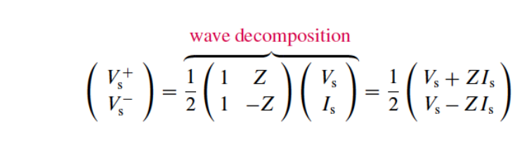
DON’T FORGET THE MINUS SIGN WHEN DECOMPOSING FOR CURRENT I-
LEARN CIRCUIT ANALYSIS BETTER
Uniform Plane Waves: A 3D Journey to the Simplest Electromagnetic Wave Propagation
Transmission Lines: Part 1 An Introduction
Maxwell Equations
But how exactly do the voltage and current propagate through transmission lines?
Characteristic impedance
What is the difference between characteristic impedance and input impedance in transmission lines
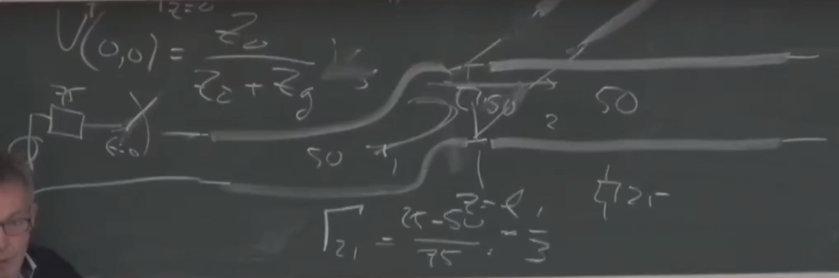
Transmission coefficient
Reflection coefficient
Uniform plane waves
Topics: Maxwell Equations · Plane Waves and Reflection
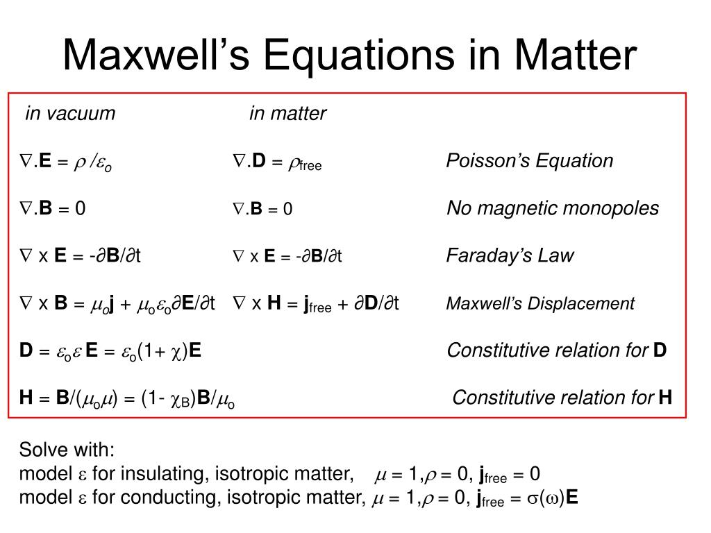
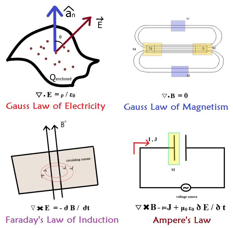
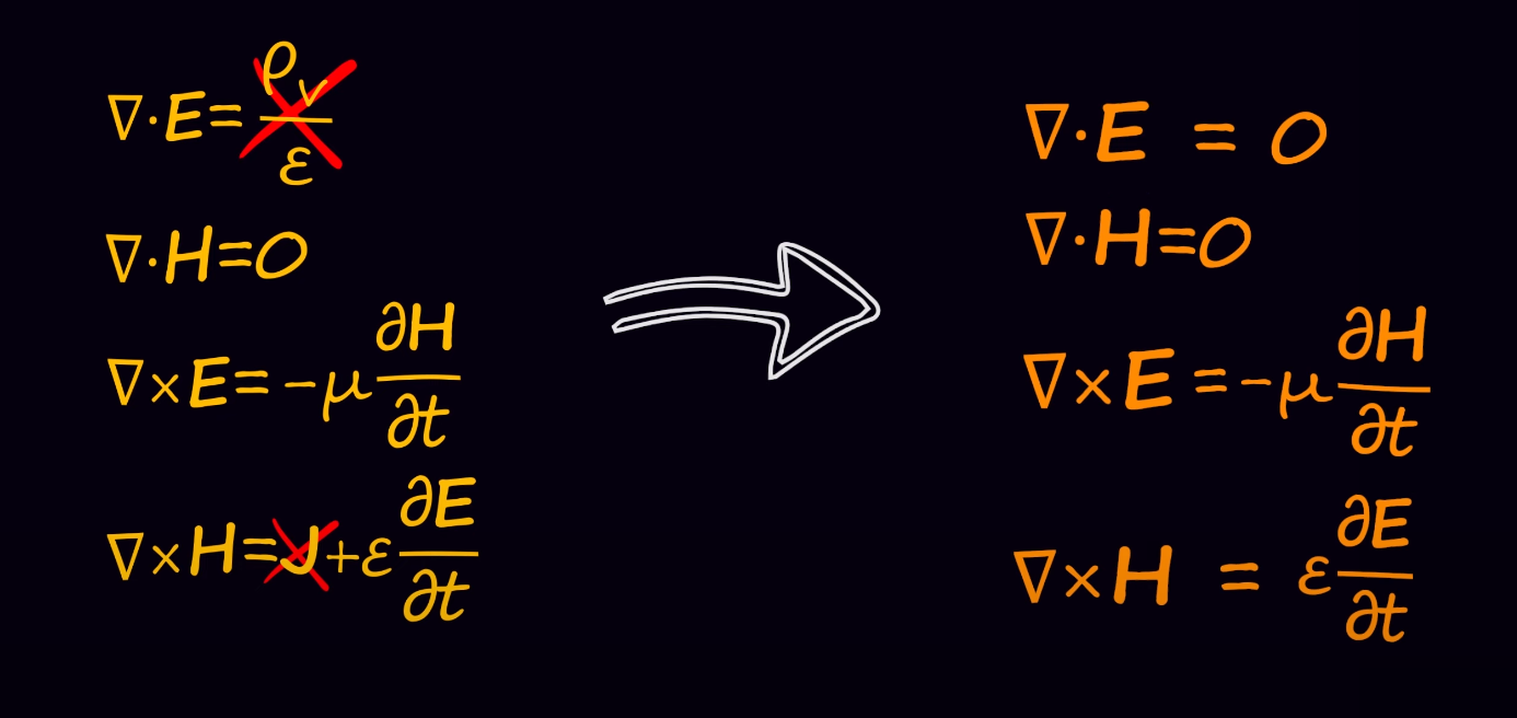
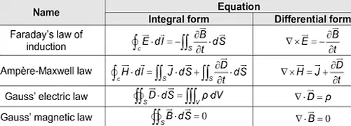
source free region
divergence:
uniform plane waves only depend on time, one cartesian coordinate
two coupled systems (right hand rule (thumb: E field, middle: Z, point: H)):
voltage current amplitudes (another way to represent a coupled system do (right hand rule))
TL equations for uniform plane wave:
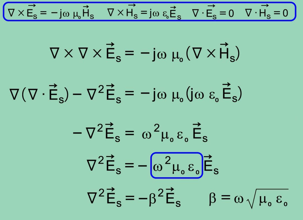
wave equation:
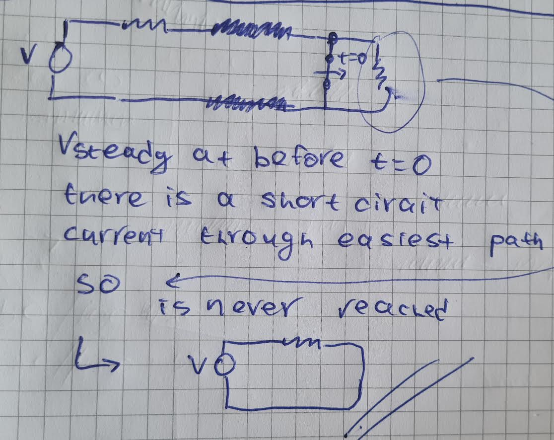
at steady state TL is ignored
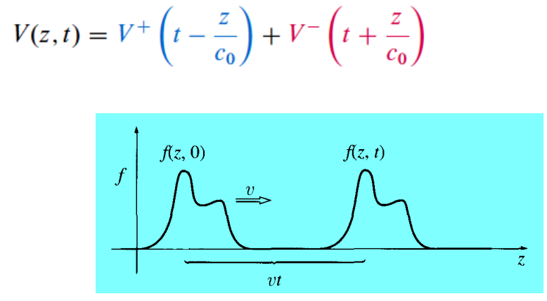
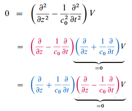
-: progressive wave; +: regressive wave
impedance
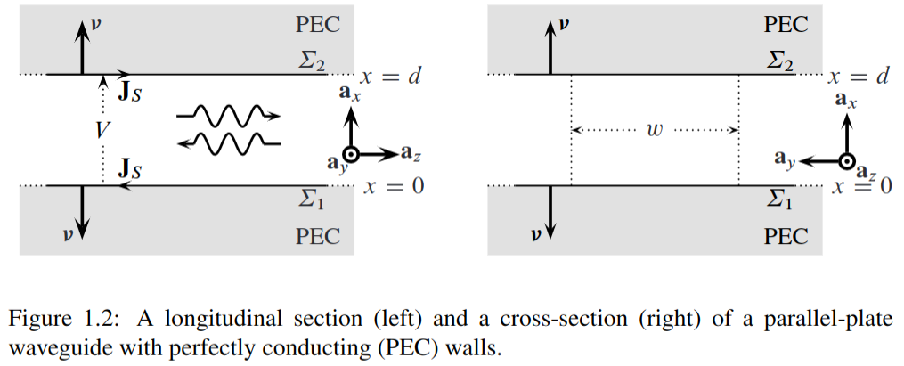
TEM-wave propagation along transmission lines (Transverse)
Topic: Transmission Lines
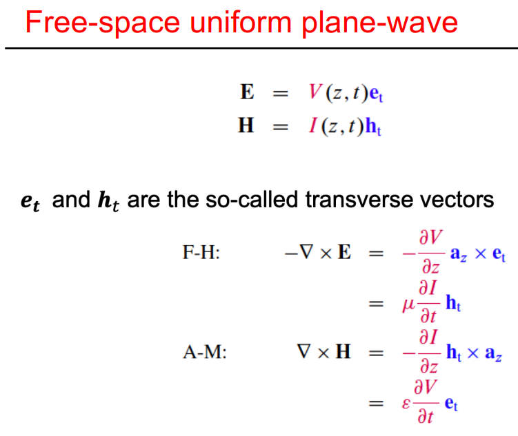
characteristic impedance (only when waves propagated not during steady state ):
lumped components:
Wave reflection
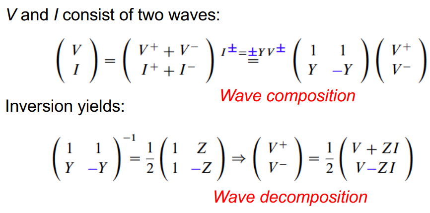

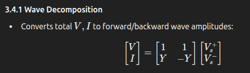
composition:
decomposition:
when OC there is also no forward backward propagating waves
when there sudden OC → compensation
losses lower the amplitude instead of infinite propagation/reflection.
time domain reflection (TDR): used for cable testing: quick pulse with switch.
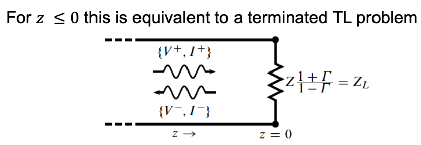
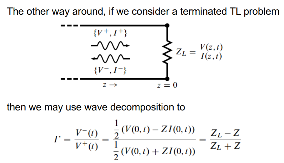
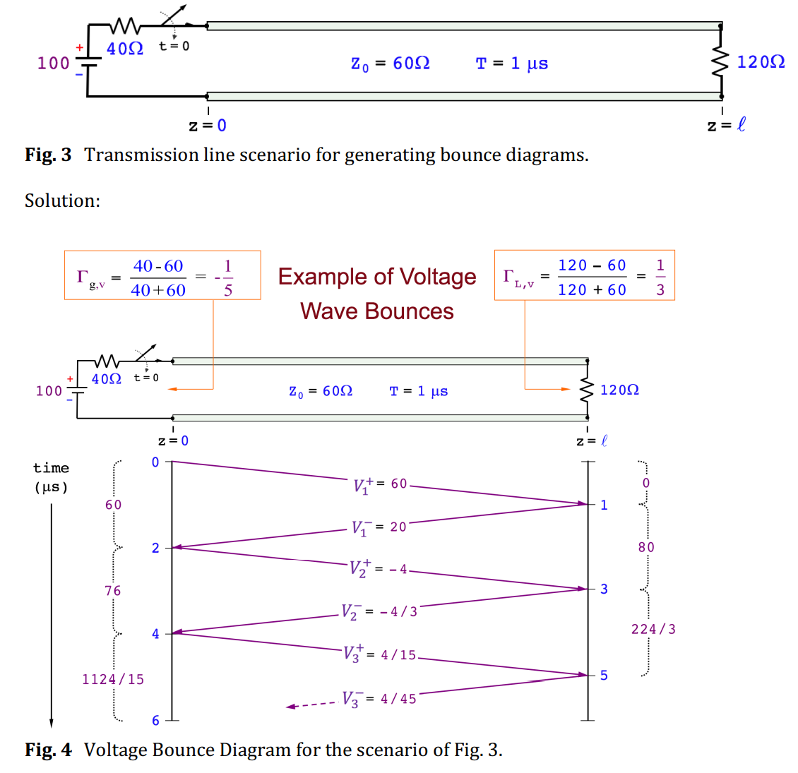
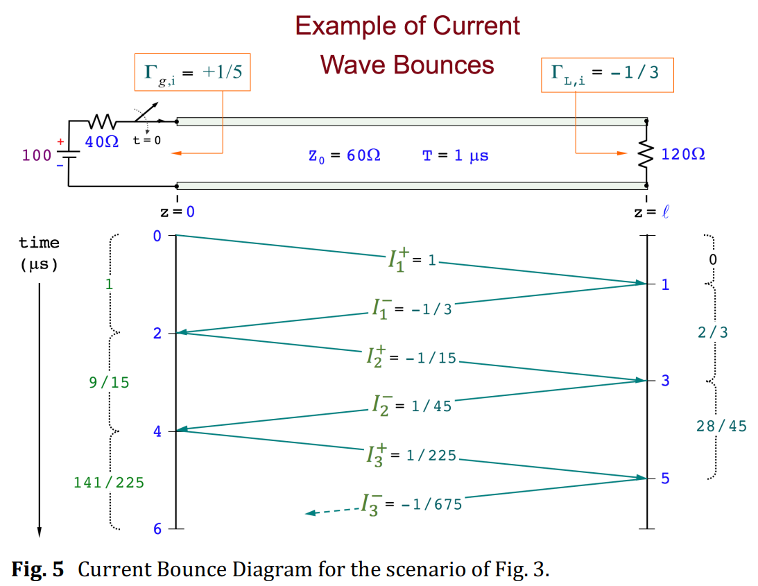
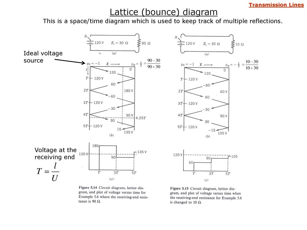
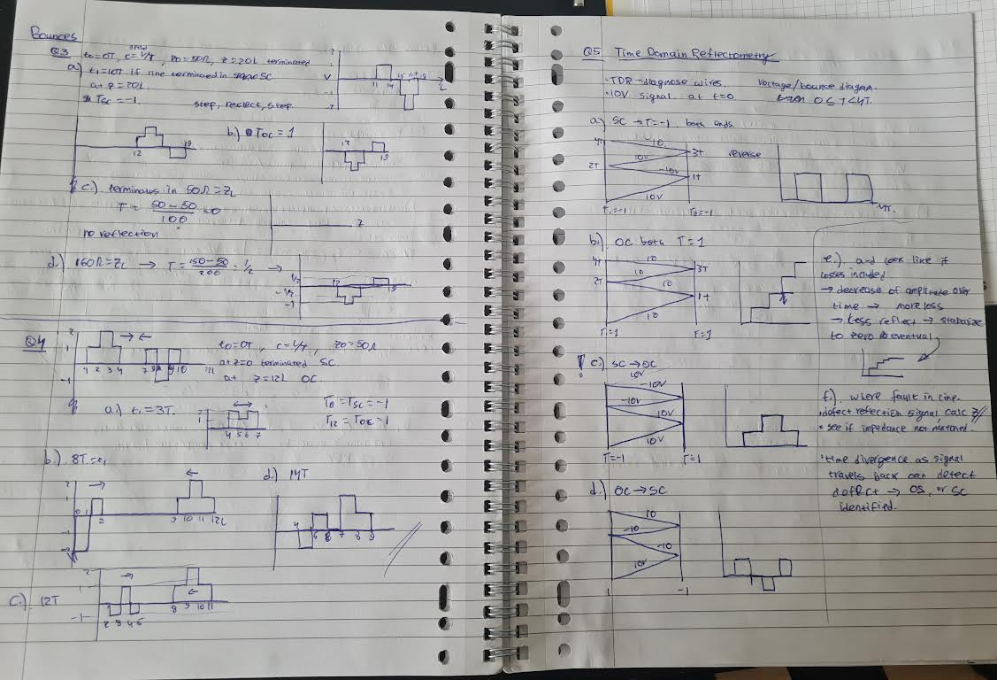
Transmission lines reflection and transmission
Topic: Transmission Lines
Summary
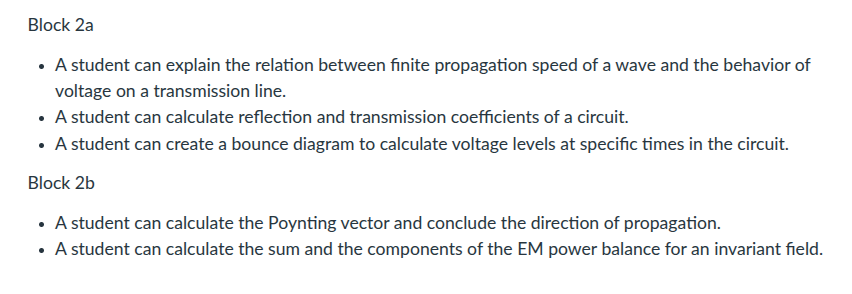
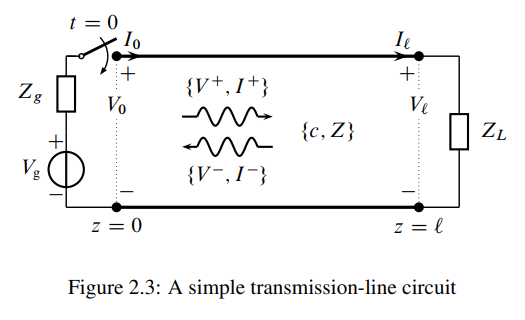
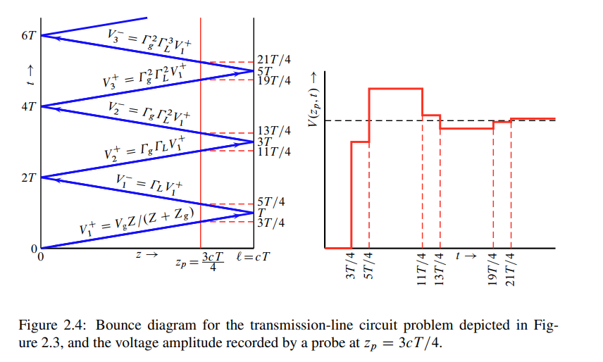
Detailed notes
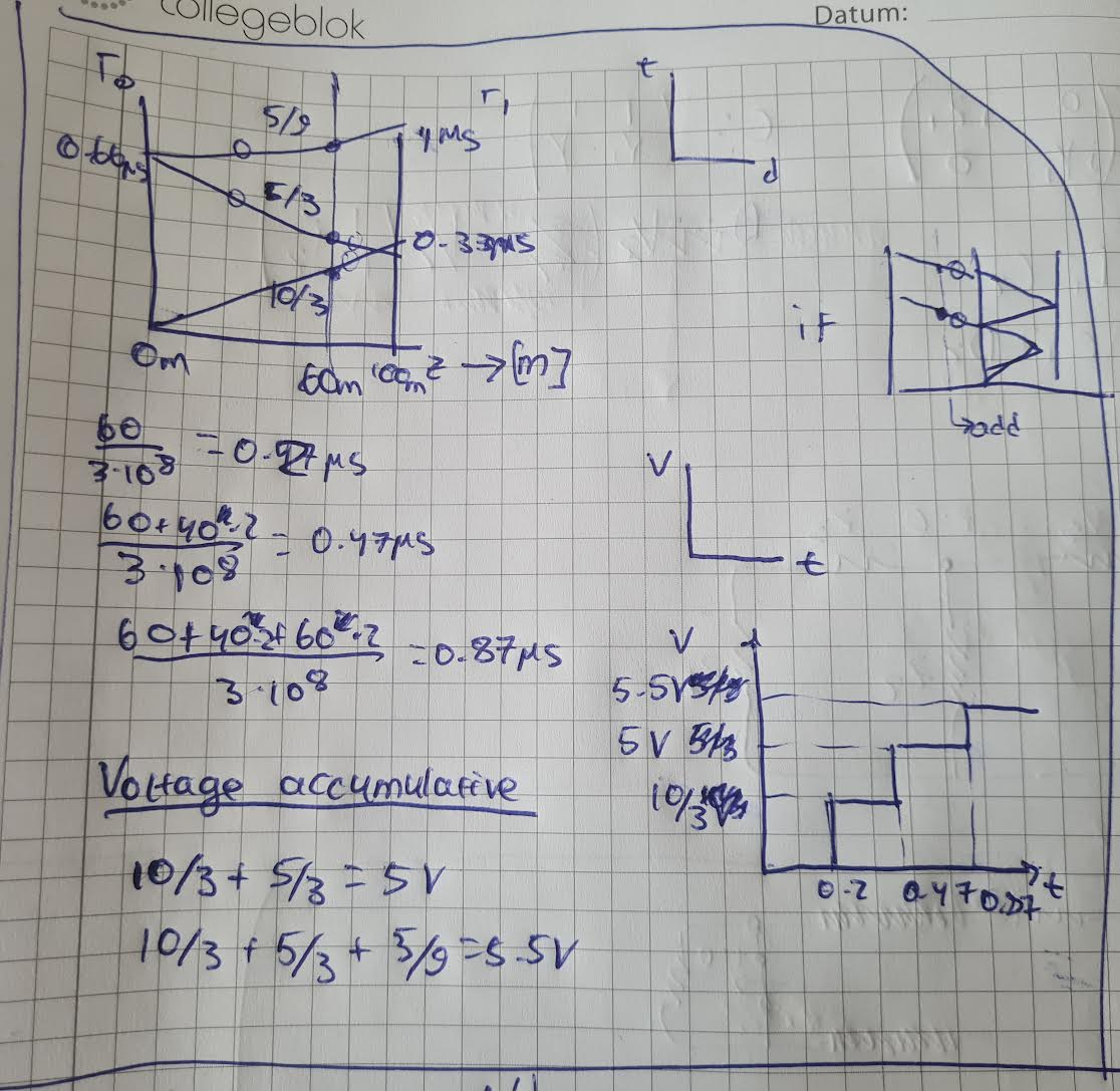
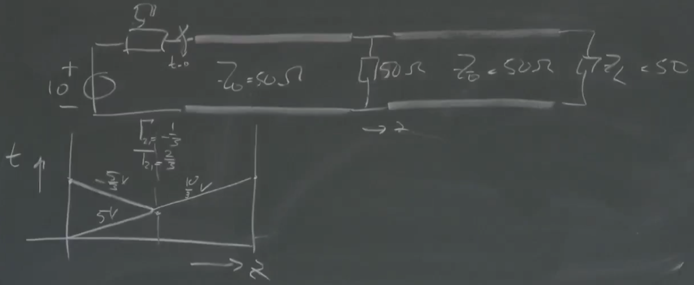
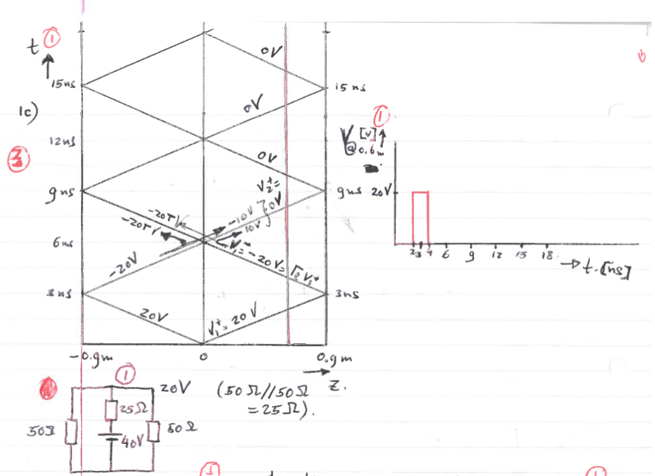
Boundary conditions for penetrable media & Reflection and Transmission & Bounce diagrams
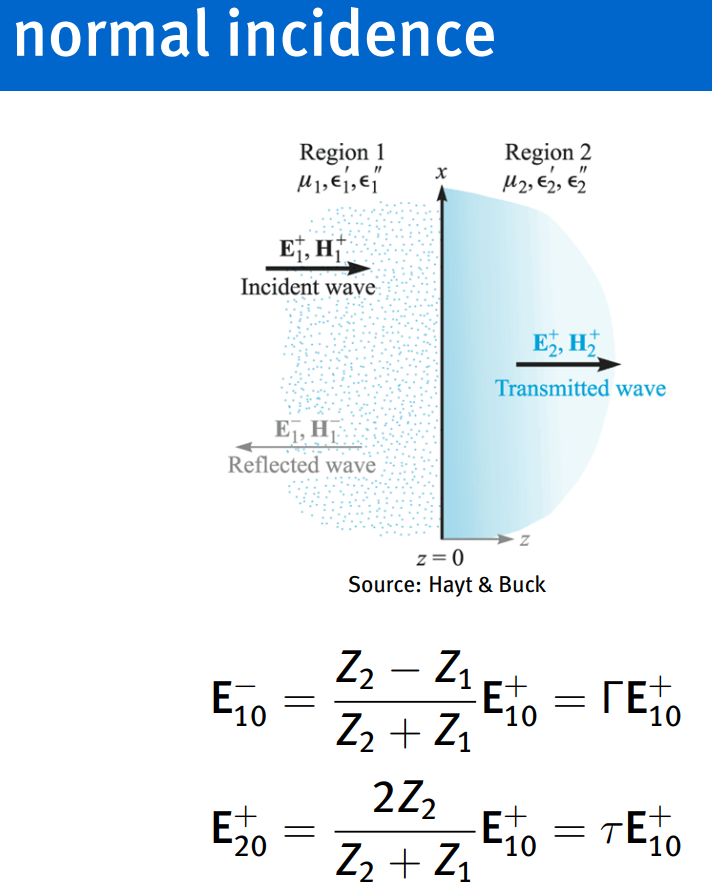
incident, reflected, transmitted field
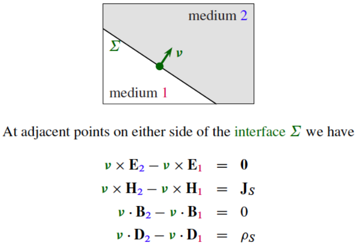
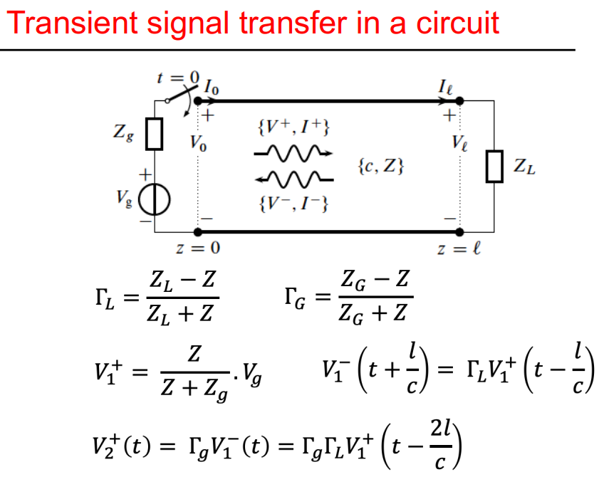
on the boundary of plane dielectric layers:
therefor:
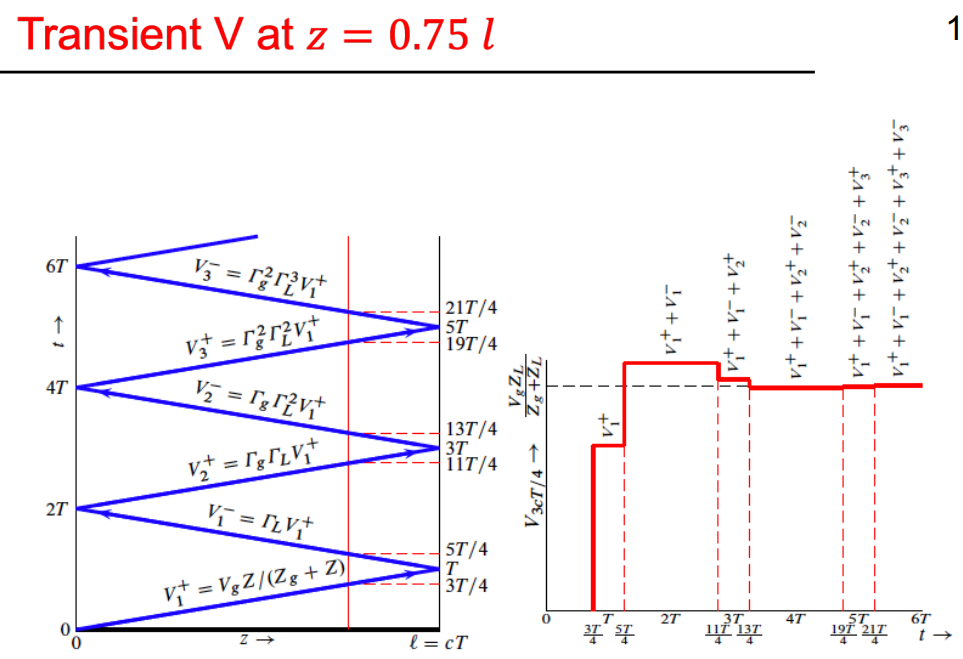
example:
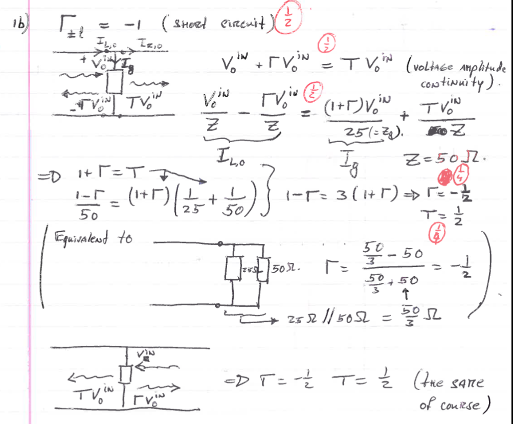
when its steady use load impedance since TL is short circuit:
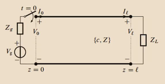
steady state no characteristic impedance, since no waves propagate. TL is short-circuited.
For circuit theory see exam question example in folder…
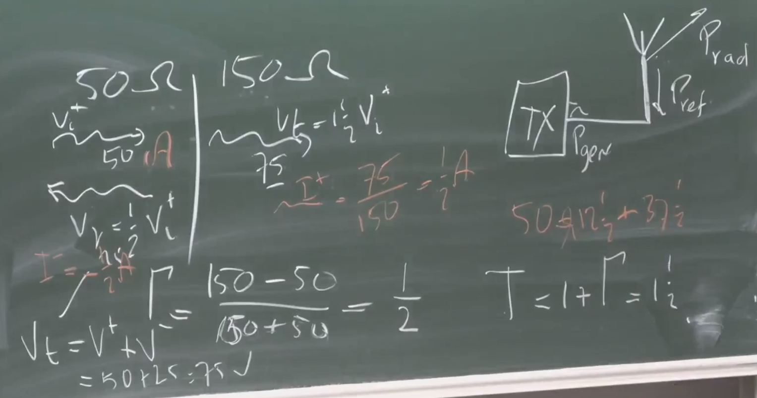
If there is complex load impedance there is phase and amplitude modulation of the reflected waves.
Transverse field vectors & Electromagnetic Power Balance
Poynting vector - YouTube
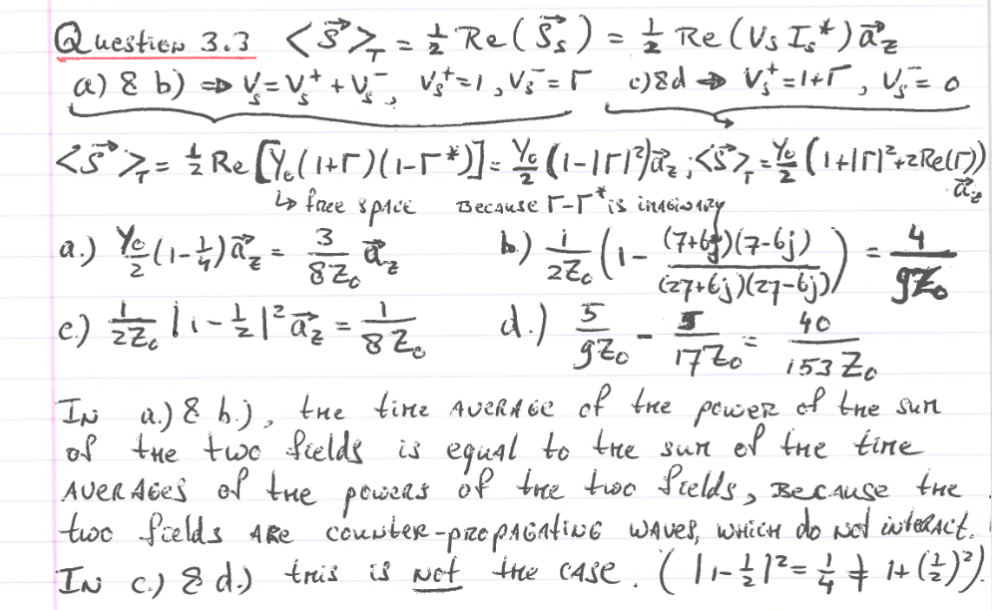
not useful to take a snapshot of poynting vector (relation of electromagnetic wave in time), thats why we usually find the average over time.
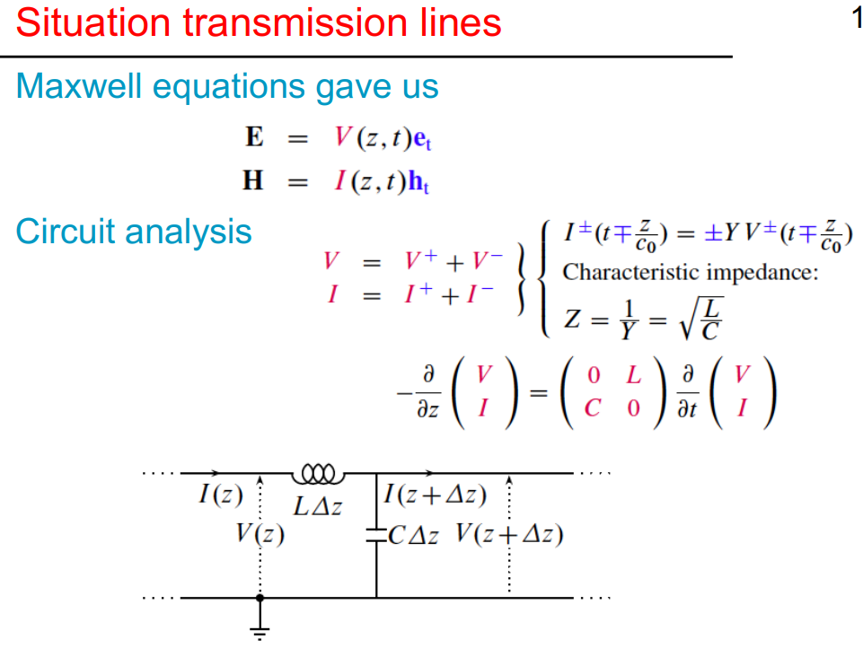
lumped elements represent transmission lines. not actual inductances/capacitances.
at least 2 conducts needed. (coaxial cable)
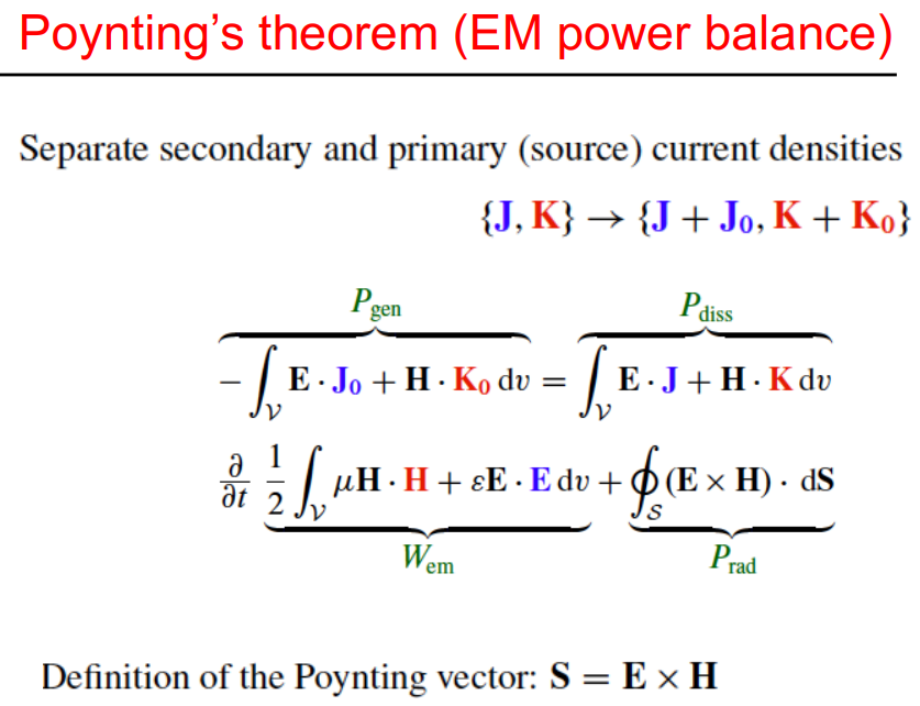
Poynting’s theorem
Poyting’s theorem: separate secondary and primary (source) current densities
maximize
extra
for transverse field: helmholz decomposition
laplace equation…
voltage and current normalization
for electromagnetic power balance:
!!! moment in time just after the switch has been activated, but before possible reflections from the end of the line have returned:
Time-harmonic waves
Summary
Detailed notes
now instead of
its
in a loss-less environment
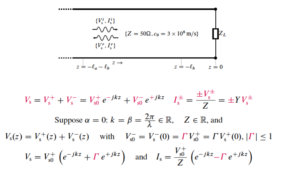
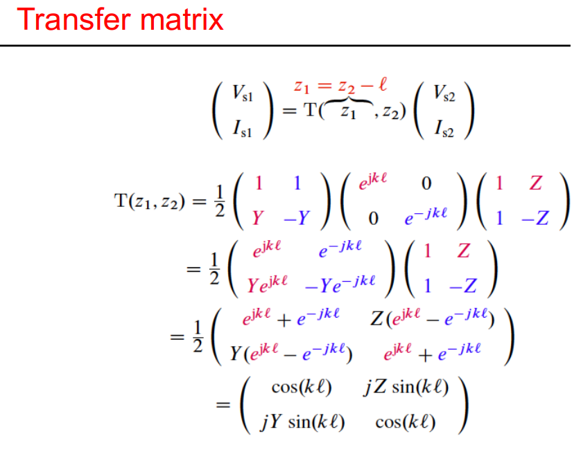
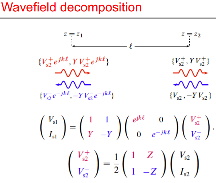
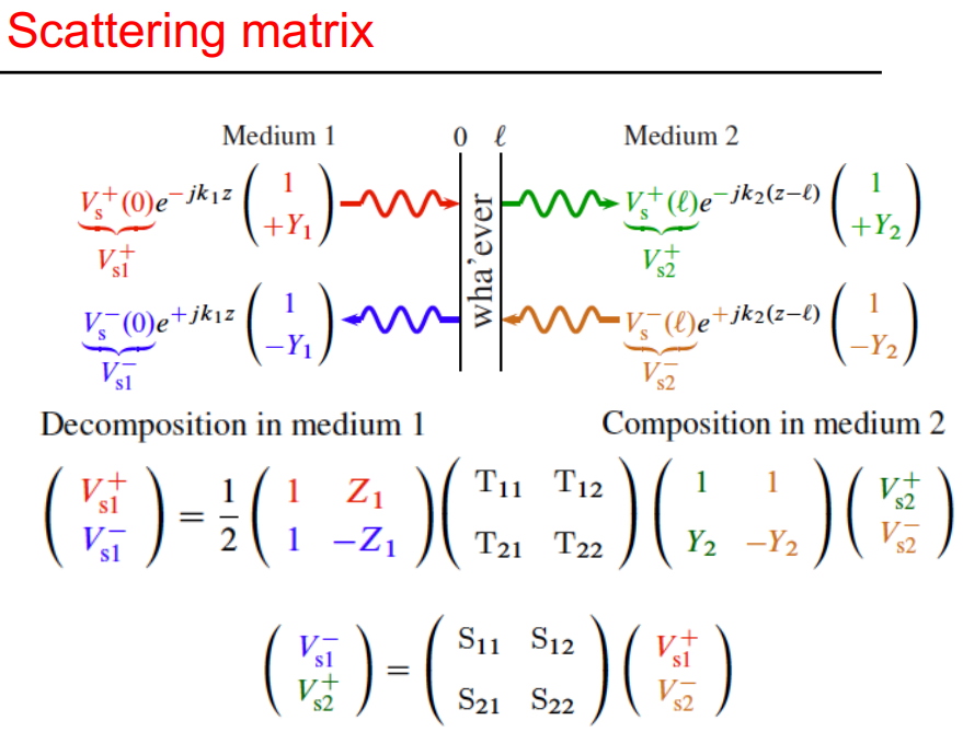
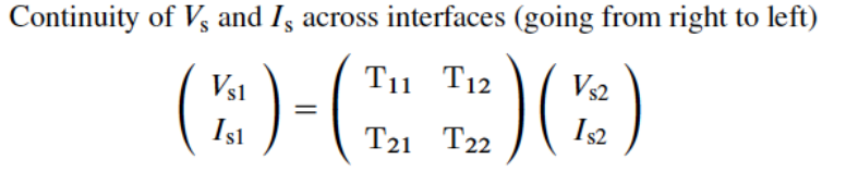
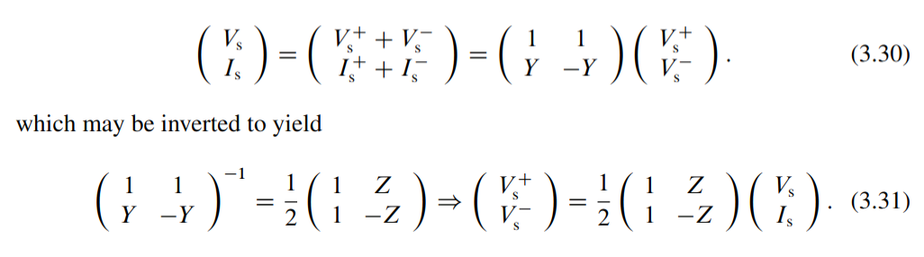
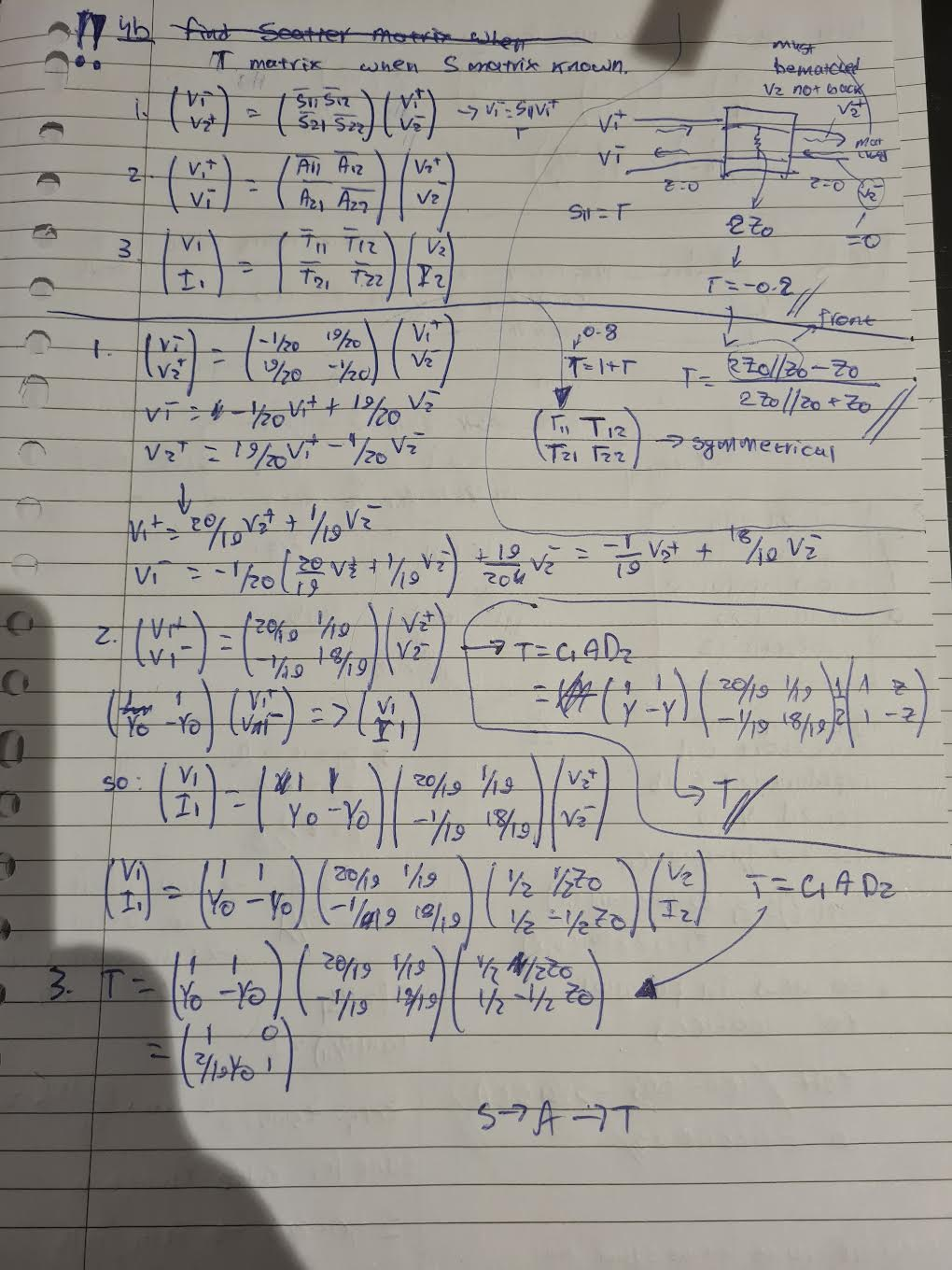
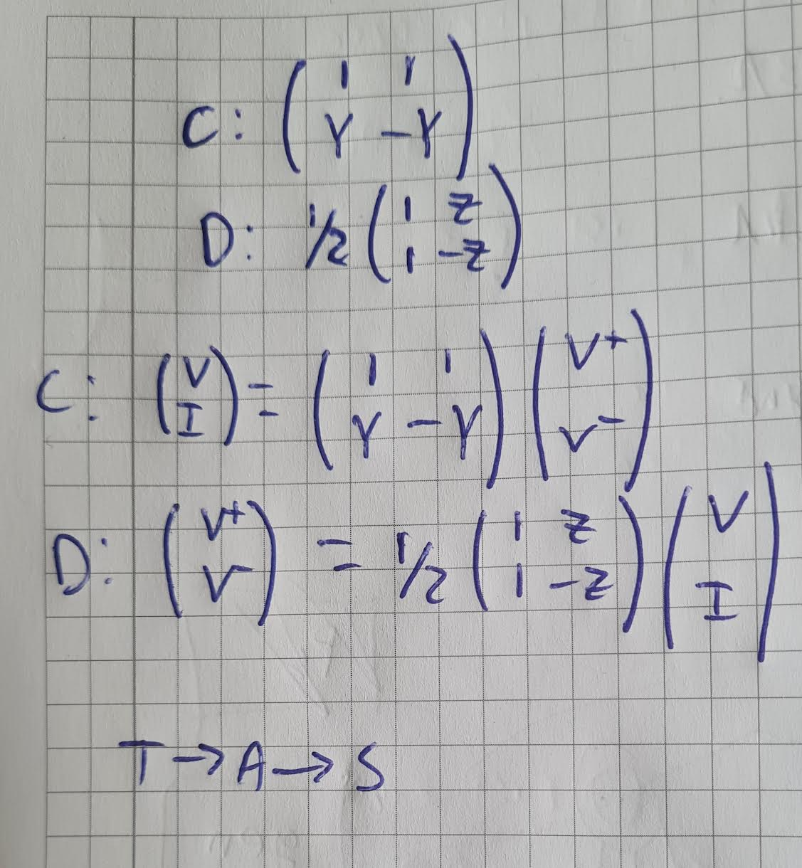
A-matrix the first one
A matrix is decomposition of medium 1 and composition of medium 2
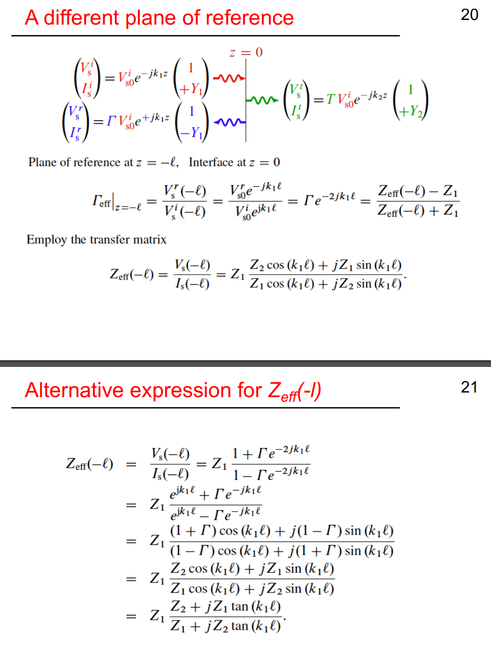

Power Calculation:
Scattering parameters - Wikipedia
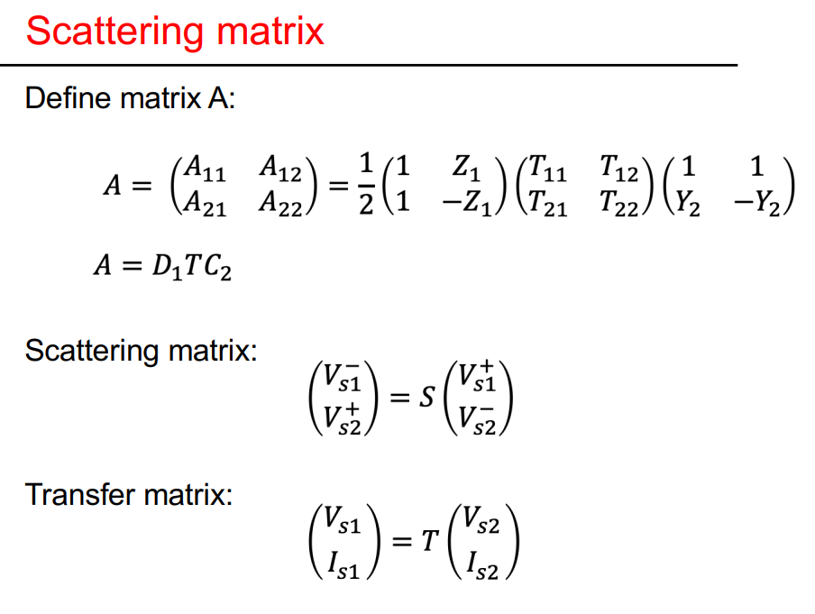
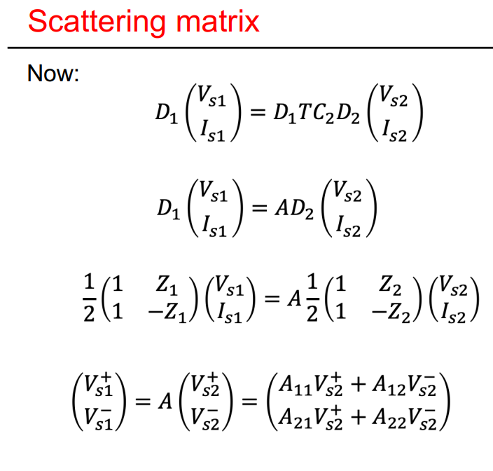
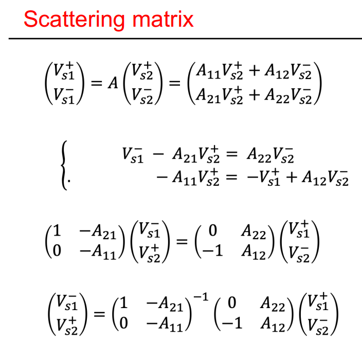
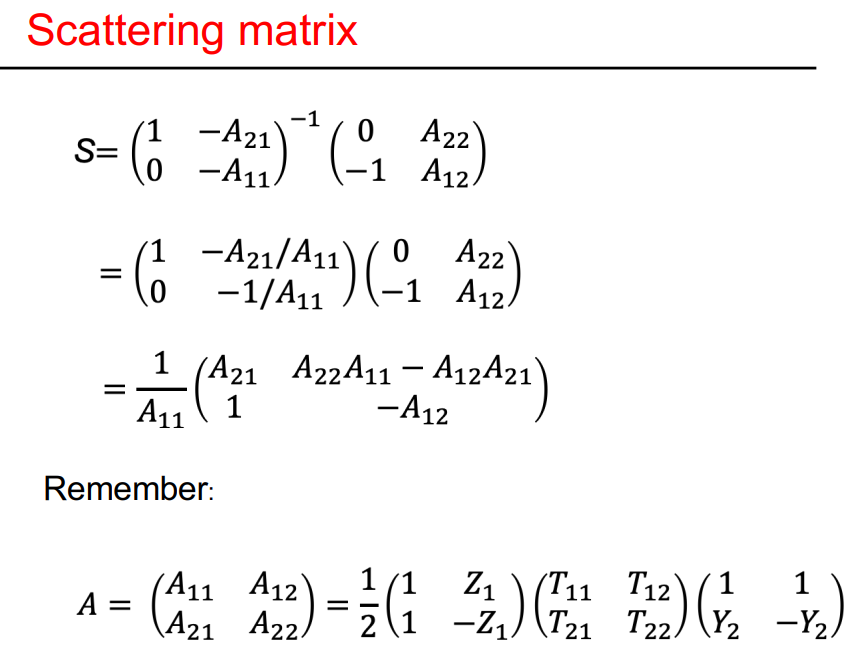
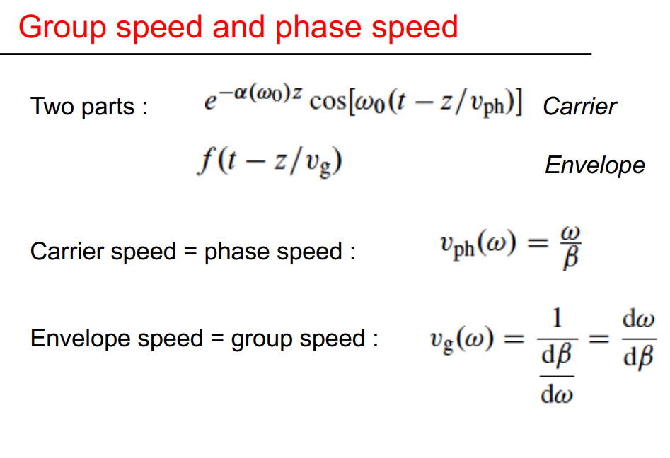
Scattering matrix, phase and group speed, dispersion
Topic: S-Parameters and Impedance Matching
Summary
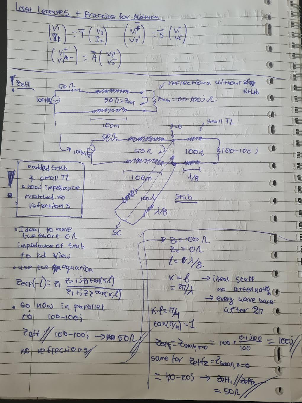
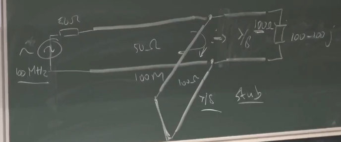
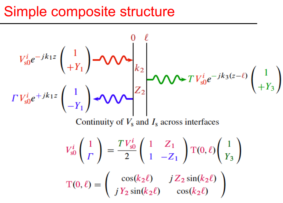
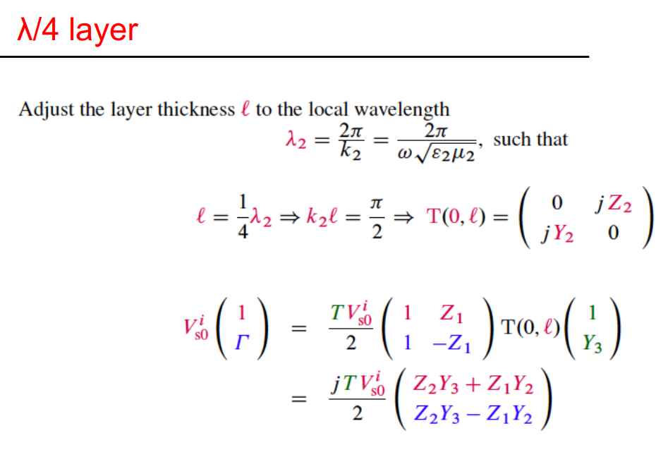
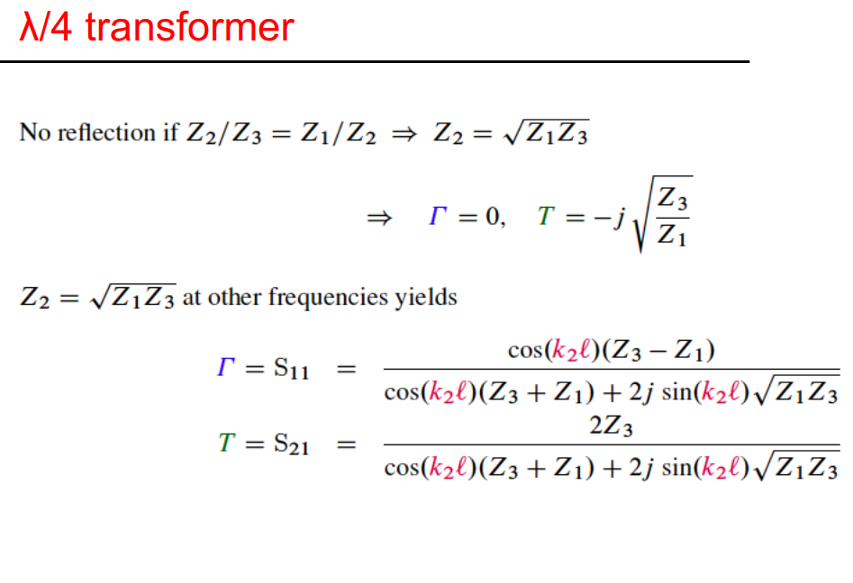
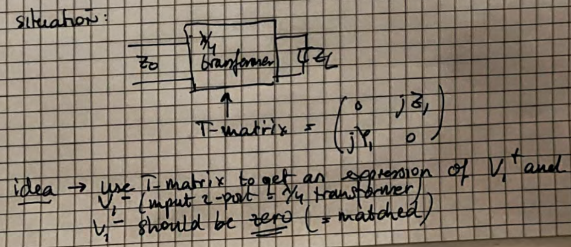
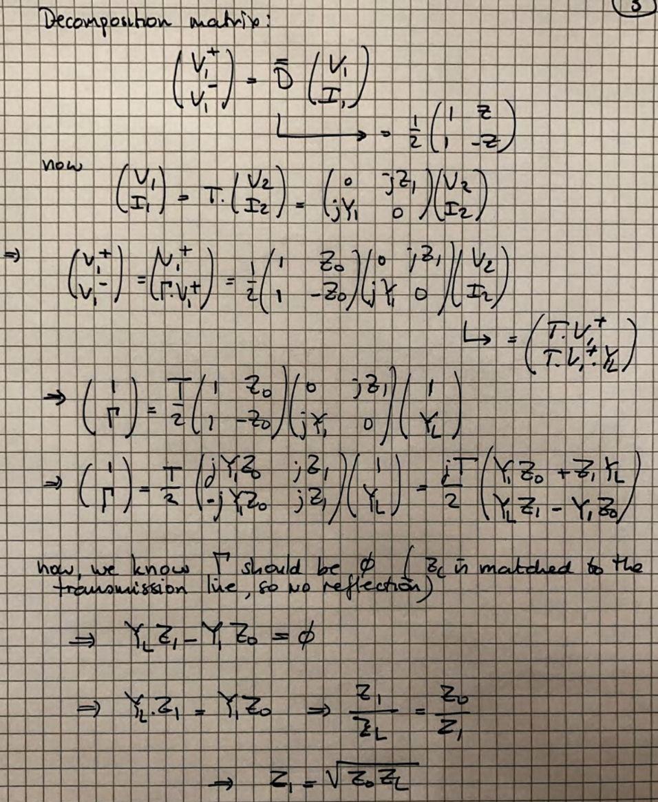
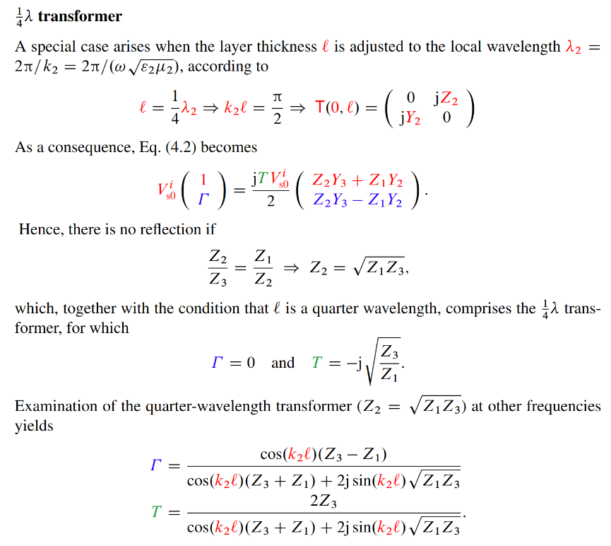
quarter-wavelength transformer optimal conditions:
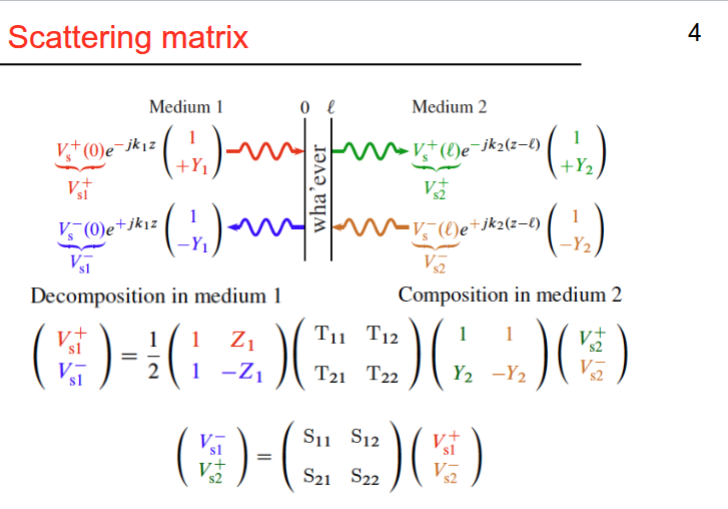
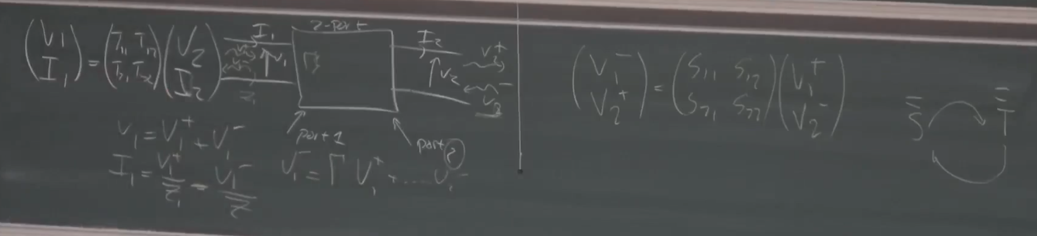
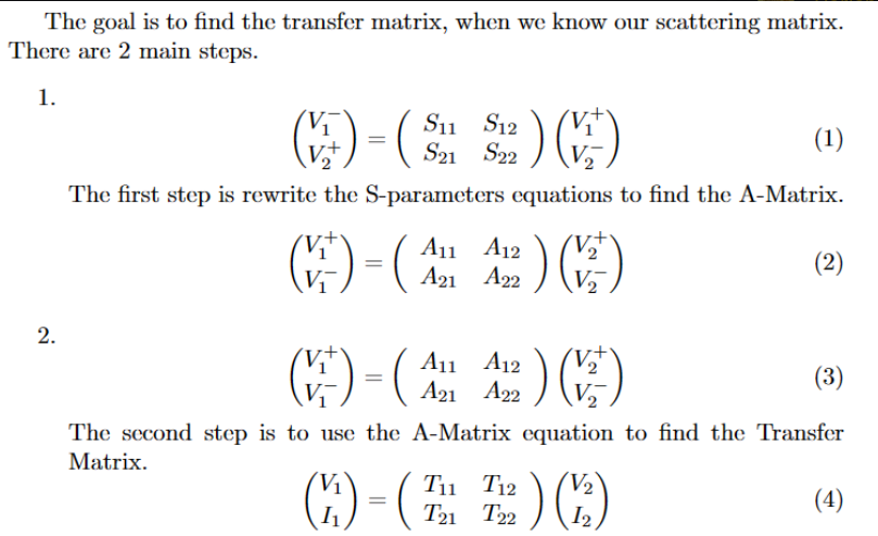
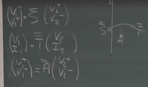
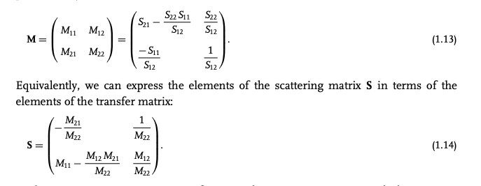
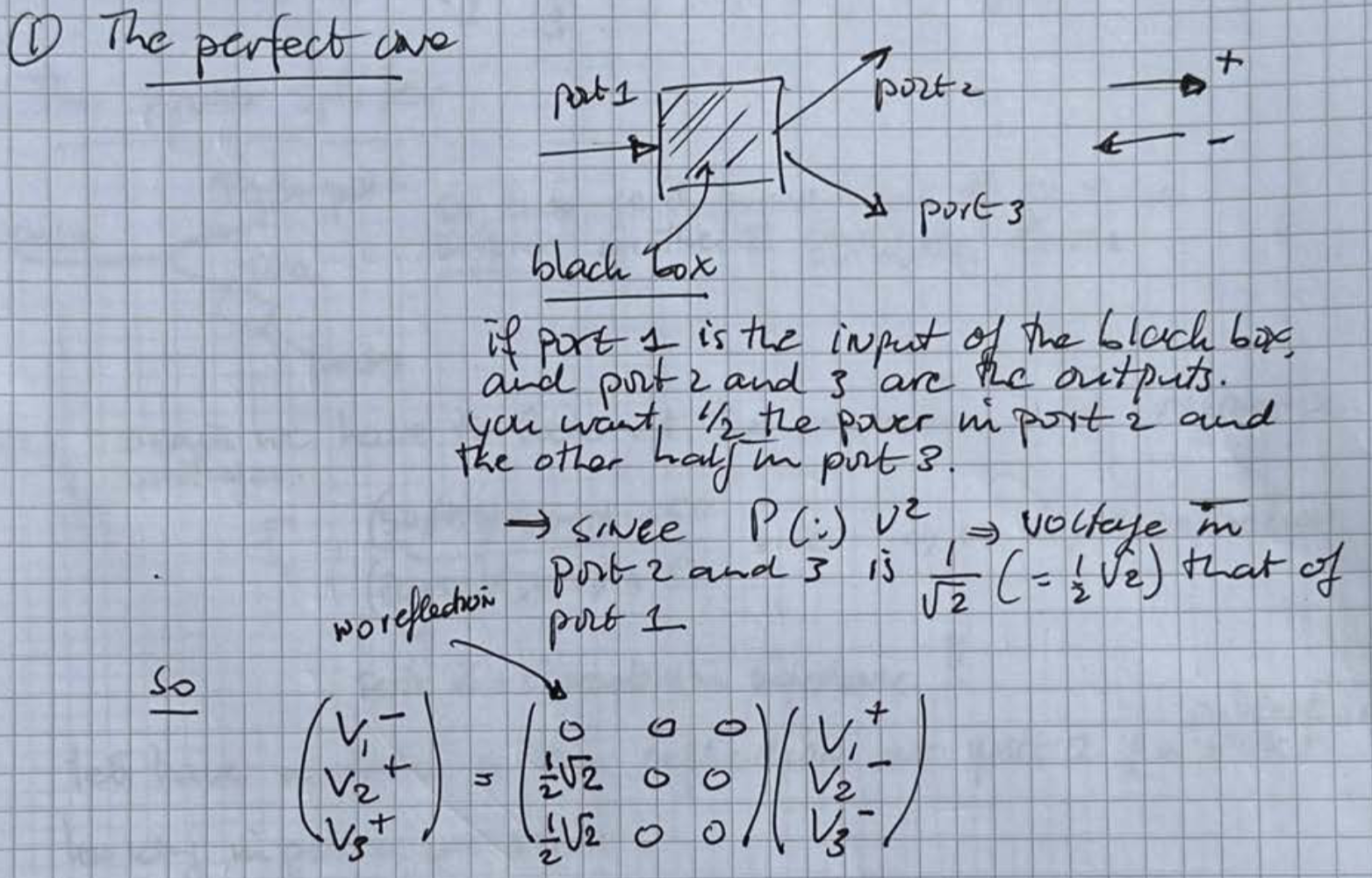
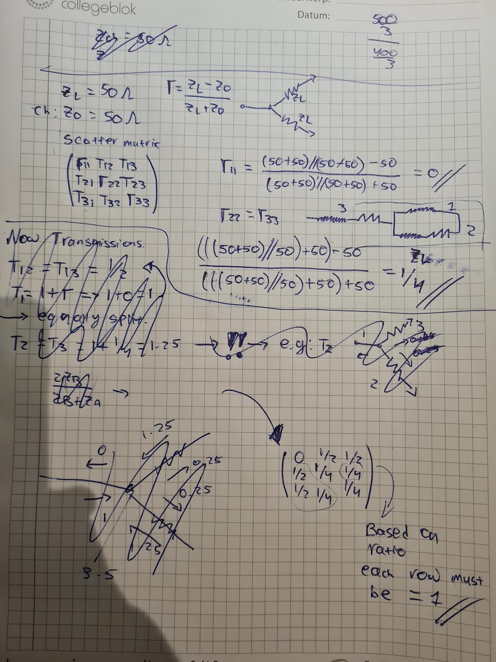
Scattering matrix or s-matrix descries how incoming waves are transformed into outgoing waves after interacting with a system.
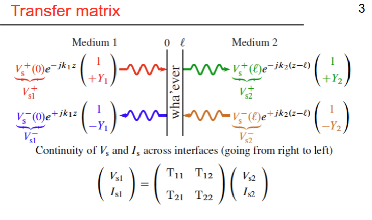
Transfer matrix or m-matrix relates waves amplitudes at different points within the system.
Detailed notes
only works for small bandwidth one frequency range. To match impedance.
PART 2
Plane waves in arbitrary directions - reflection and refraction at planar interfaces
Topic: Plane Waves and Reflection
slide info
Summary
wavenumber:
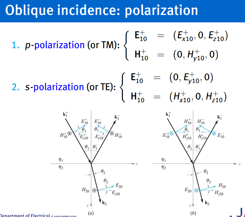
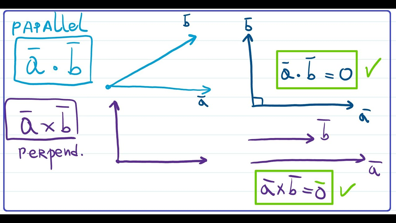
determine p or s polarization if p polarized then secondary conditions satisfied
if the the phase difference is not
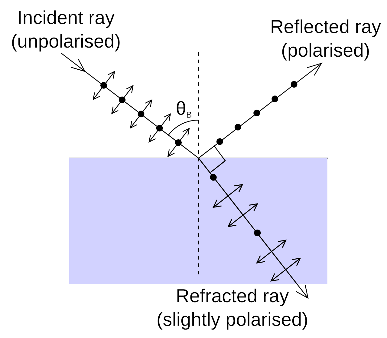
The brewster’s angle is the angle of incidence where light will be perfectly transmitted through a surface with no reflection. The critical angle of internal reflection is when a wave is completely reflected 100% at a certain angle.
reflection and transmission coefficients:
s-polarized
p-polarization:
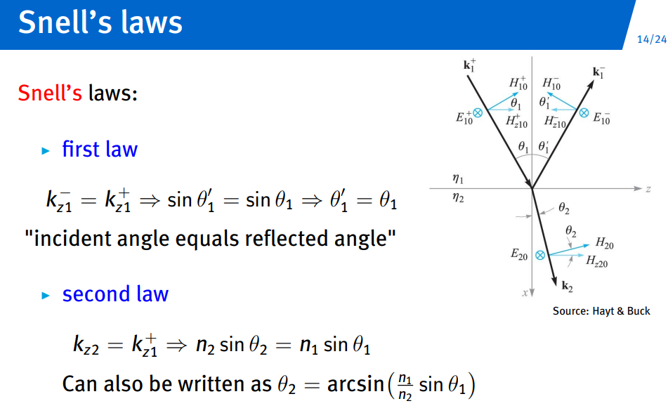
snells law:
Plane Waves II
other
Wavenumber - Wikipedia
wavenumber, refers to the spatial frequency of a wave over a specific unit distance.
A wave number is related to but different from frequency, which is temporal in nature.
Elementary plane wave (EPW): General Solution:
wave number:
wave impedance:
dispersion diagram but here we only use the real propagation coefficient so
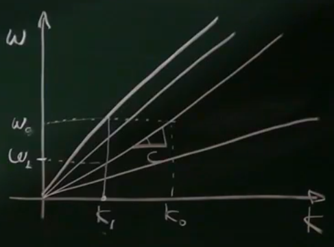
three types of waves:
the wave number
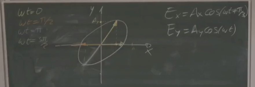
wave polarization:
- Wave polarization: time-dependent orientation of the E-field vector at a fixed point in space.
- For instance, in case of a travelling wave in the (depends on direction)
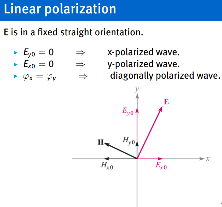
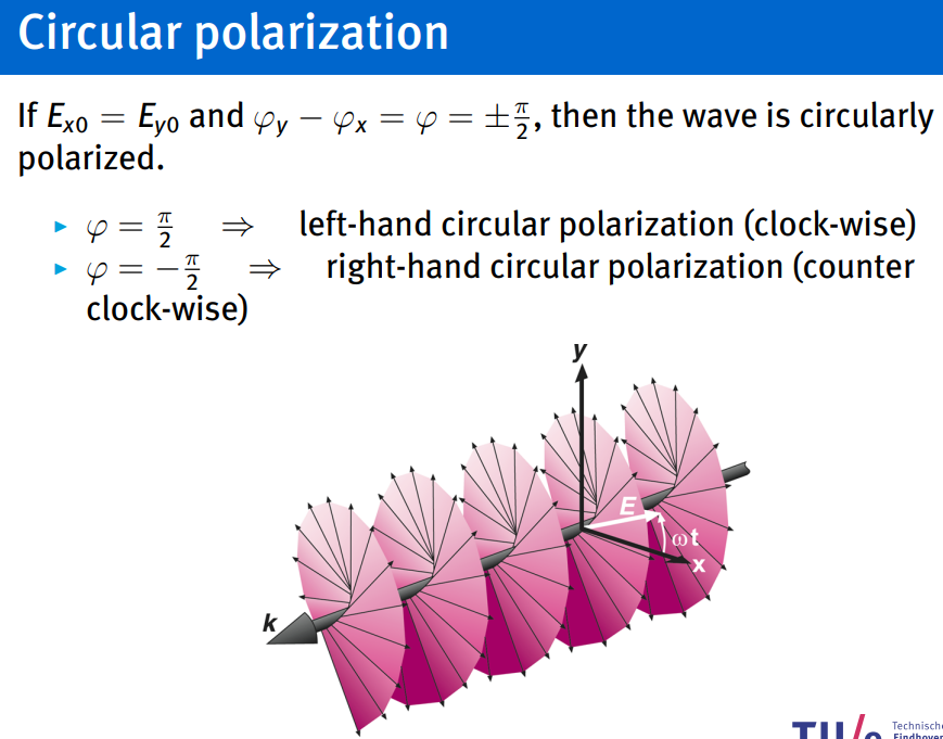
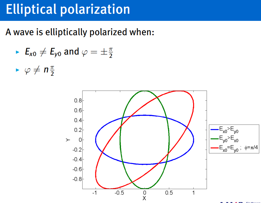
if the the phase difference is not
what is plane in a plane wave: surface of constant amplitude, surface of constant phase… (for most common plane waves these 2 are the same plane).
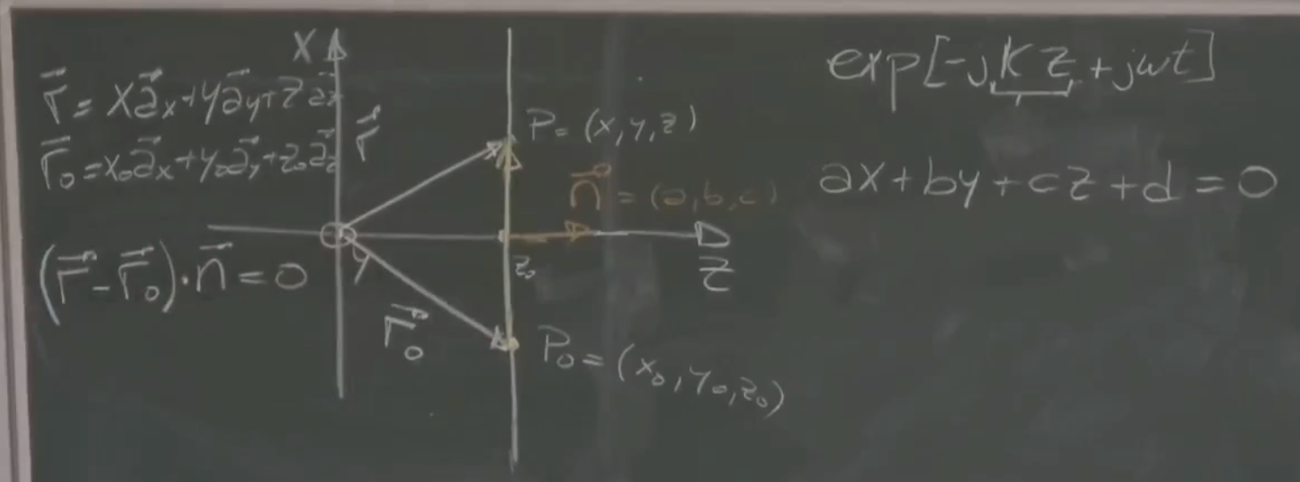
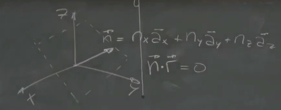
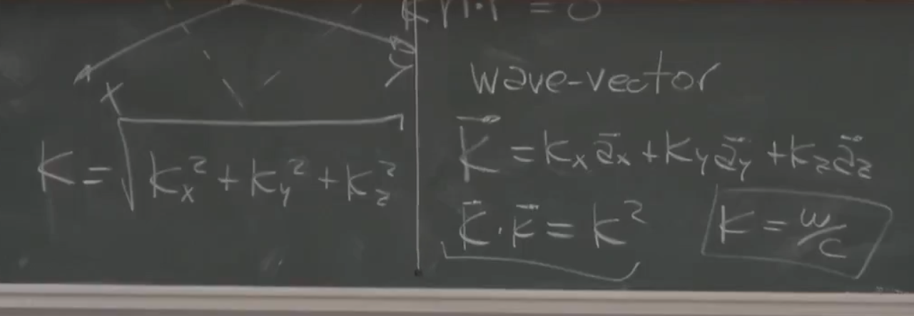
plane waves in arbitrary directions:
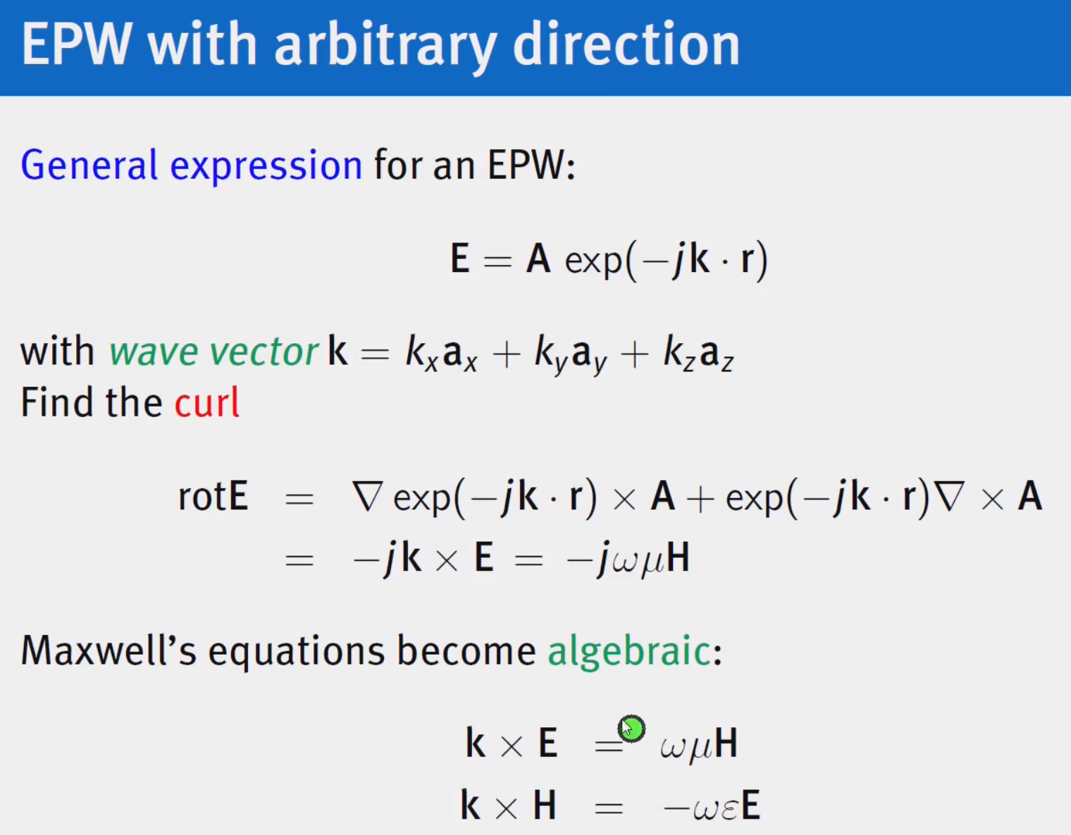
EPW with arbitrary direction:
!!! WAVE VECTOR AND WAVENUMBER DIFFERENT
EPW: conditions for A and k
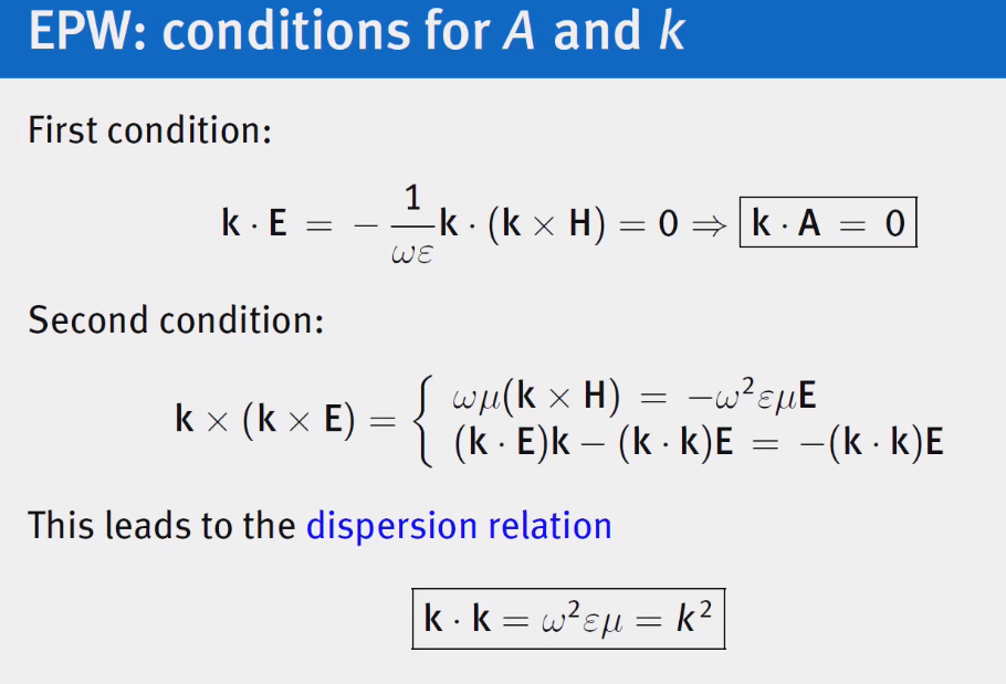
for the 2nd one in the array this identity was used:
Converting From E to H
Based on format: **
Reflection and Refraction
Topic: Plane Waves and Reflection
only flat discontinuity is considered…
boundary conditions essential… are solutions to integral form Maxwell equations
Boundary Conditions:
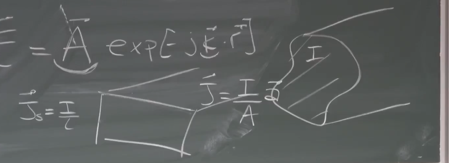
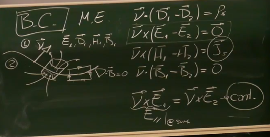
- only tangential component of electric field at the surface…
- while magnetic tangential field can be discontinuous as it can induce current at the surface which compensates for it…
- normal of electric field can be discontinuous as charges that accumulate at the surface can compensate for it…
- while normal for the magnetic field is continuous: magnetic field in = magnetic field out… one of the Maxwell definitions…
- for BC keep in mind sign change based on how you choose normal…
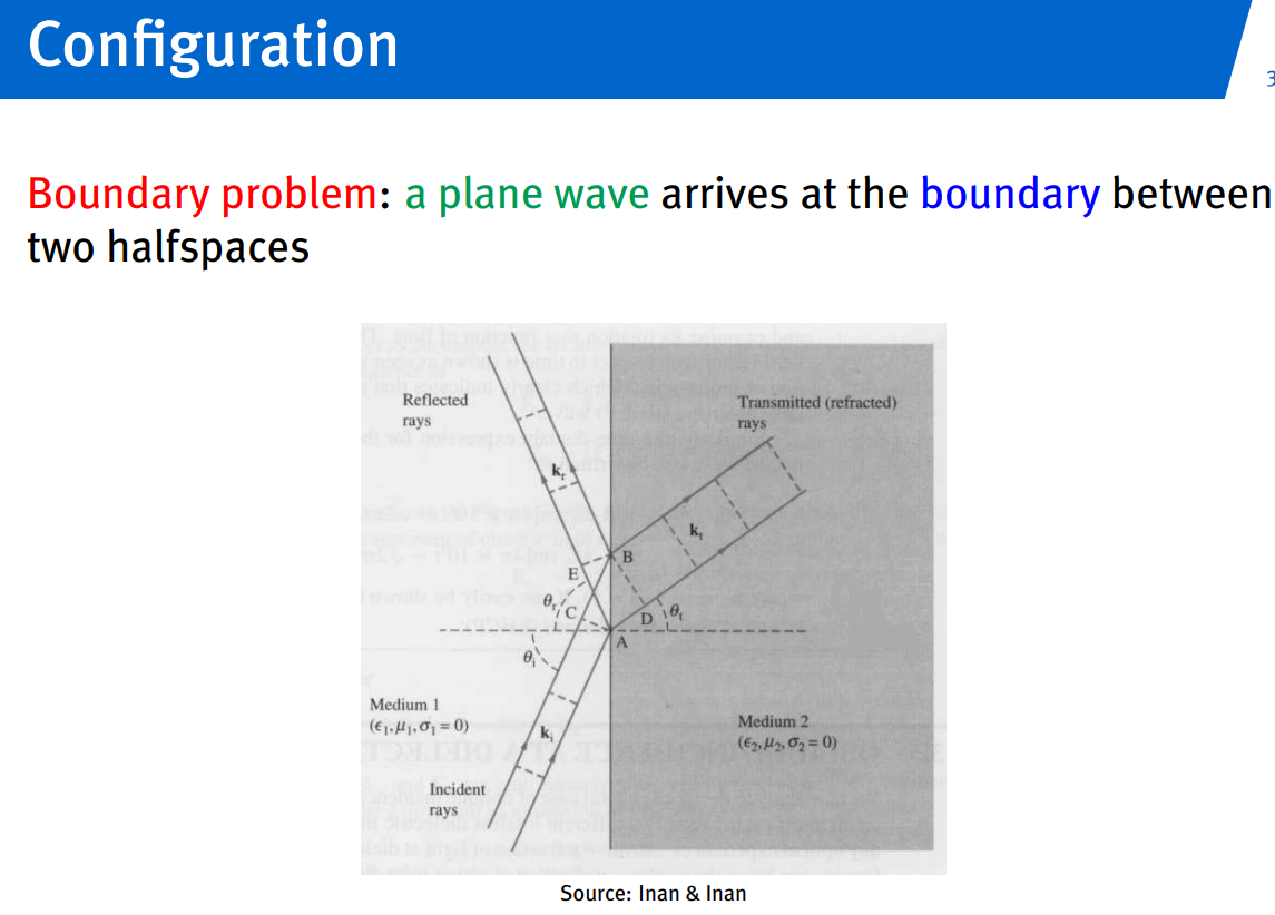
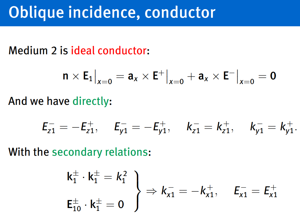
oblique incidence medium 1:
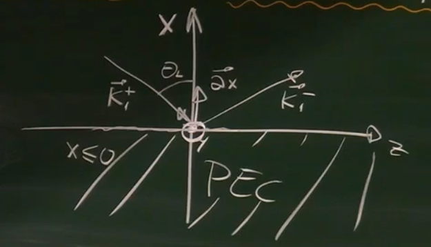
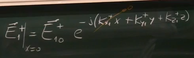
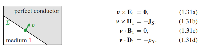
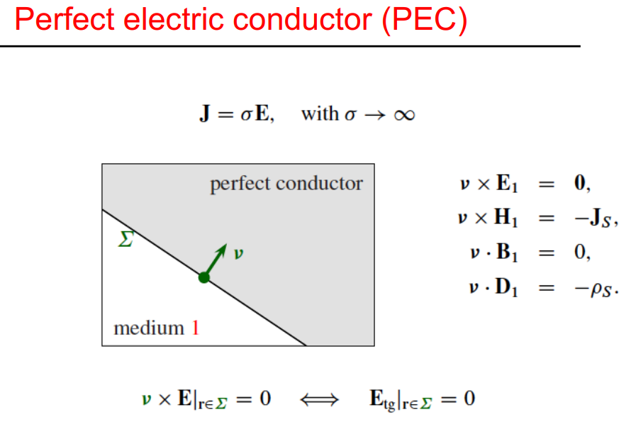
- no fields in PEC(metallic surface)…
- tangential components near metals vanish…
- the reason we dont use the 2 boundary condition which equal
is because we dont know those components on PEC… - For
component since its normal to surface compared to its conditions are the opposite… - normal component of wave vector reflects (not tangential), tangential component of electric field reflects not the normal one…
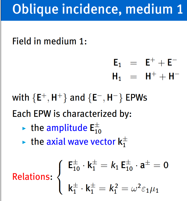
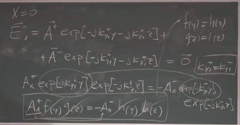
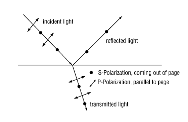
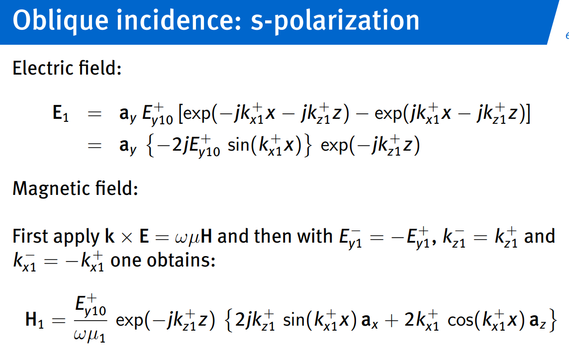
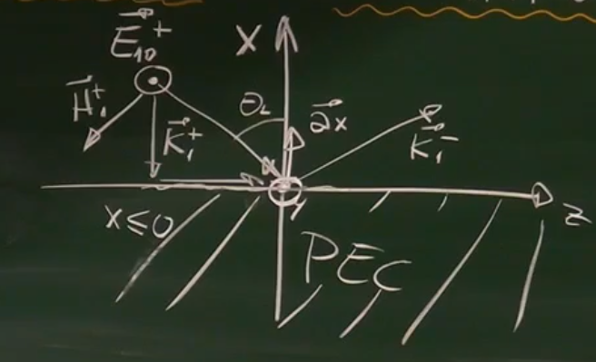
for H think of right hand rule: middle: k, thumb: E, pointing: H
Deriving Polar Formulas
: Euler Formula
for sine:
for cosine:
- standing waves are obtained by superposition of plane waves when they are in certain shape…
- fourth type of wave:
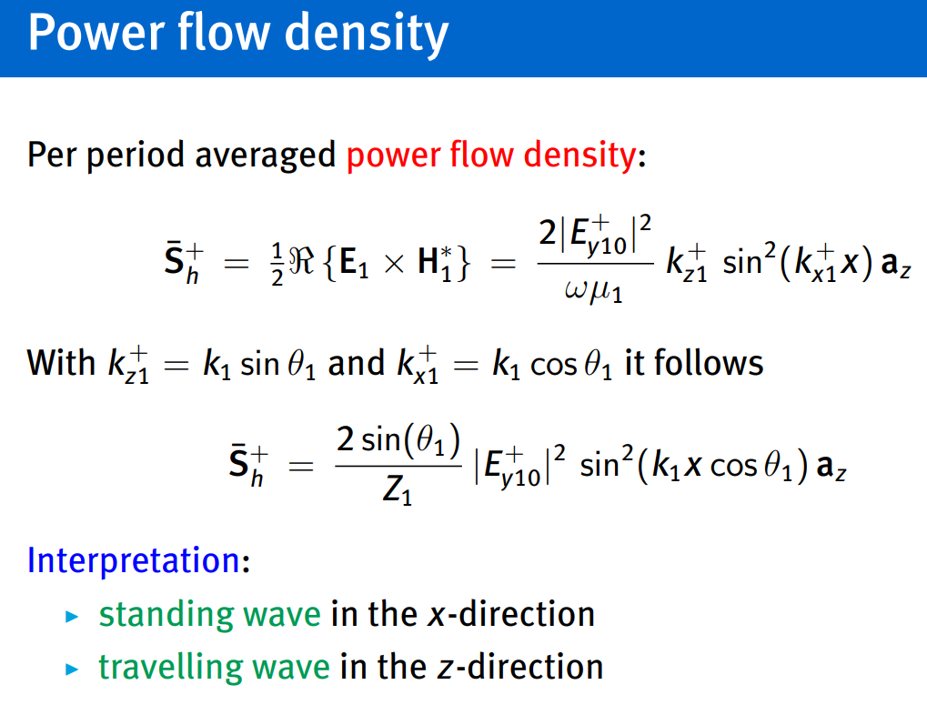
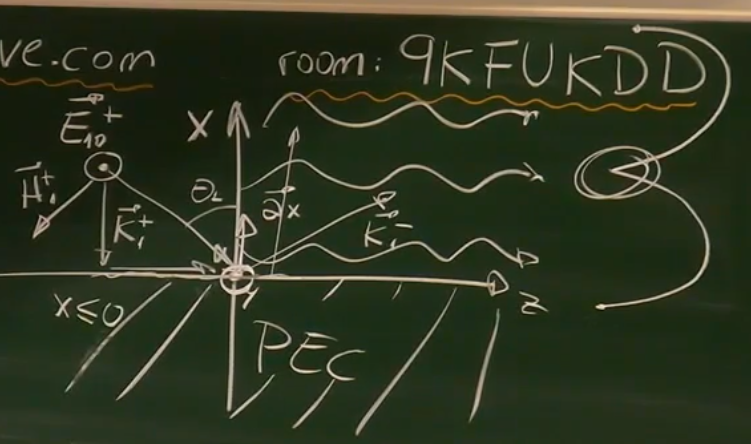
- traveling power wave everywhere in the x direction…
- at boundary power is 0 then it grows and then again 0
- the circled thing is distructive interference example if you are near car that could impact your fm radio…
Wave guide: Conducting plates at
Additional boundary condition:
this requires:
Waveguide - Wikipedia
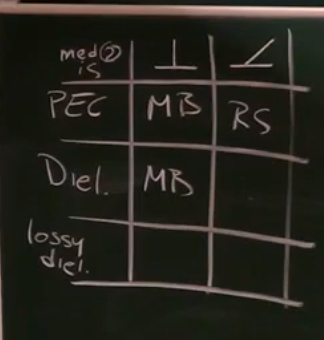
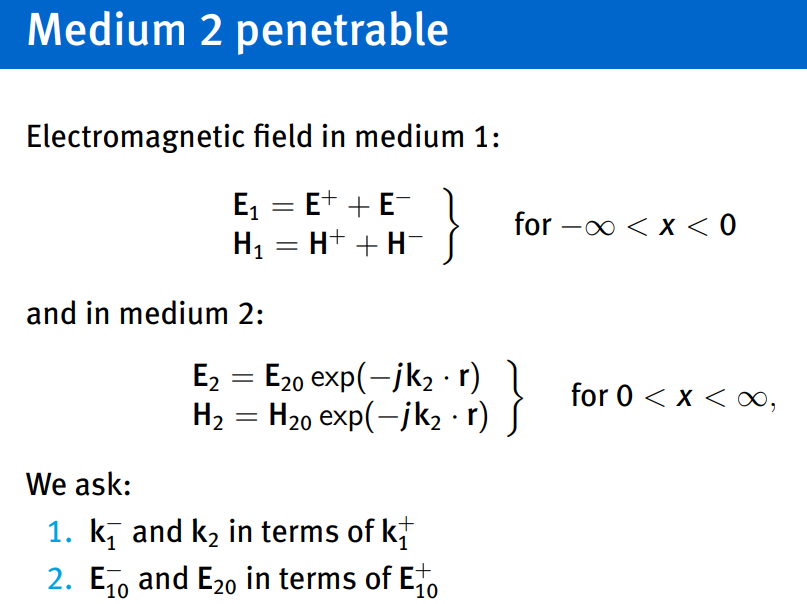
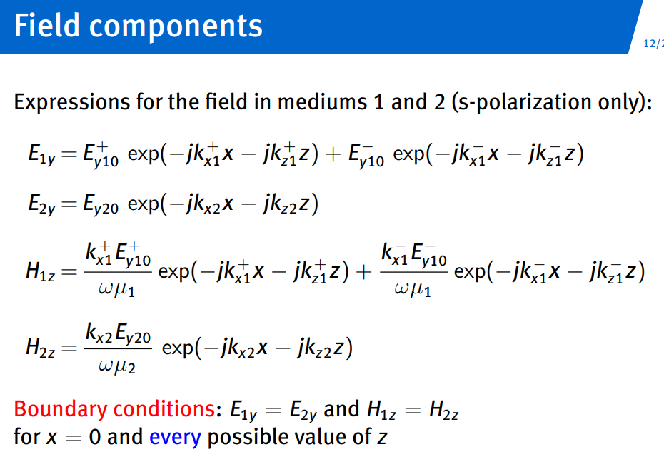
- p polarized(right diagram) E field parallel to plane of incidents, while s(right diagram) is perpendicular
- x component vanishses in field component since itsn ormal to the surface and equal 0 when we apply boundary conditions…
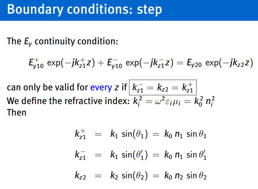
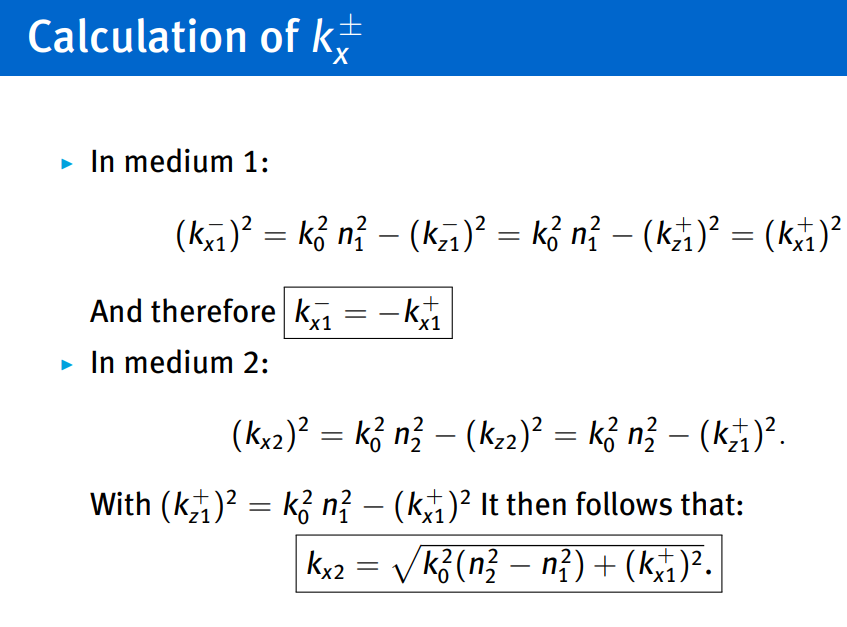
- z component only at surface continuous…
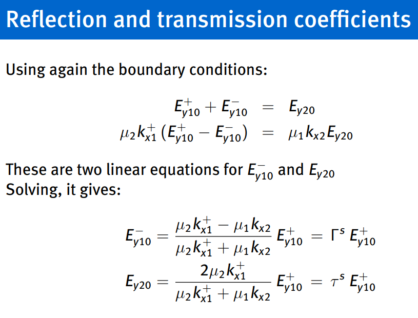
reflection and transmission coefficients:
s-polarization:
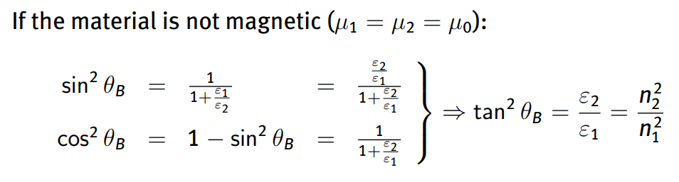
if both mediums are dielectric materials (
we use
p-polarization:
by exchanging
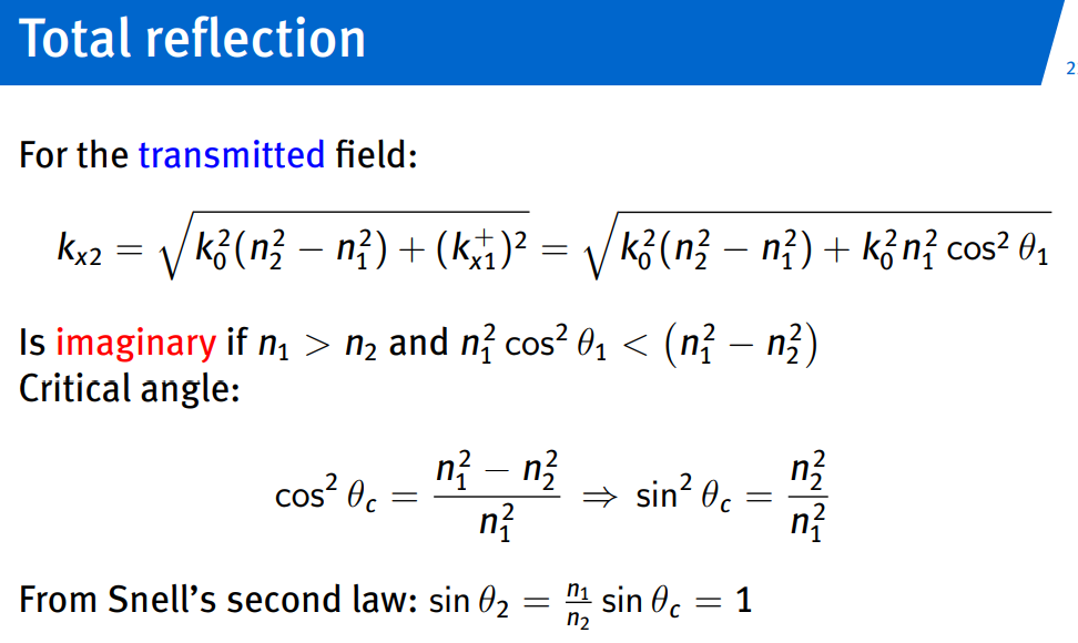
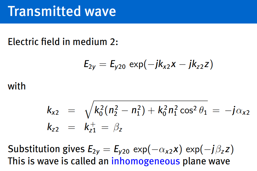
Brewster angle and Critical angle
Physics 53 Polarization (5 of 5) Brewster’s Angle - YouTube
Substitution leads to a linear equation for
Solving the equation, it gives:
5.
Guided waves
Topic: Waveguides
Summary
Resonant Cavities
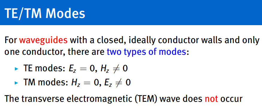
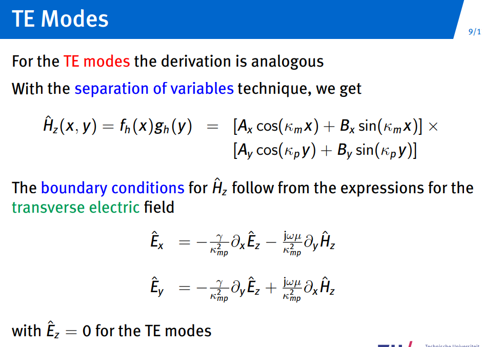
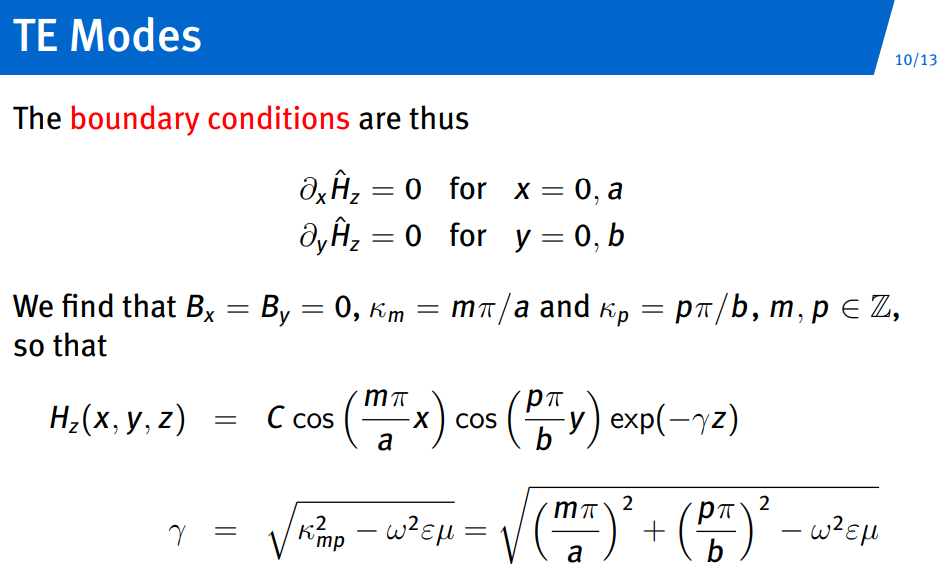
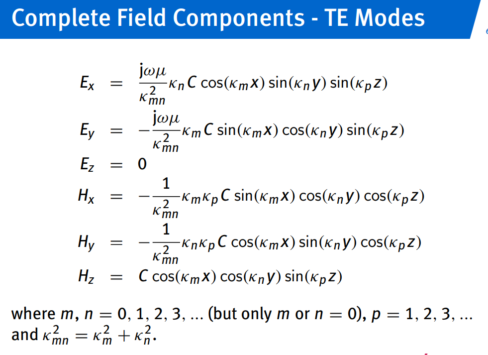
- TE Modes:
- Fundamental equation:
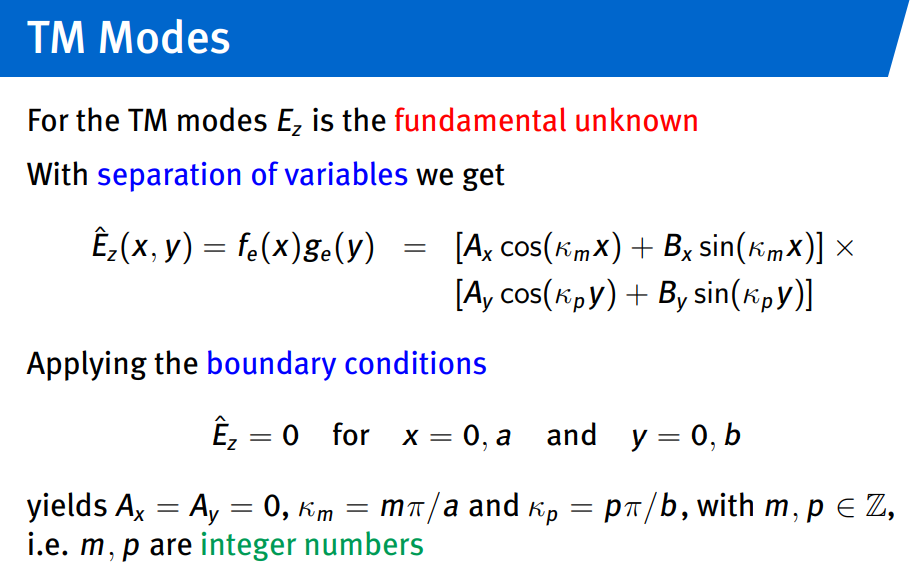
IF TM - Solution with boundary conditions:
- Cutoff frequencies:
cutoff frequency, corner frequency, or break frequency is a boundary in a system’s frequency response at which energy flowing through the system begins to be reduced (attenuated or reflected) rather than passing through.
n=2 means two half-wavelengths fit along the y-axis.
- Fundamental equation:
The indices m, n, and p in the context of resonant cavities represent the mode numbers, which correspond to the number of half-wavelengths of the standing wave pattern along each of the three spatial dimensions (x, y, and z) inside the cavity.
Dielectric Slab Waveguides
-
Waveguide Structure:
- For
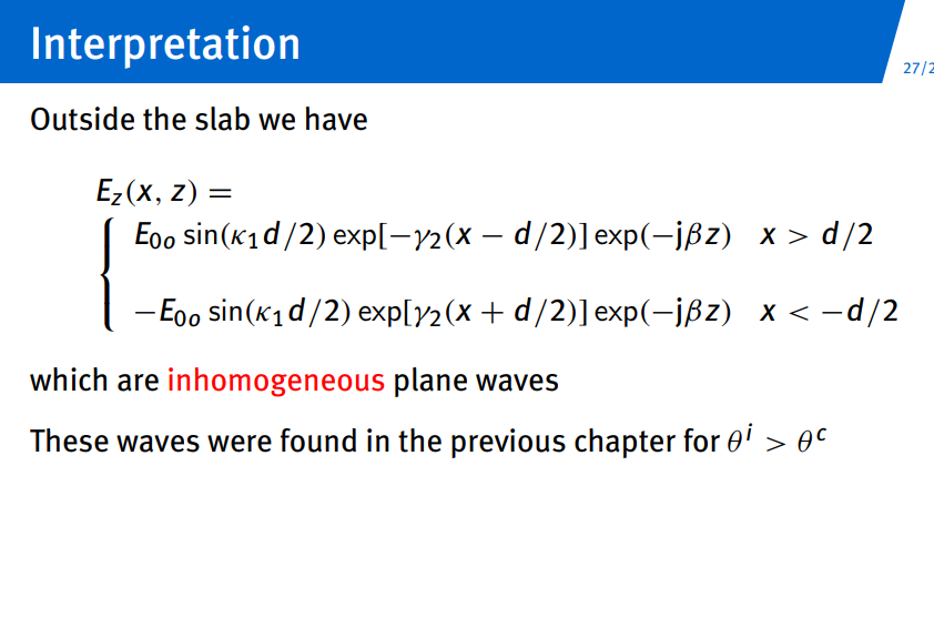
, Total Internal Reflection (TIR) occurs. - Fields in each region:
- For
-
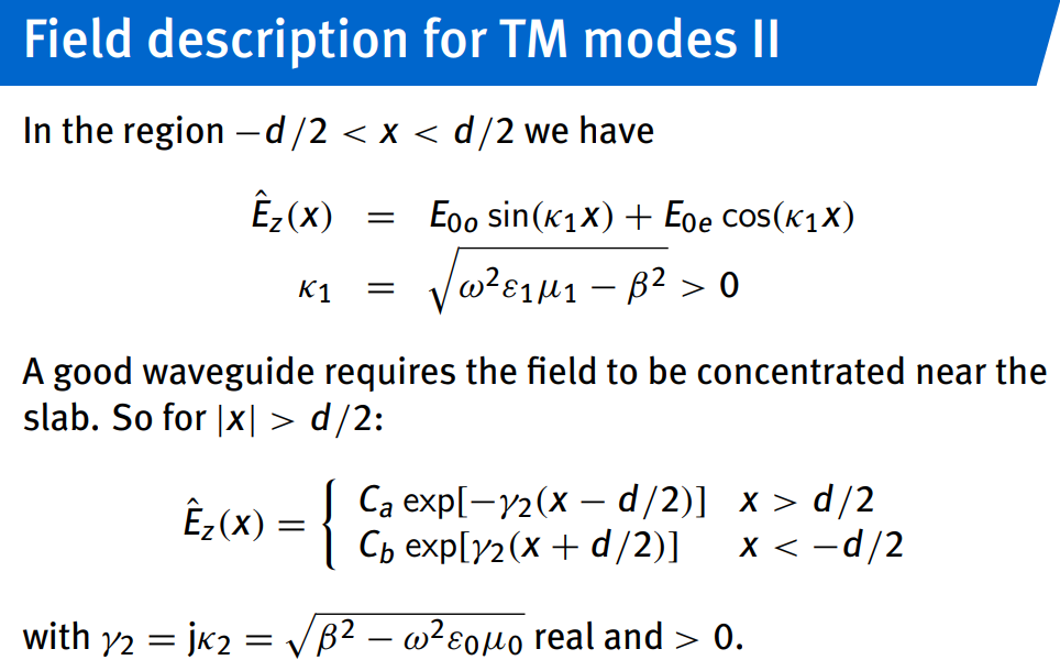
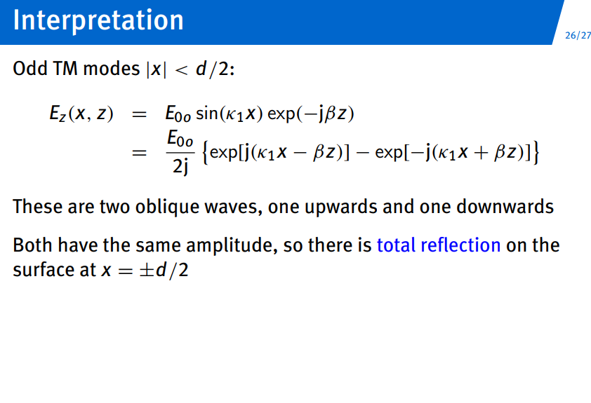
TM Modes:
- Inside the slab:
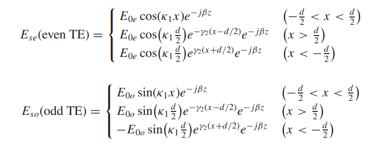
- ODD modes:
- EVEN modes:
- Inside the slab:
-
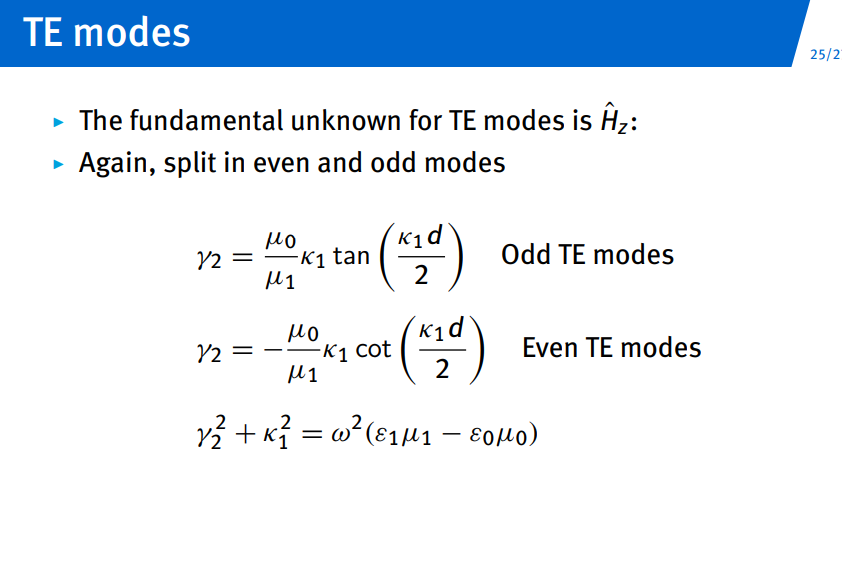
TE Mode Summary:
- Similar expressions for TE modes can be derived by replacing
with and adjusting boundary conditions.
- Similar expressions for TE modes can be derived by replacing
-
Key Relationships:
- Evanescent field decay constant:
- Phase condition for modes:
- Single mode condition:
- Evanescent field decay constant:
Parallel-Plate Waveguide
Topic: Waveguides
Waveguides Explained - YouTube
Slab Waveguide Explained - YouTube
Origin of TE and TM Modes - YouTube
-
ampere, faraday law,
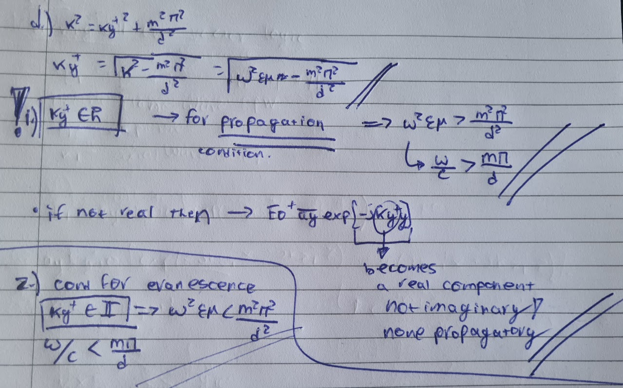
must be imaginary otherwise wave decays wont work. -
-
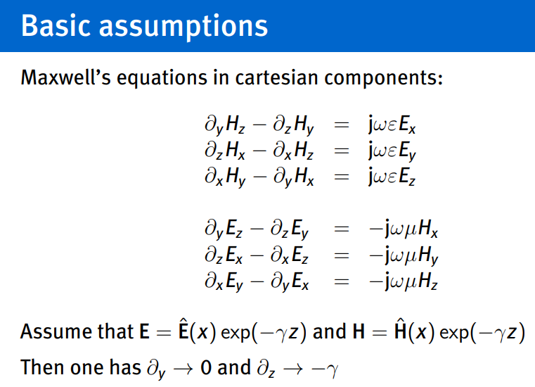
-
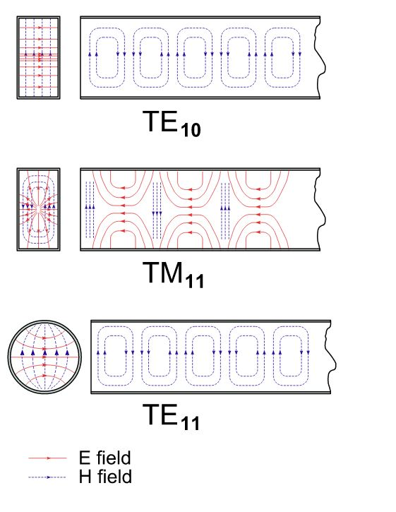
polarisation in terms of wave guides
-
fundamental unknwon: able to find all other of the total 6 components
-
-
-
-
-
-
-
Since TE waves…
-
-
-
decoupling:
-
-
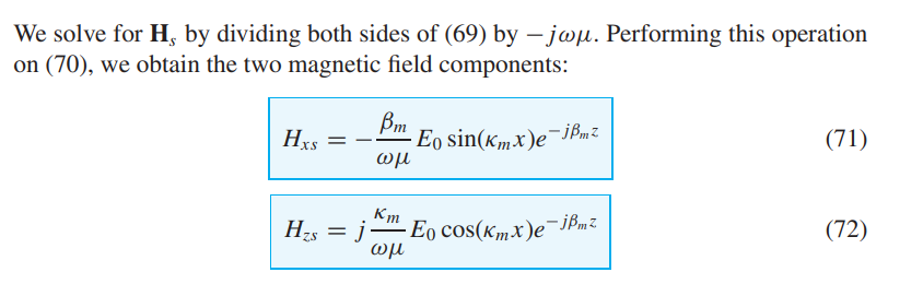
-
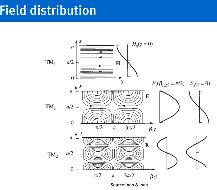
TM Waves:
-
-
-
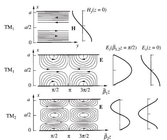
-
TEM Waves:
-
-
-
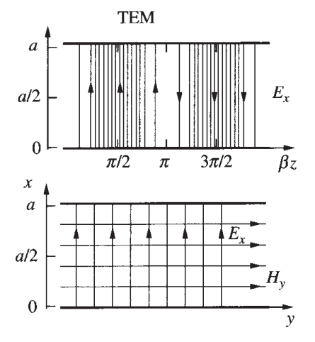
Rectangular Waveguides
Topic: Waveguides
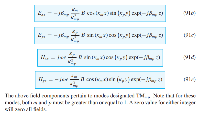
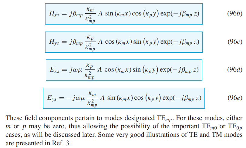
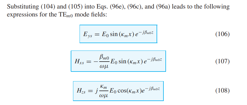
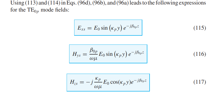
- The rectangular guide will support the TE and TM modes, but it will not support a TEM mode.
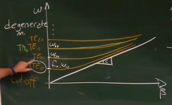
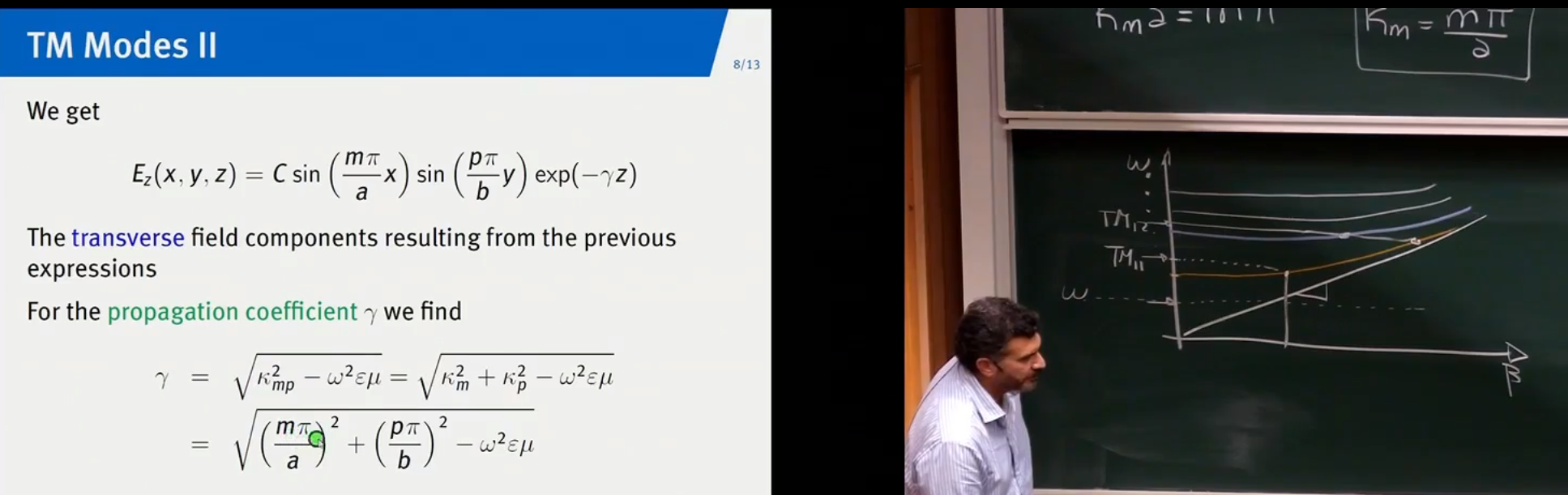
- so the graph
- before only plates on top bottoms, now on left and right…
- certain combination of
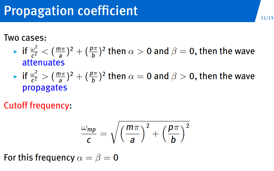
there is a certain frequency ( )…
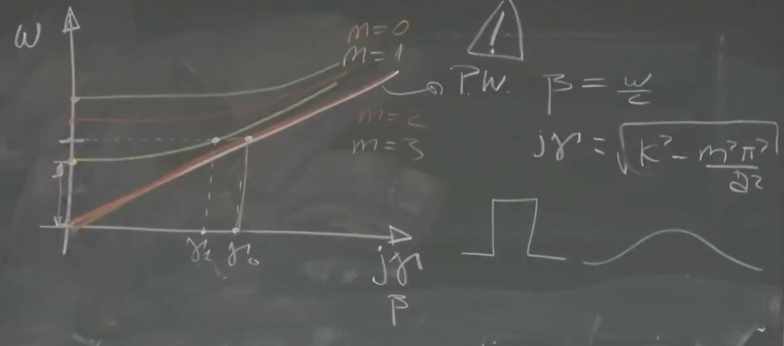
- when TE/TM have same cutoff frequency: degenerate mode
- must exceed
to achieve real value for so mp propagates… - cutoff for both is same frequency and wavelength…
Resonant Cavities and Dielectric Slab Waveguides
- for decoupling, only cavity formulas given (closed book) look and remember how those equations for parallel and rectangular those look like…
- Evanescent field - Wikipedia
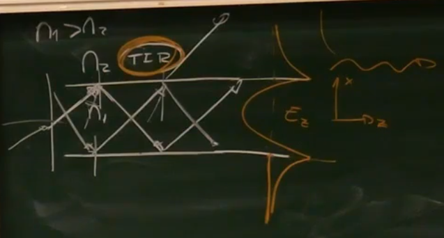
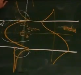
- so modes of TE, TM also split into (odd/even)
- standing wave inside, and 2 evanescent waves outside
Resonant Cavities
fully enclosed space… producing standing waves inside… no direction of propagation
even though now no propagation in (z) we still state it (standard).
Dielectric Slab
- not using metal but plastic, with
- assume no
dependence for each homogeneous region :
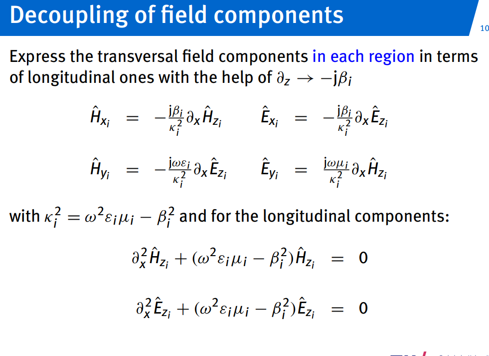
for outside
solutions expressed in TM/TE modes below is analysis for TM:
where
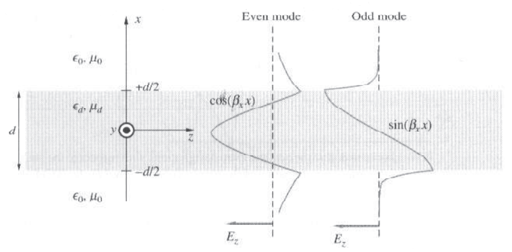
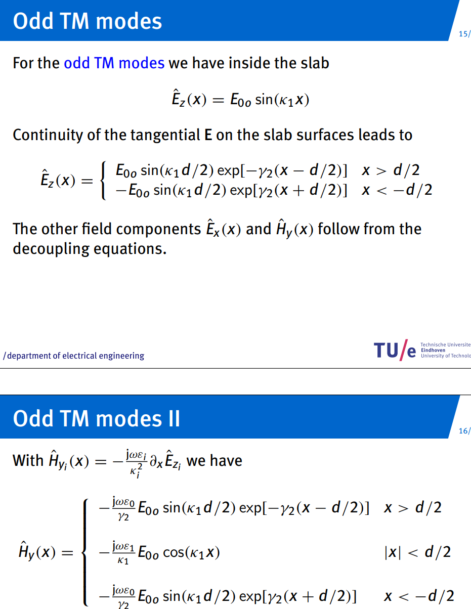
ODD
EVEN
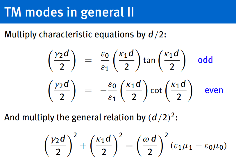
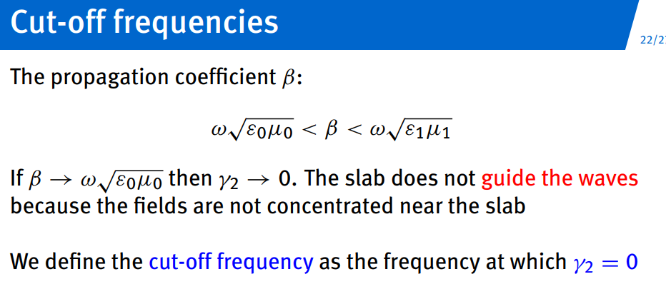
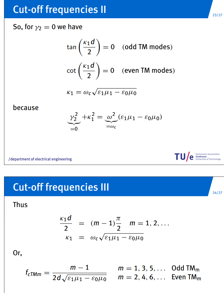
FINALLY FOR TE MODE SIMILAR:
Radiation
Topic: Antennas and Radiation
Summary
see behavior of far field and how dipole electric properties behave (
The Electric Point Dipole
Topic: Antennas and Radiation
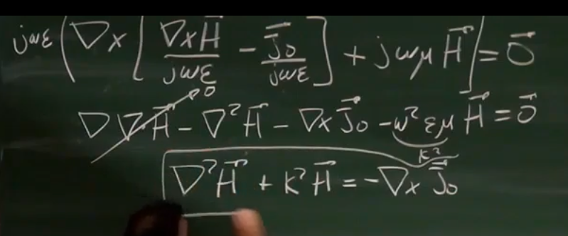
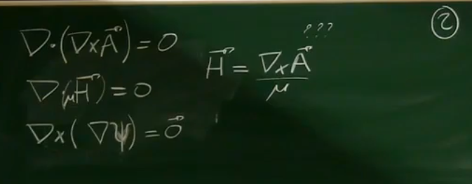
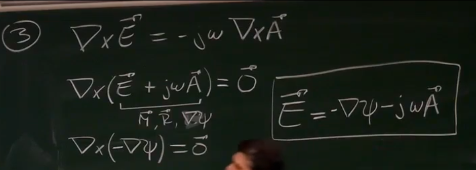
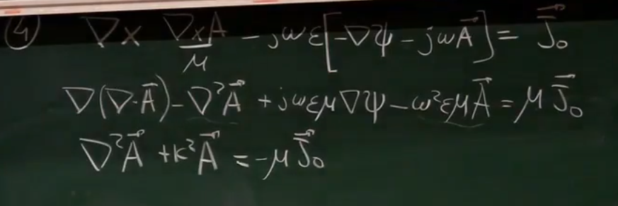
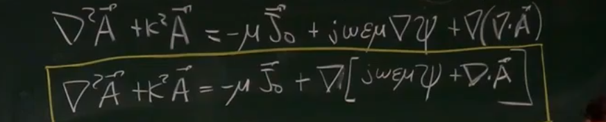
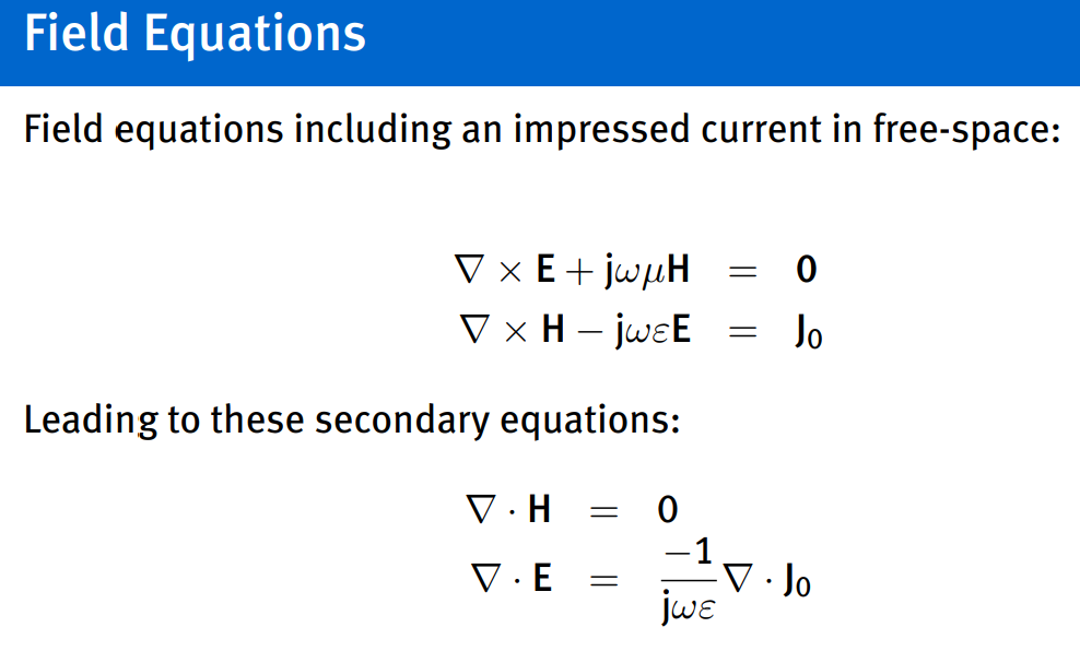
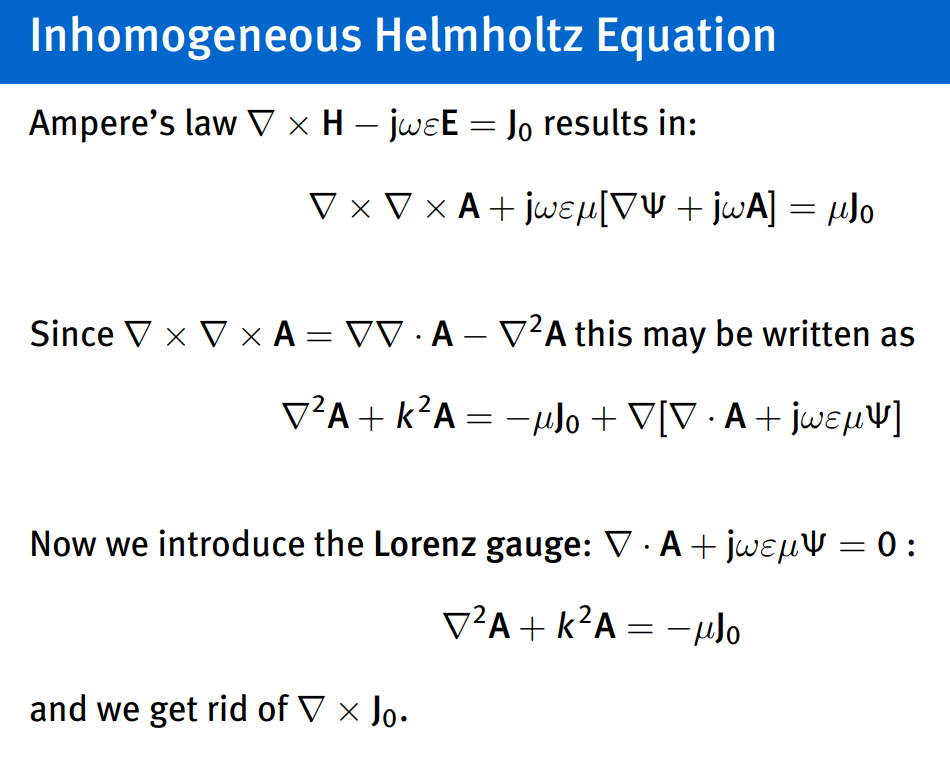
we can eliminate E
Point Dipole
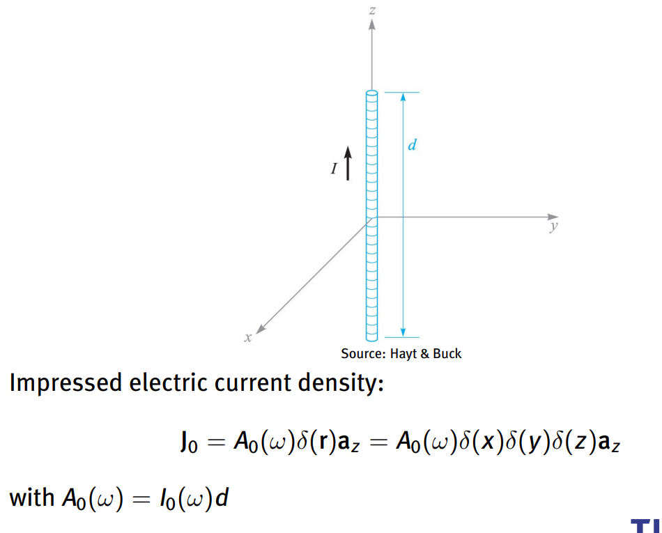
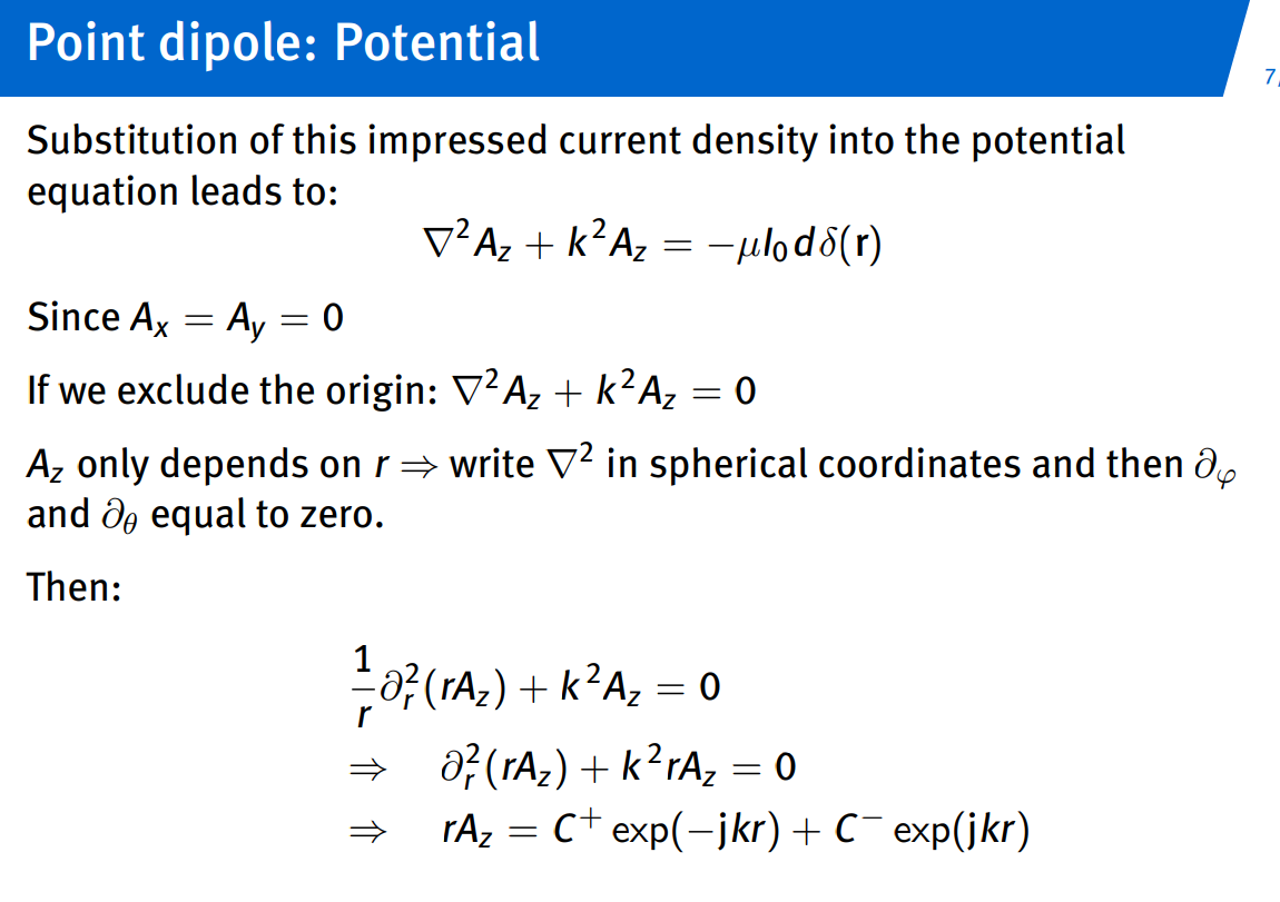
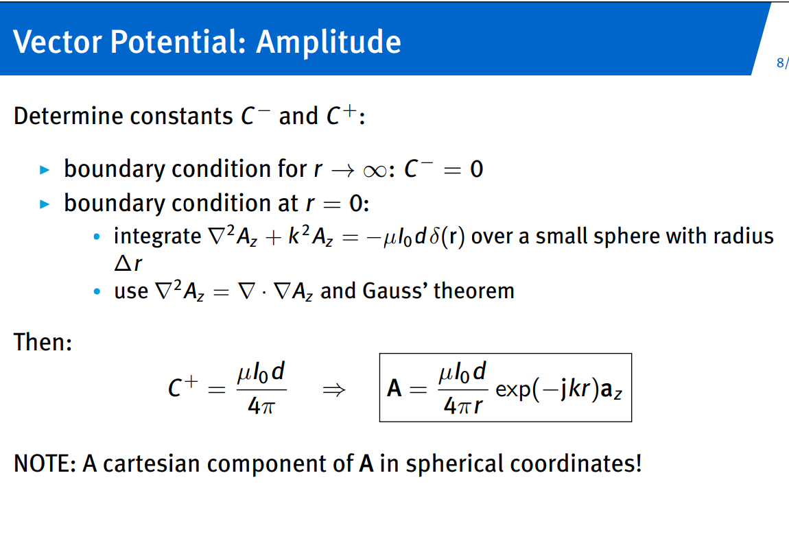
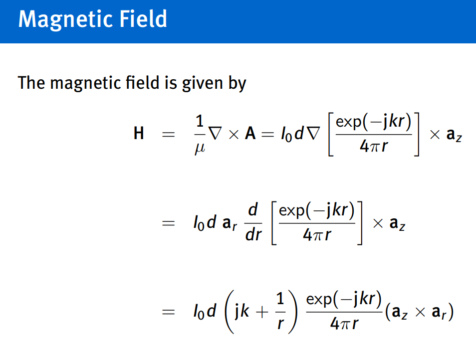
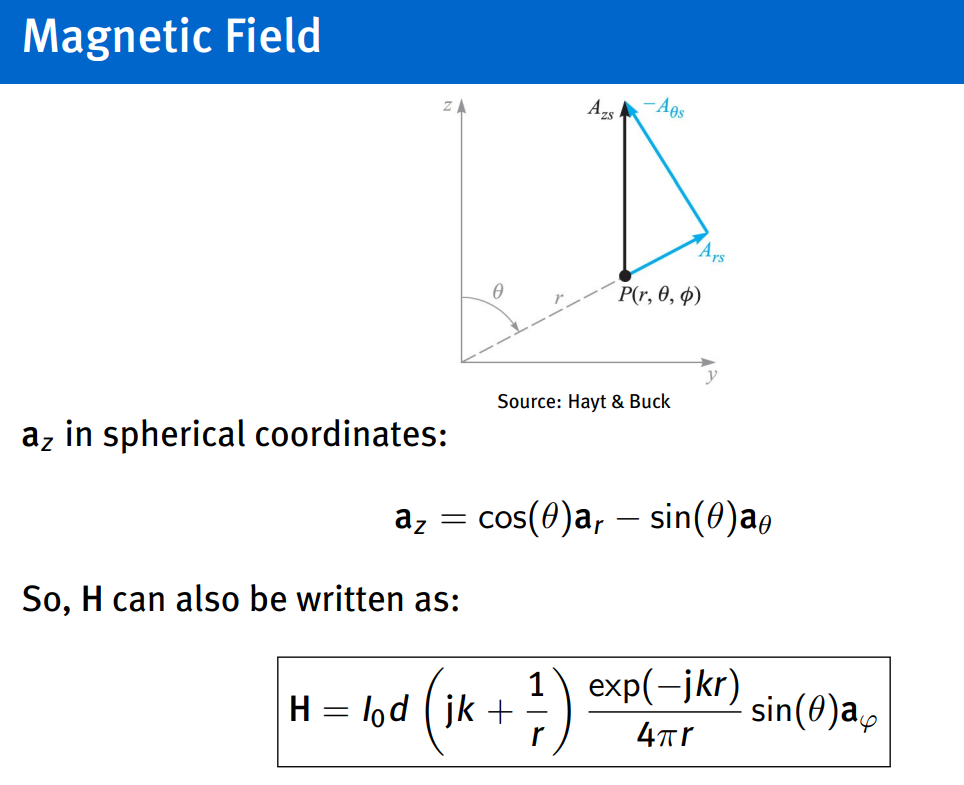
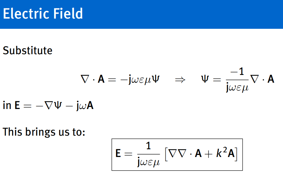
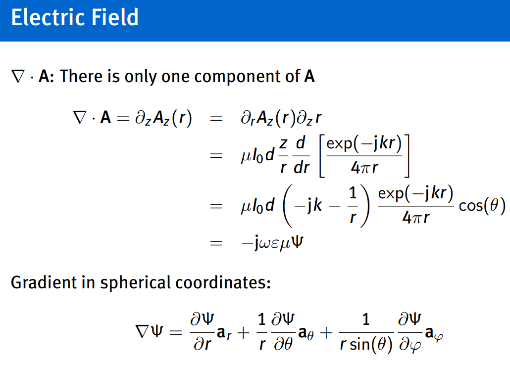
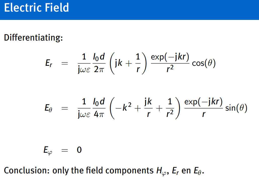
- The solution is a spherical, two-dimensional wave: the fields only depend on r and θ.
- The solution is a TM-wave: there is no magnetic field component in the direction of propagation.
- The wave propagates radially in all directions.
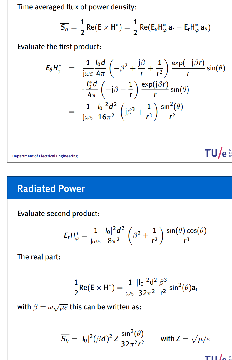
Magnetic point dipole & Antenna Specifications
Topic: Antennas and Radiation
Near and far field - Wikipedia
where antenna radiates: radiation pattern…
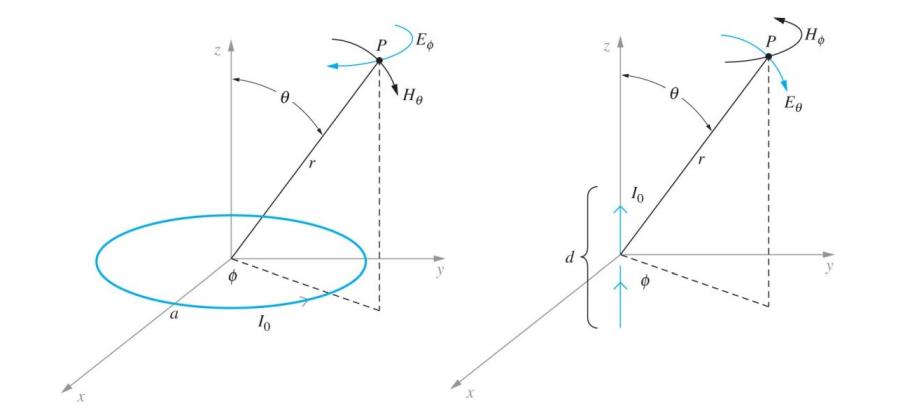
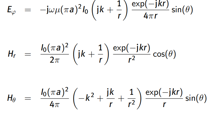
solving magnetic dipole:
- working out fields
- using duality
- using potentials
duality
pick solutions for electric dipole and replace:
potentials
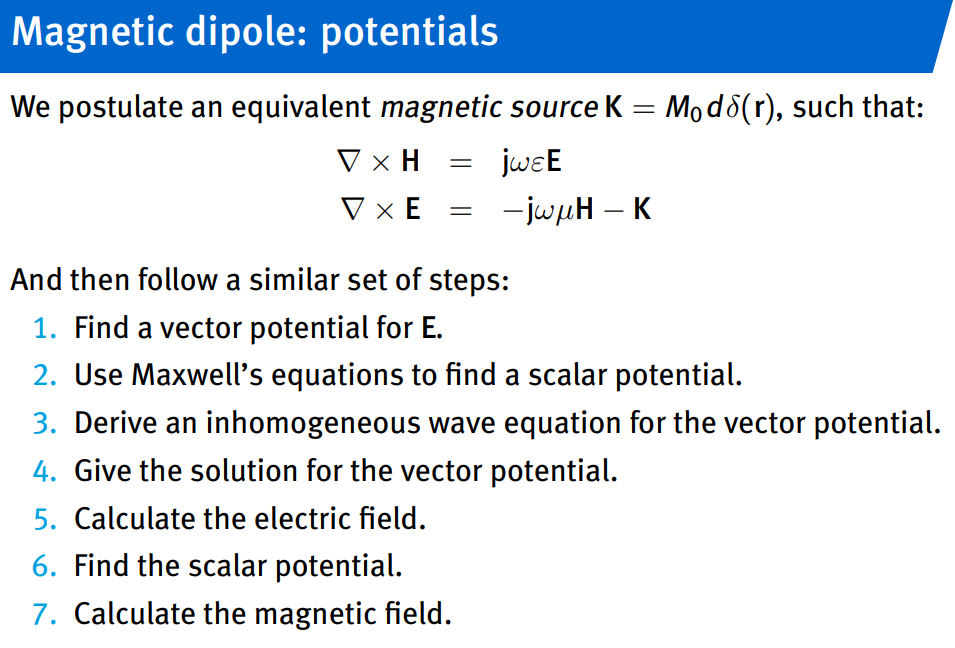
antennas
far field, radiation pattern, radiation resistance, directive gain
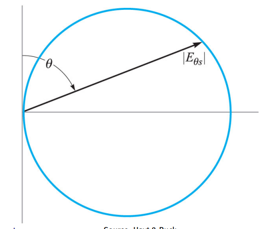
far field
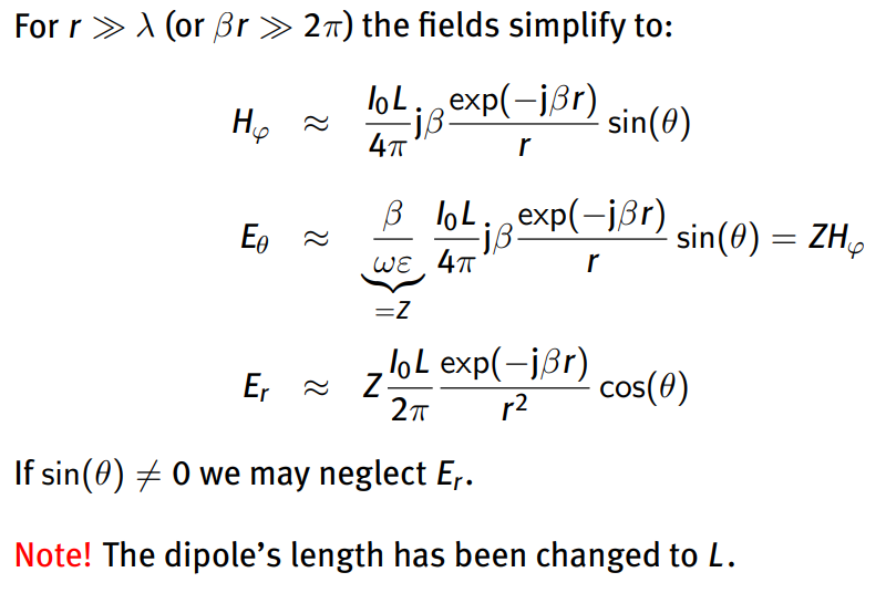
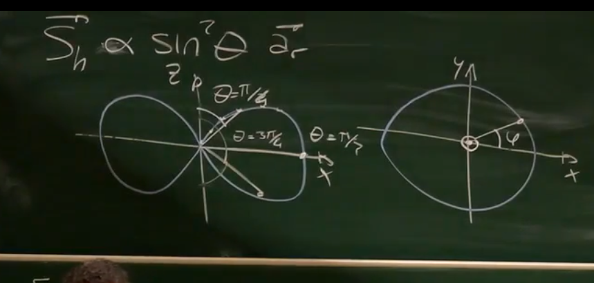
radiation pattern
as shown on the picture of the board its a polar diagram
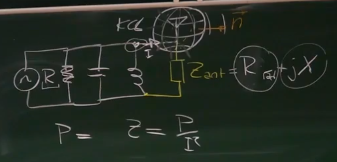
radiation resistance
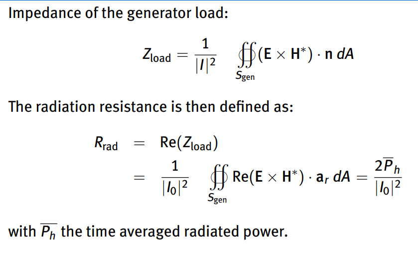
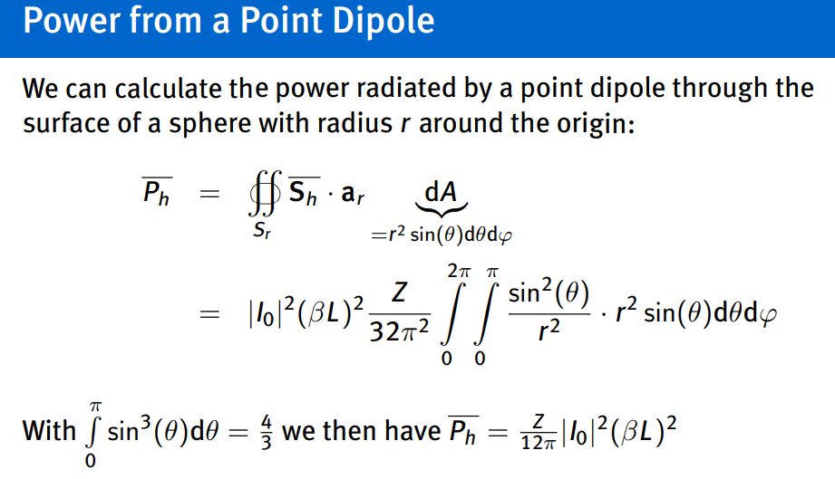
as derived on the board, its needed to have a proper antenna circuit, we only care about the real part…
directive gain
The directive gain of an antenna is the ratio of the maximum power flux in the far field, and total power divided by
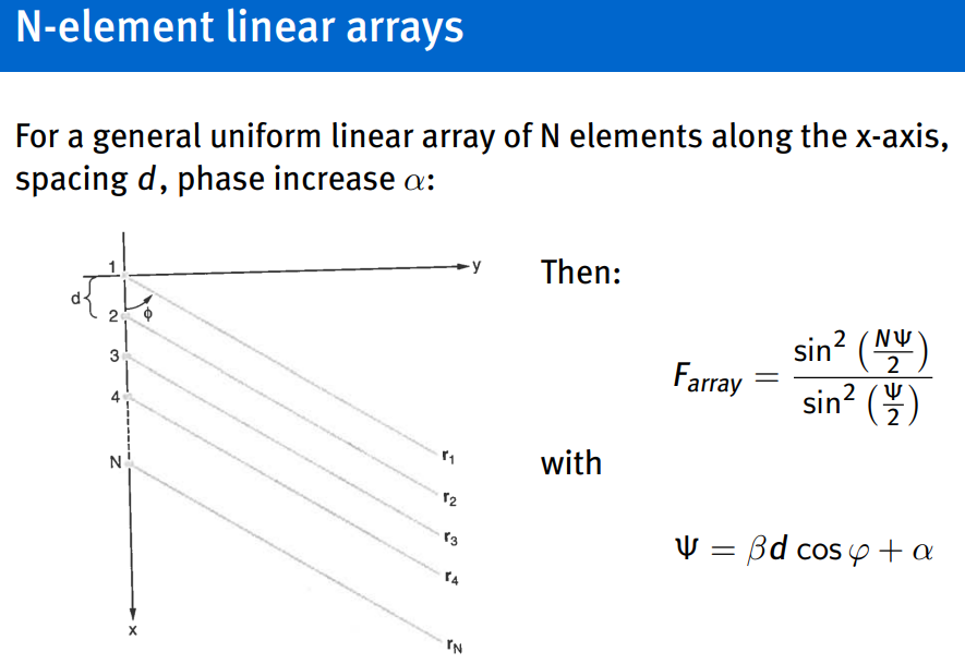
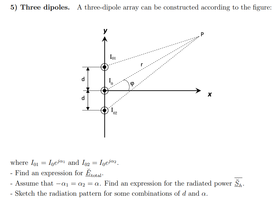
Dipole Arrays
Topic: Antennas and Radiation
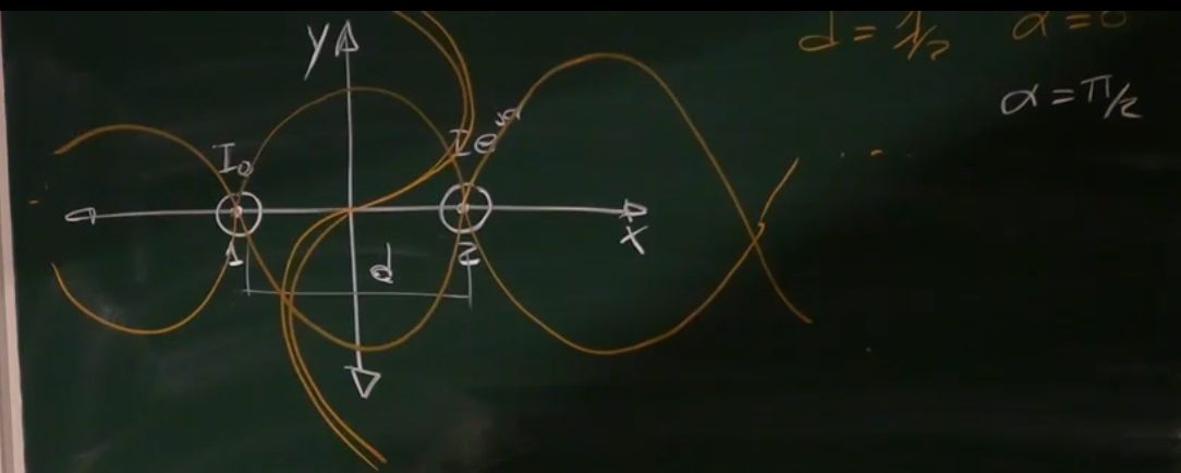
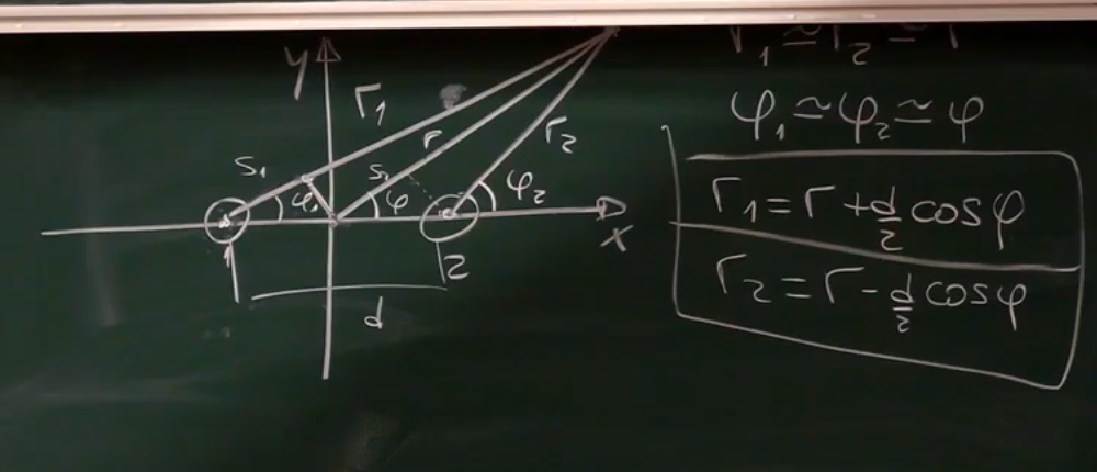
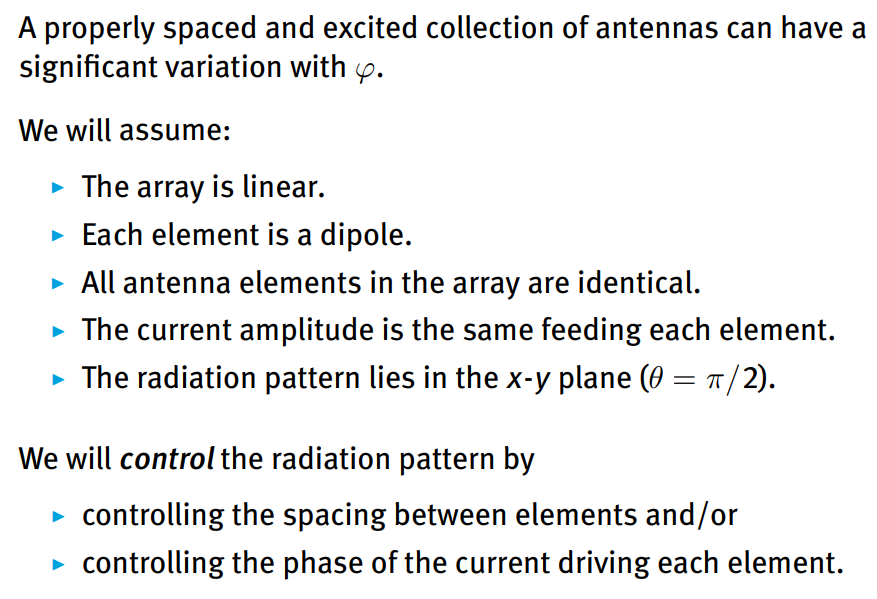
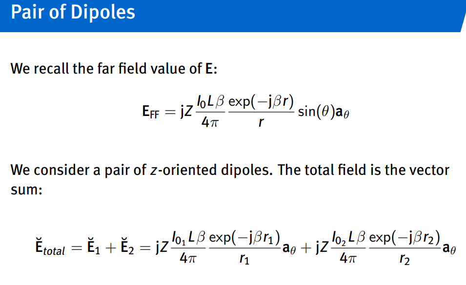
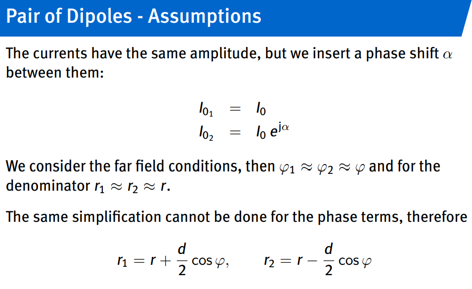
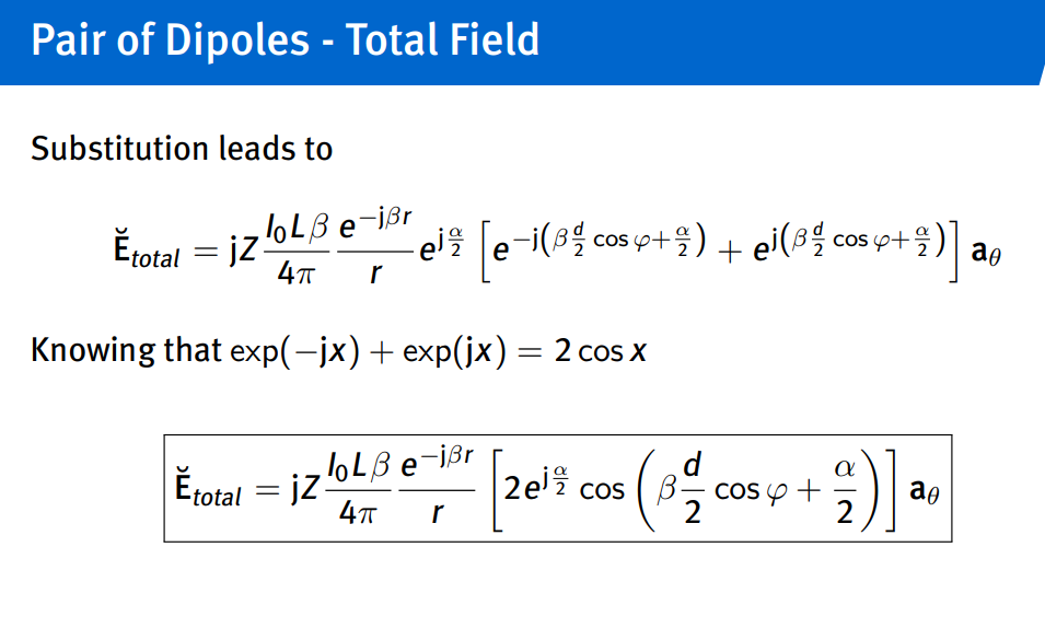
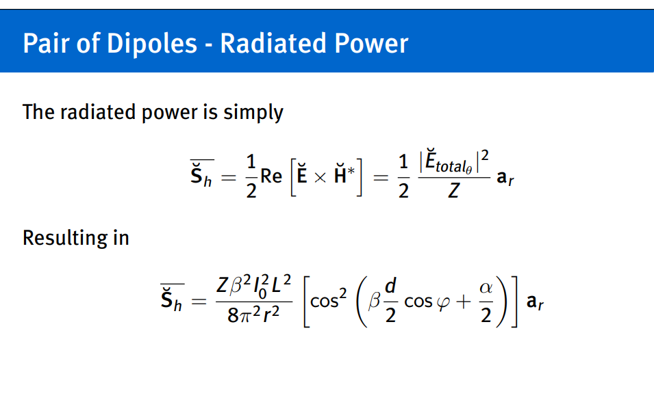
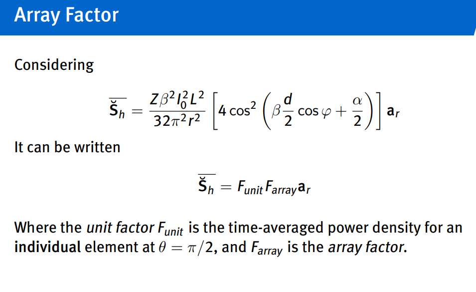
controlling distance and phase…