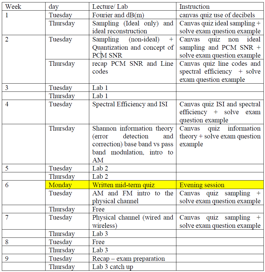
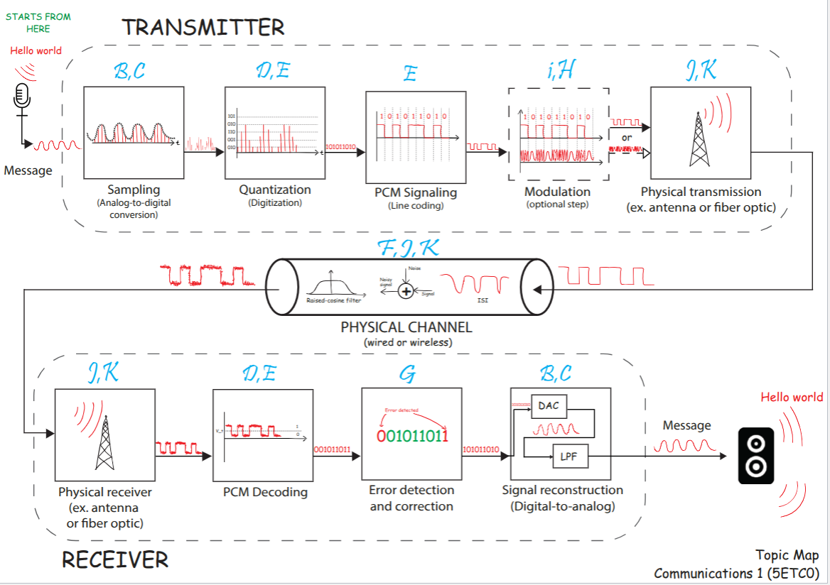
5ETC0 Communication 1
- Area: Communications and Networking
- Topics: Fourier Transform · Sampling · Filters · Random Signals and Power Spectral Density · Data Converters · Noise · Modulation · Digital Signaling and Pulse Shaping · Detection and Matched Filters · Channel Capacity · Wireless Channel · Networks and Error Control
- Related courses: Communication Theory - 5ETB0 · Telecommunications Systems - 5XTA0 · Signals II (DSP Fundamentals) - 5ESC0
POWERS ALWAYS IN DBM
CONVERSIONS BETWEEN W AND DB ALWAYS NOT DBM
ADDITION IN DB = MULTIPLICATION IN W → same for div/sub
snr = dB
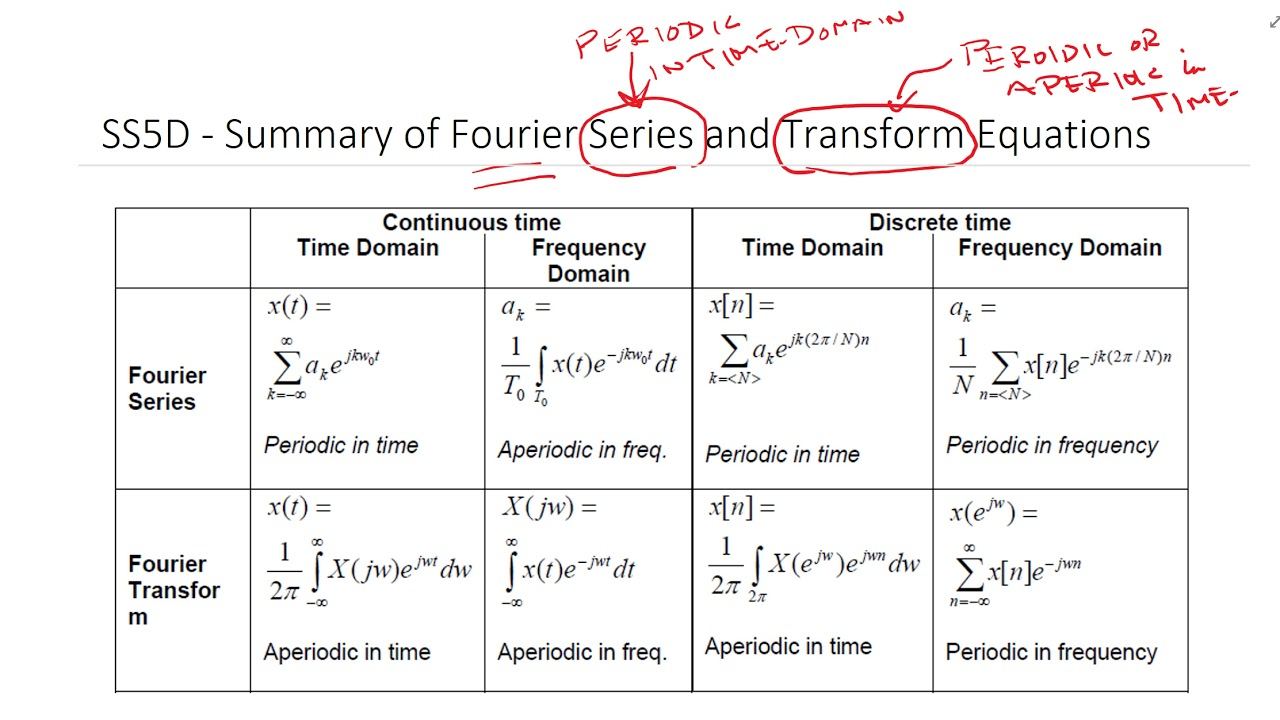
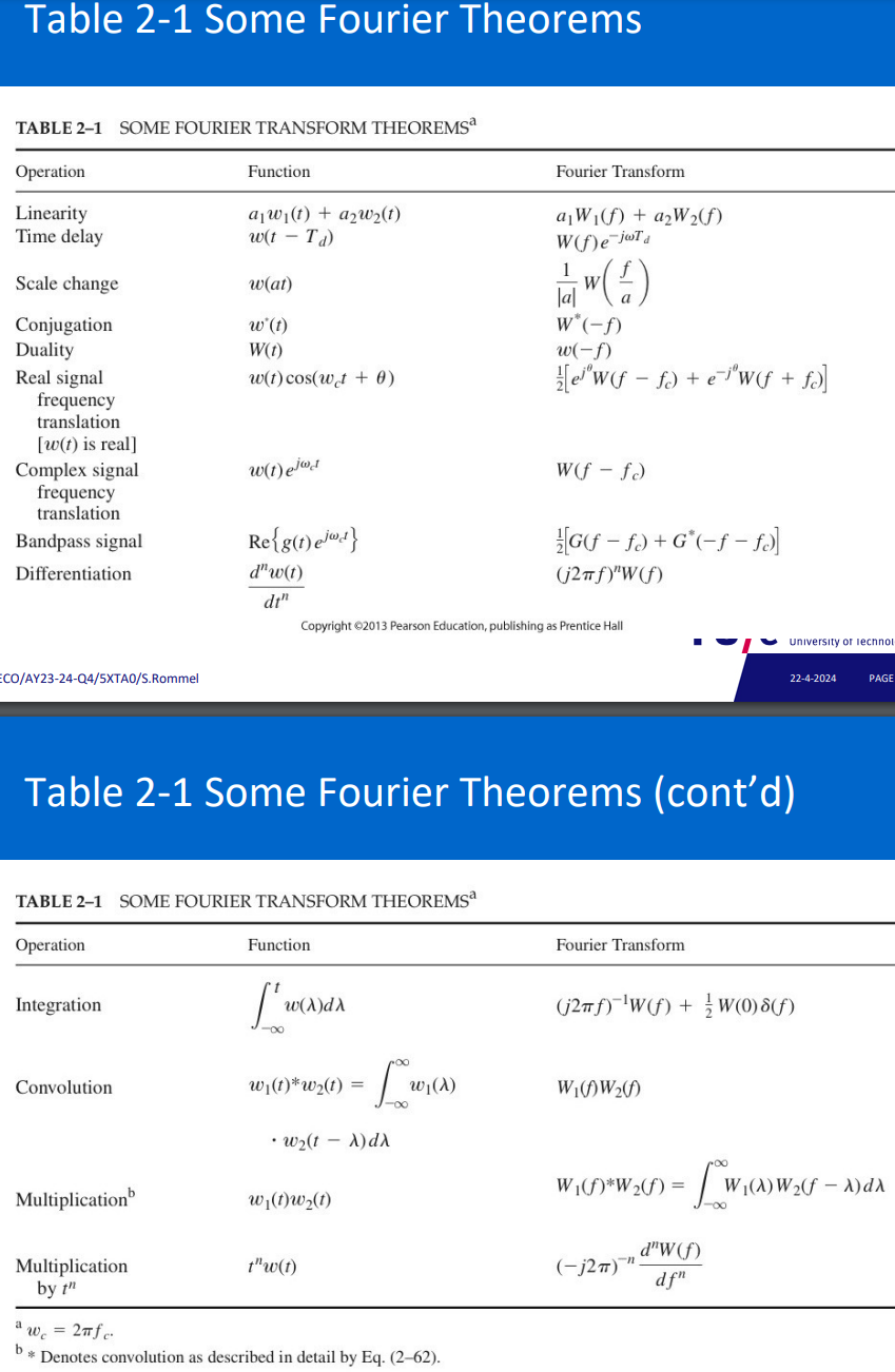
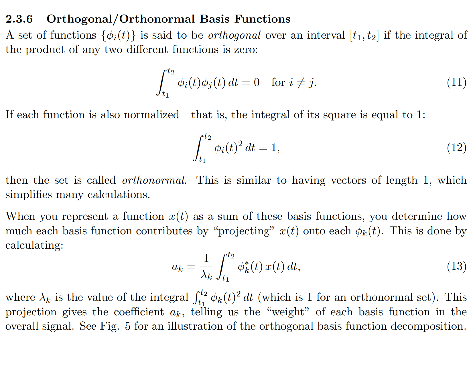
Orthogonal basis and the Fourier transform/series
Topic: Fourier Transform
Fourier series
- Periodic functions approximated by sines and cosines series.
- Conversion affects phase, not RMS/power content.
- Symmetry indicated by only odd/even components.
- Time ←> Frequency domain conversion.
$F(\omega)=\int_{-\infty}^{\infty} f(t)\cdot \cos(\omega t) , dt \text{ or } F(\omega)=\int_{-\infty}^{\infty} f(t)\cdot \sin(\omega t) , dt$$
- Gibbs phenomenon: Overshoot constant with increased bandwidth.
- Fourier coefficients: Represent magnitude and phase of sine/cosine components in a Fourier series.
- Fourier series: Represents periodic waveforms as combinations of sine and cosine waves.
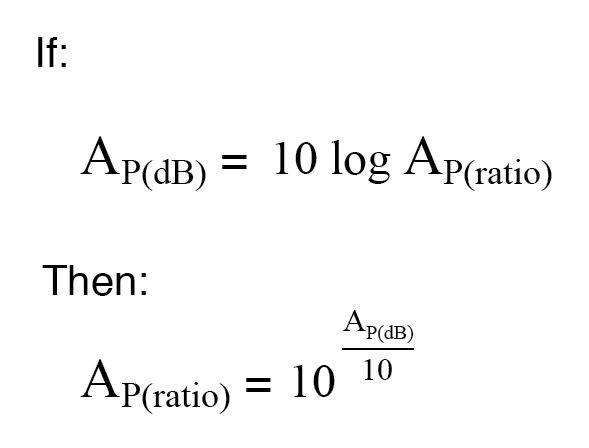
Decibels
power amplification:
power attenuation:
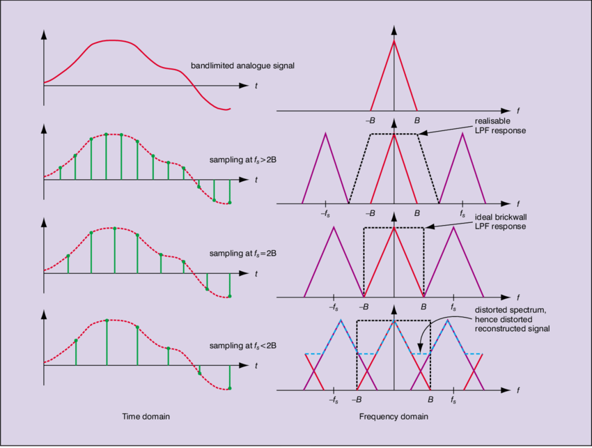
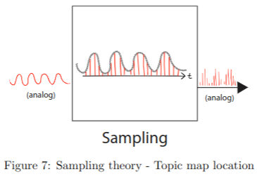
Sampling theory
Topic: Sampling
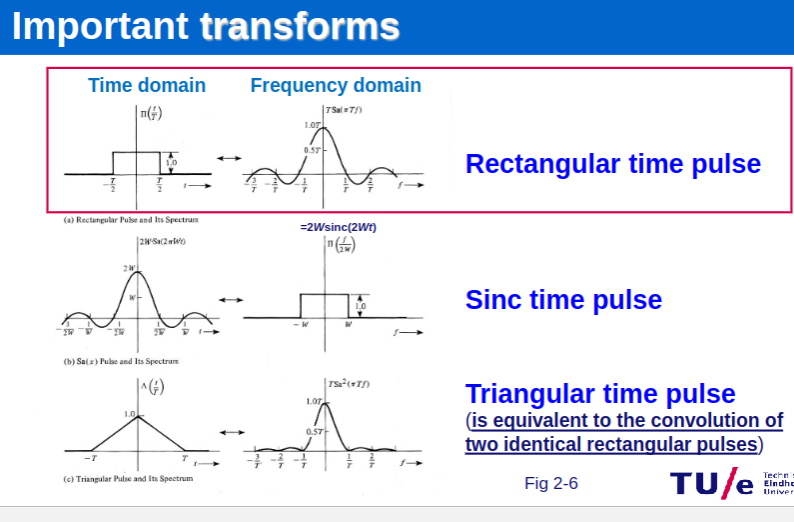
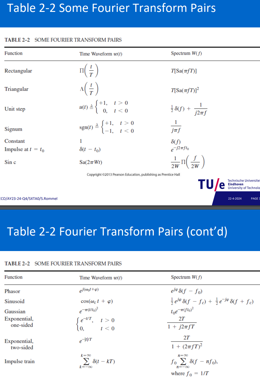
(t) dirac pulse ⇒ (f) Constant amplitude full spectrum (can also be seen as infinitely wide sinc)
(t) long rect pulse ⇒ (f) narrow sinc
(t) short rect pulse ⇒ (f) long sinc : https://www.youtube.com/watch?v=ZcTWLwXGql0&list=WL&index=35
(t) infinitely long transmission ⇒ (f) dirac pulse
max bandwidth frequency means the means: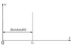
Sampling
https://www.youtube.com/watch?v=iQaFDpiNOlA&list=PLBlnK6fEyqRioD2C9Sa2Kf5Ms35GE8Eq1
band-limited: signal has non-zero frequency components only for a limited part of the frequency spectrum.
time-limited: signal has non-zero amplitude only for a limited part of the time
A waveform is either time-limited or band-limited; not both
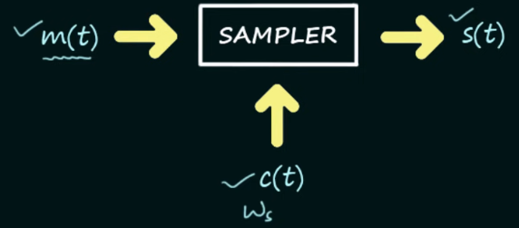
sampling: continous to discrete time signal:
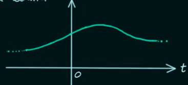 ⇒
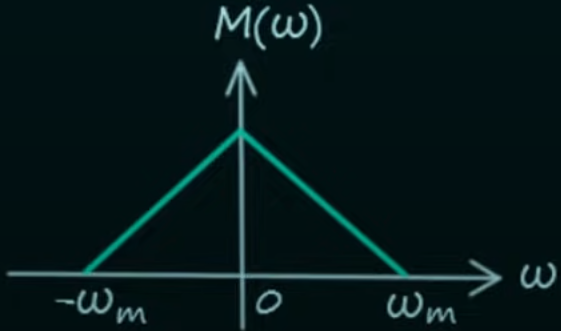
(dirac comb) 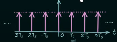
sampler: 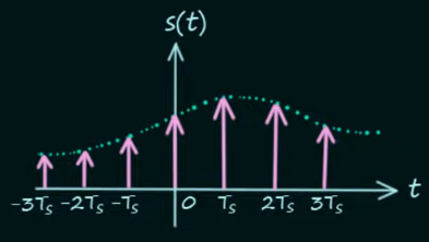 ⇒fourier transform:
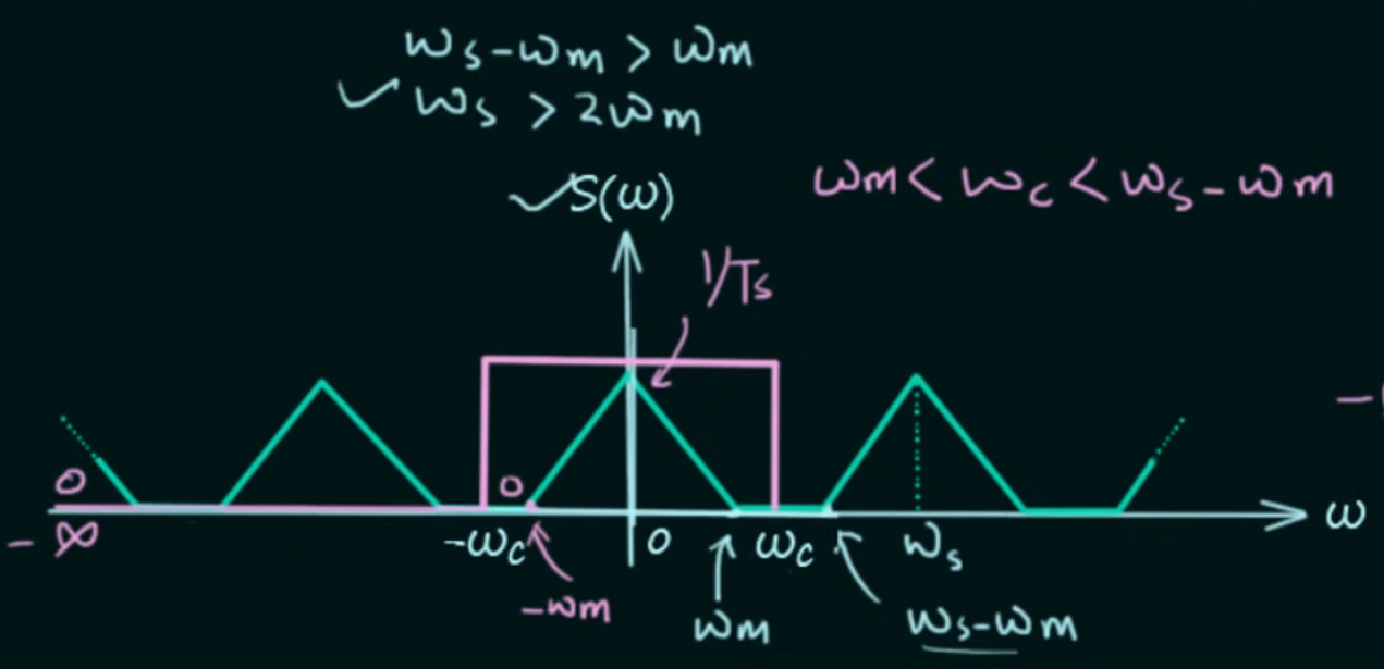
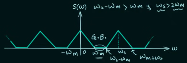 for no overlapping Nyquist’s sampling rate criteria:
now we represent continuous signal
oversampling: Number of independent pieces of info:
dimensionality:
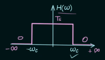
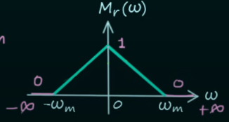
Reconstruction
https://www.youtube.com/watch?v=rmDg3eVWT8E
 ⇒
 ⇒inverse fourier transform:
Sampling Methods (Pulse Amplitude Modulation)
Topic: Sampling
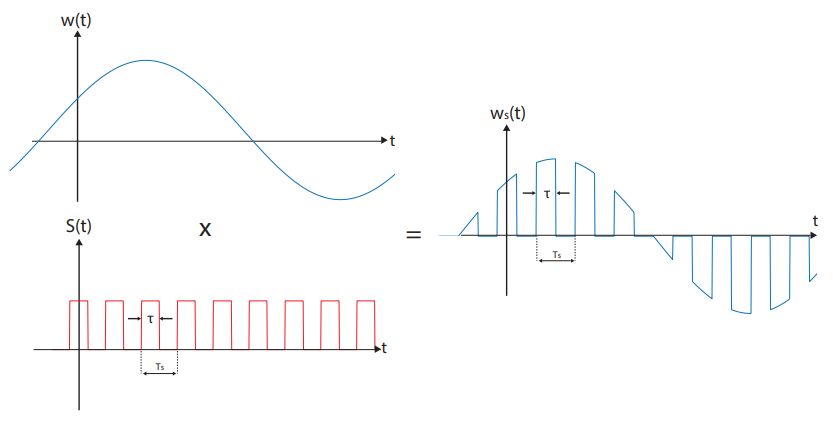
Signals Sampling Techniques
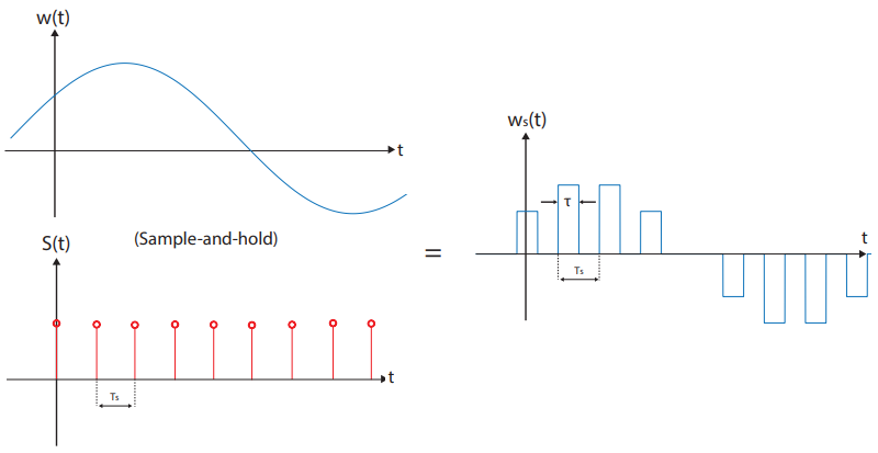
Gating (natural sampling)
- Natural Sampling Summary:
- Analog signal
passes for certain time only - Sampling:
; . - Clock: Duty cycle
. - Signal Representation:
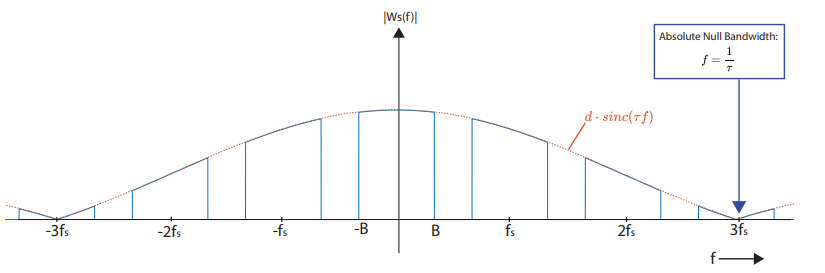
; . - Fourier Series:
. - Absolute Null Bandwidth: First zero at
. (first position at which spectrum not repeated).
- Sampling:
The Fourier transform of a PN code produces a line spectrum for which the magnitude is confined by a sinc function. The first null of the sinc function occurs at frequency equivalent to the bit rate of the PN code. For example, a bit rate of 10 MBits/s translates to a frequency at the first null of 10 Mhz. Since the magnitude of the spectrum is symmetrical around DC, the null-to-null bandwidth is twice the bit rate - 20 MHz.
Definitions - ITS
- Key Metrics: Bandwidth
; Sampling frequency ; Duty cycle .
- can reconstruct the original signal since we obtain frequency copies of the original analog waveform that are undistorted just may differ in magnitude scaling
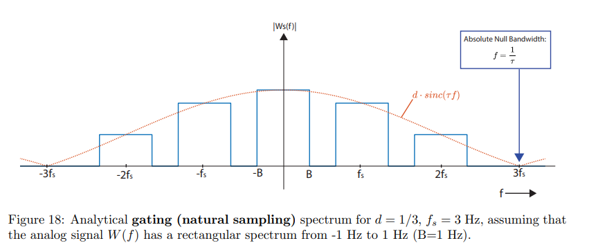
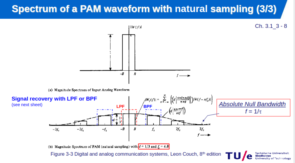
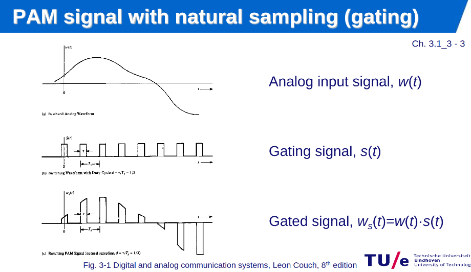

with natural sampling the shape of the spectra remain identical to the original spectrum, as natural sampling preserves continuous amplitude inside each pulse so after ideal low pass filtering the baseband spectrum shape is unchanged while for flat-top it introduces amplitude variation (sinc distorion).
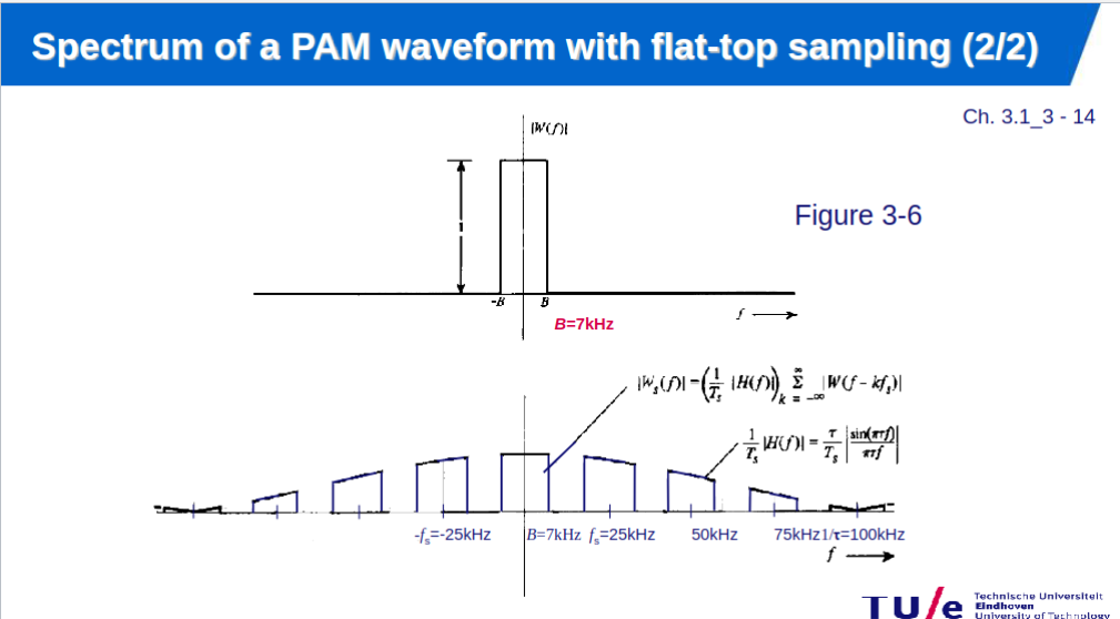
Flat-top sampling (instantaneous sampling)
The resulting spectra is the product of the ideal sampling spectrum and the sinc function.
if
- Flat-top Sampling:
- Instant captures at
; constant hold for . - Yields stable digital conversion levels.
- Can reconstruct using nyquist filtering. Not fully due to distortion.
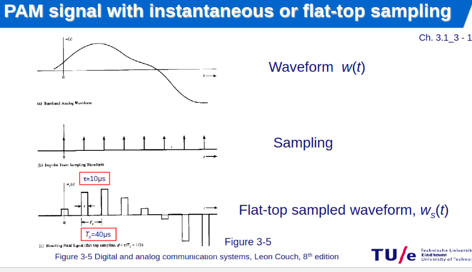
- Instant captures at
- Formulation:
, is square pulse. - Fourier:
, .
- Aperture Effect Mitigation (high-frequency components might be altered):
- Narrow
. - Equalization:
filter.
- Narrow

Digitization
Topic: Data Converters
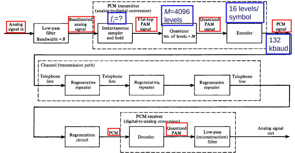
Pulse Code Modulation (PCM)
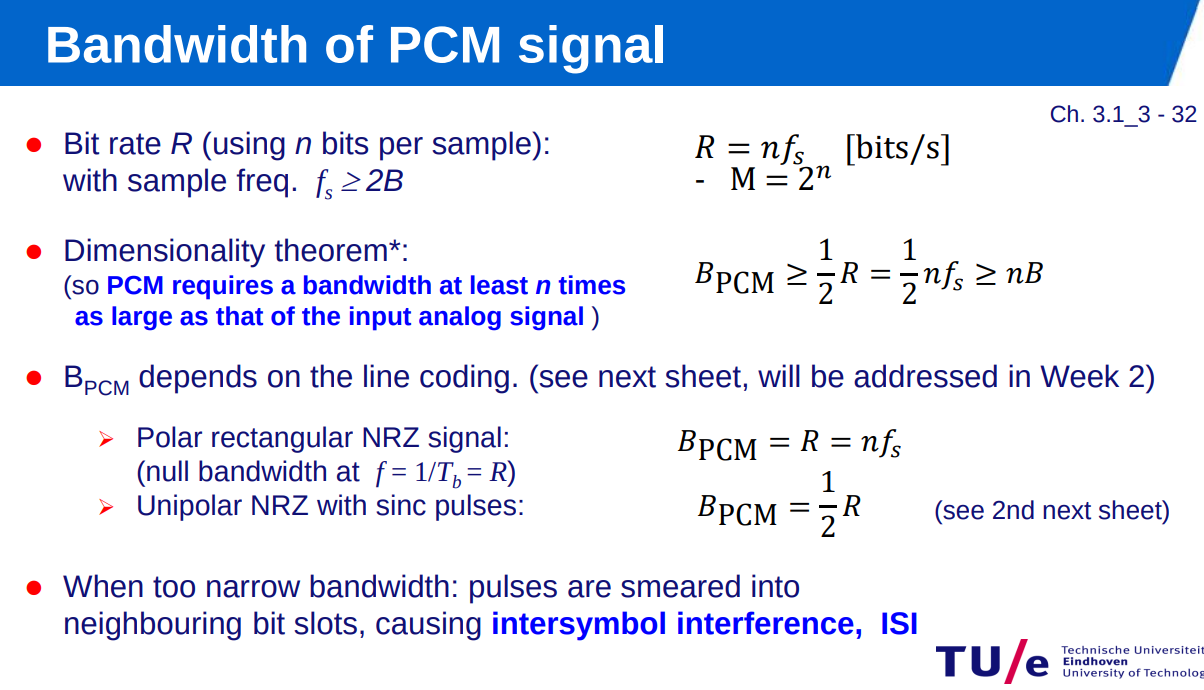
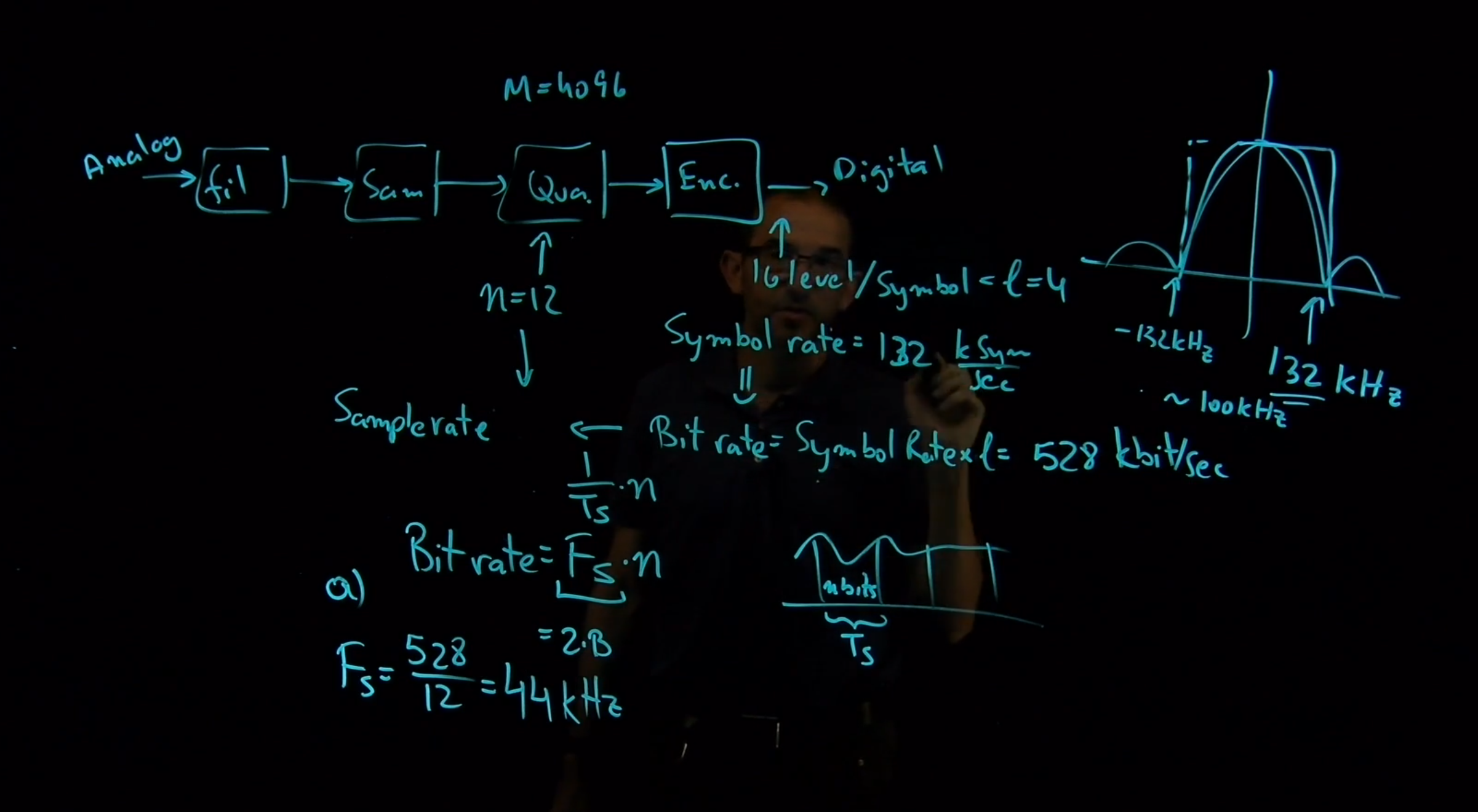
Bandwidth of PCM signal depends on the bit rate and the pulse shape.
Let the bit rate be R (of the PCM signal generated), then
R = n*fs
n = number of bits on the PCM word (M= 2^n …. M is no. of levels of quantization)
fs = sampling rate to which analog signal is sampled
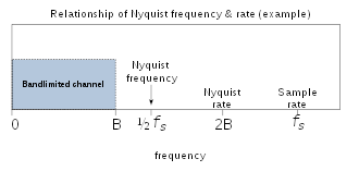
For no aliasing i.e. the Nyquist rate : fs= 2B,
where B is the bandwidth of the analog signal that is to be converted.
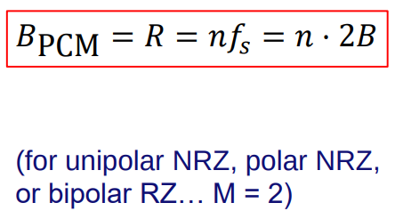
Bandwidth of the PCM (BPCM) waveform is bounded by
BPCM>= R/2
BPCM>= n*B
(so R/2 is the minimum bandwidth of the PCM signal)
For one using a rectangular pulse with polar NRZ (Non return to zero) line code:
BPCM = R = nfs = n2*B
This means the bandwidth of PCM is greater than the bandwidth of the analog signal.
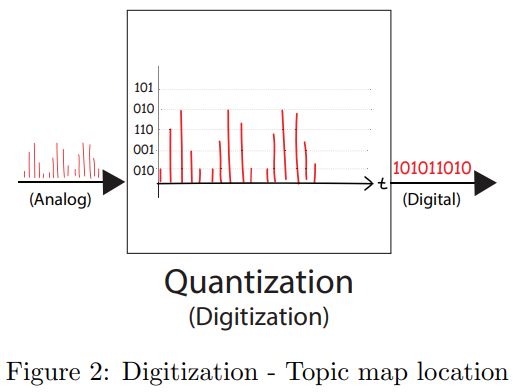
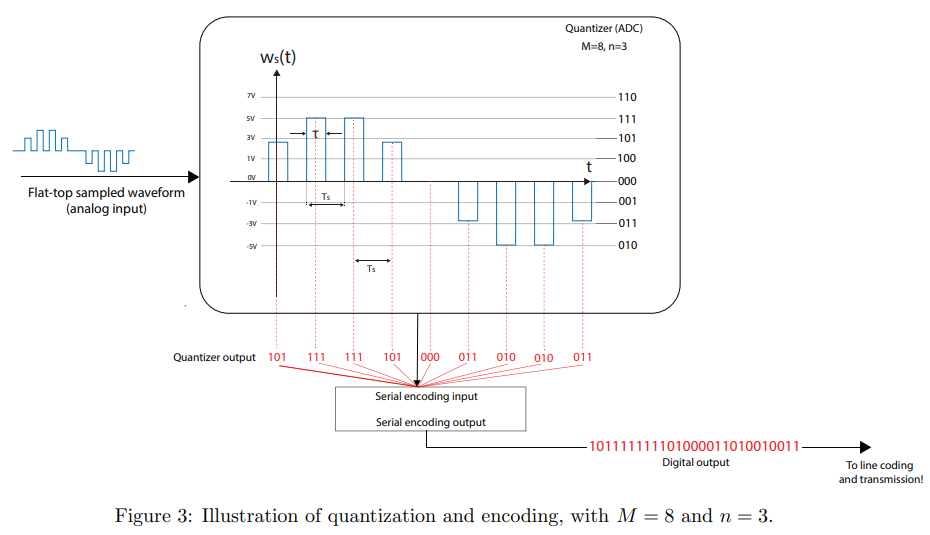
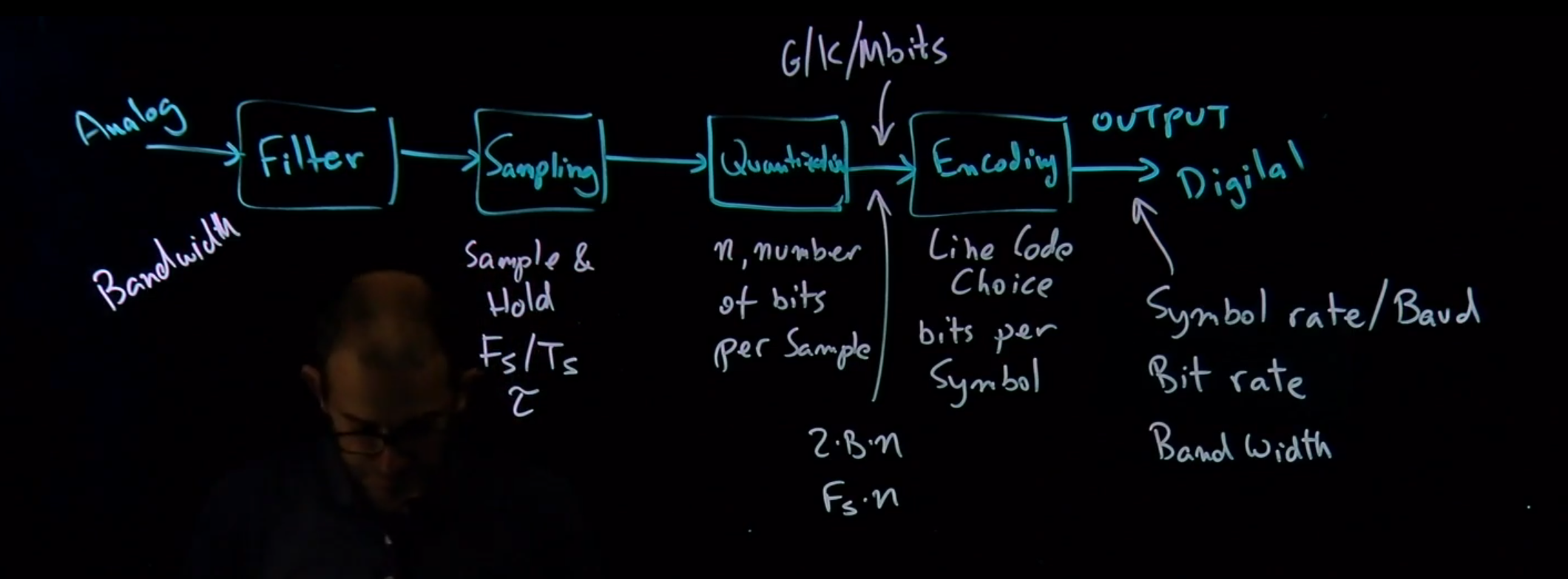
PCM involves converting an analog signal into a digital one through santizmpling, quaation, and binary encoding. The process starts by sampling the analog signal at or above the Nyquist rate, then quantizing these samples into discrete levels, and finally encoding these levels into binary digits.
-
digital: better snr
-
time to send independent of amount/time of duration of info sent
-
but more bandwidth needed.
-
Quantization Levels: Determined by
, where is the number of bits per sample. -
Bit-rate (
): Defined as (bits/s), where is the sampling frequency, satisfying nyquist criteria with being the analog signal bandwidth. -
Spectral Efficiency (
): Given by (bits/s)/Hz, indicating how efficiently the bandwidth is used. can be bigger than 2 in that case multilevel. -
Minimum Bandwidth (
): The least bandwidth required, , necessary to avoid intersymbol interference (ISI) and ensure signal integrity.
Signal-to-noise ratio
Topic: Noise
Signal-to-noise ratio - Wikipedia
Noise spectral density - Wikipediai
not mentioned in the reader:
-
same but addition in in dBm and dB -
-
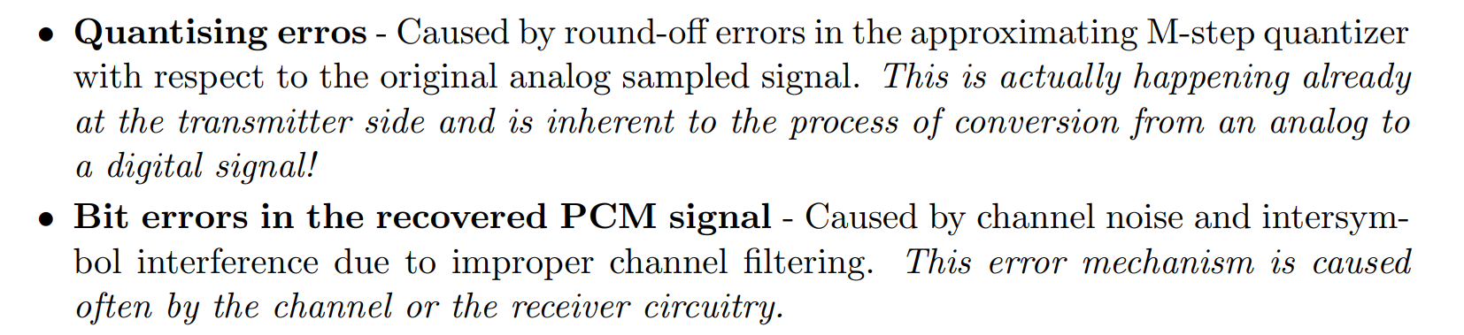
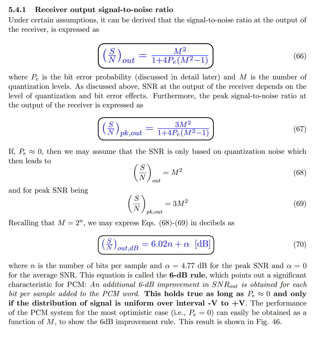
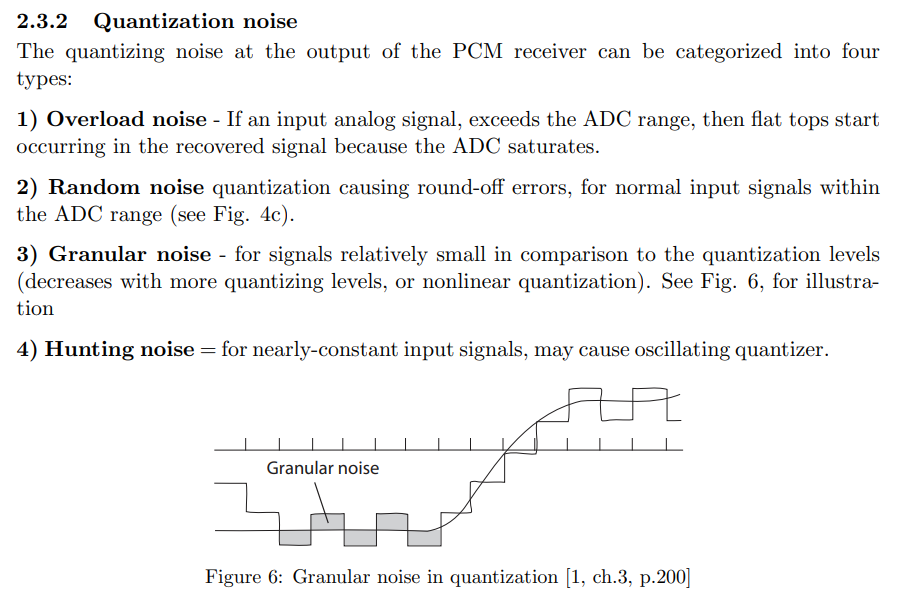
Quantization Noise: Caused by rounding errors in M-step quantizer.
-
Bit errors in the recovered PCM signal: caused by channel noise and intersymbol interference due to improper channel filtering.
-
Aliasing noise: due to non-ideal band limitation (usually most time signals even audio ones are not fully band-limited to 40 kHz.)
-
**compander if amplitude not uniform betters pcm performance but cant maximize snr_out but less effect of P_e. (With companding, output SNR relatively insensitive to input level)
-
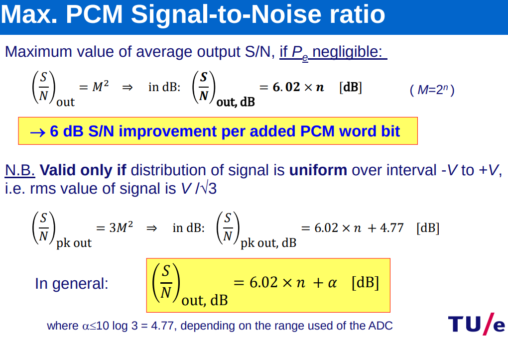
Receiver Output SNR (UNIFORM):
, where is bit error probability. This equation defines the average SNR at the output of the receiver. **The M term is squared because power is proportional to voltage squared. -
Peak SNR:
. -
-
for the peak
and α = 0 for the average SNR. This equation is called the 6-dB rule ⇒
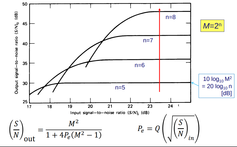
Bit-error Probability
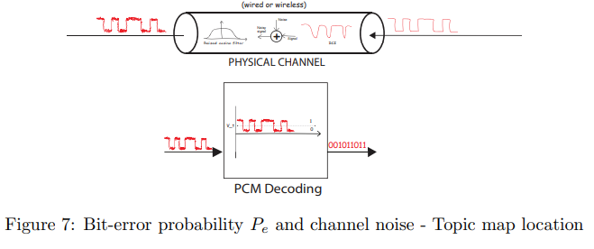
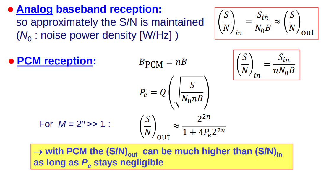
Channel noise, including thermal noise and electromagnetic interference, affects the transmission quality by increasing the bit-error probability (
- AWGN Channels: Characterized by additive, white, and Gaussian noise, impacting the calculation of
through the Q-function, which relates to the tail probability of a Gaussian distribution. - Bit-error Probability:
, showing the dependence on the input SNR. A higher SNR leads to a lower , enhancing transmission reliability.
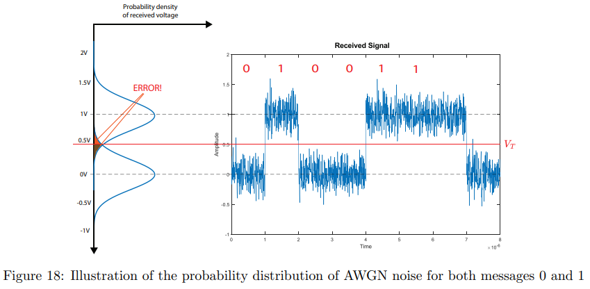
Increasing the number of bits per sample improvesbut can lead to higher channel noise power ( ) due to wider bandwidth, affecting . The interplay between increasing resolution and the bandwidth’s impact on noise illustrates the complex balance in optimizing digital signal transmission.
is noise spectral density used in transmission channel: (use N0/2 because we, by convention, also distribute the noise power over the negative frequencies).
**Ifgiven then
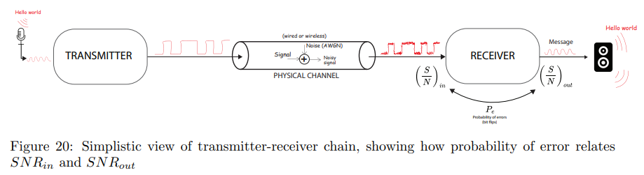
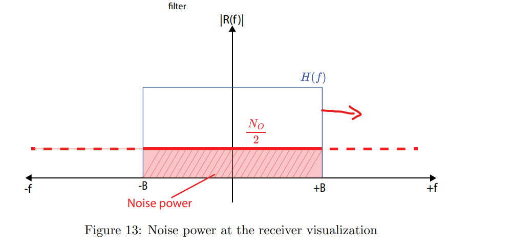
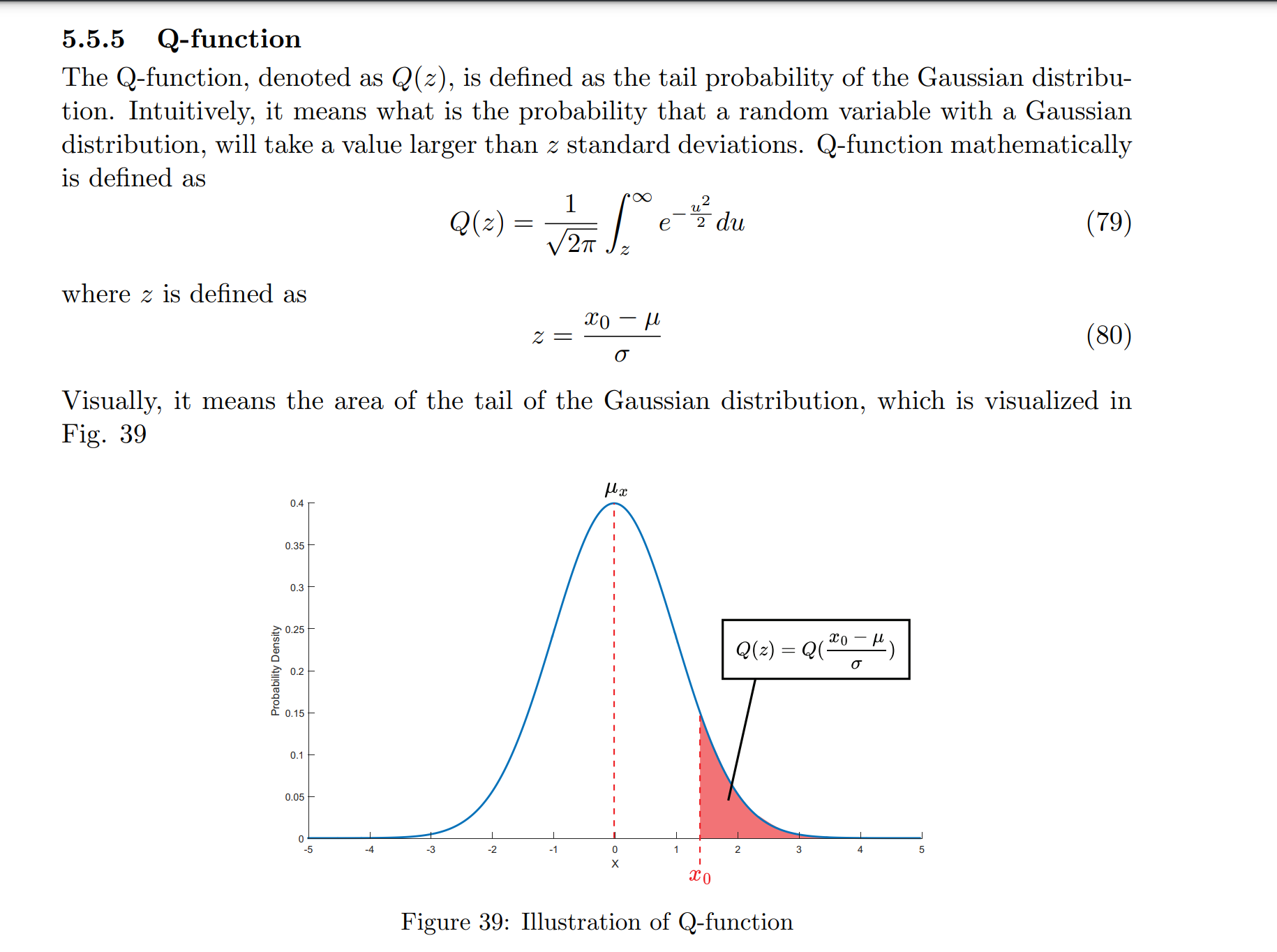
Increasing Number of Bits
Higher Bandwidth Lower Lower Higher Lower - MORE M Levels → HIGHER CHANCE OF OVERLAP OVER THOSE LEVELS →
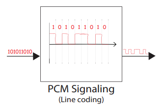
Digital signaling
Topic: Digital Signaling and Pulse Shaping
Line code - Wikipedia
Vectorial representation of digital signaling
Topic: Detection and Matched Filters
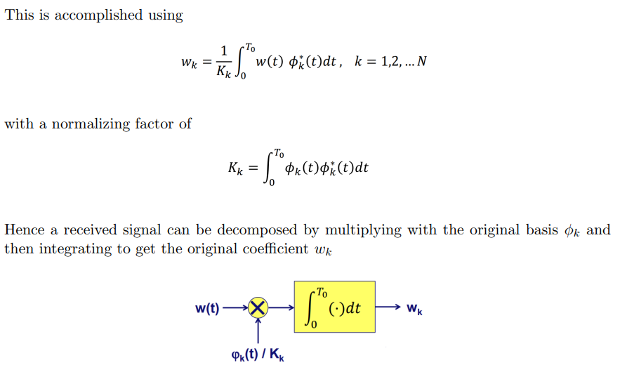
- Orthogonality Condition:
for . - Signal Representation:
. - Signal Reconstruction:
. - Orthogonal Decomposition: Decode signal by integrating with basis function
.
- 3-bit Signal Example:
, with orthogonal basis . dimensions: symbols
Multi-level signaling
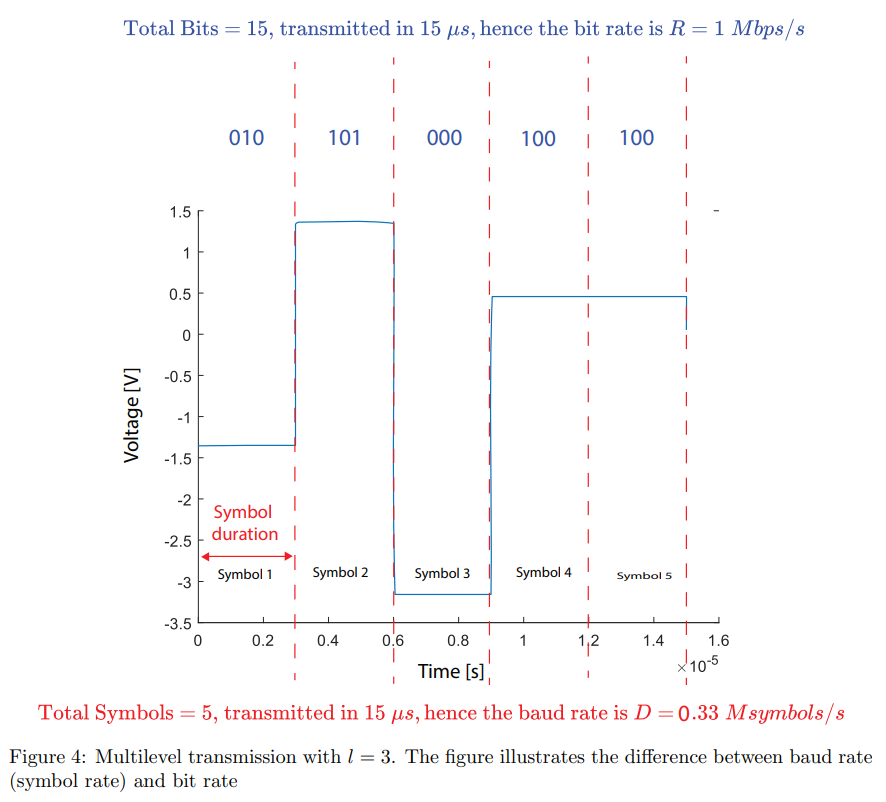
Multi-level signaling sends more than one bit per symbol, enabling higher data rates without increasing bandwidth.
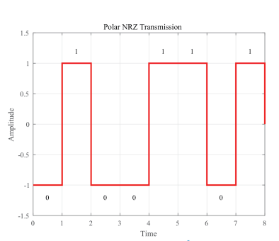
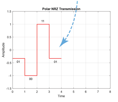
- Levels and Bits Relationship:
(bits per symbol) - Where
is the number of levels per symbol, and is the number of bits per level.
- Pros and Cons: Increases bandwidth efficiency and data rates but introduces greater susceptibility to noise.
- Single-bit vs Multi-level: Multi-level signaling is more bandwidth-efficient but less noise-resistant compared to binary transmission.
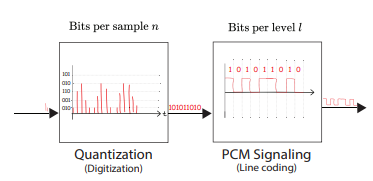
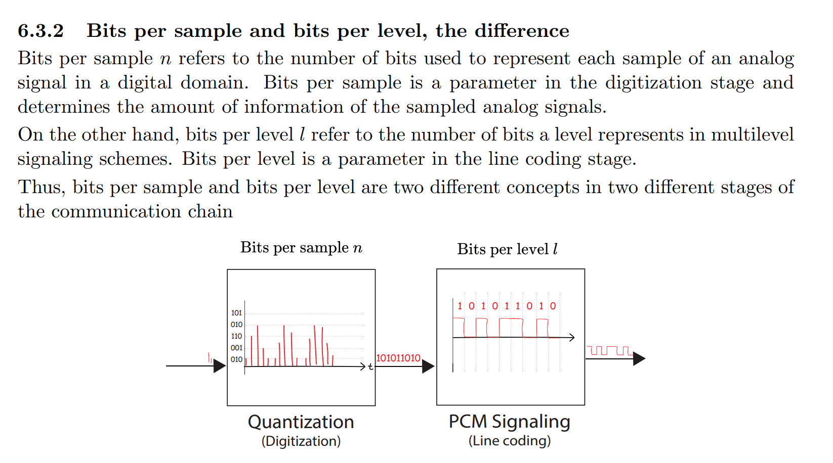
- Bits per Sample vs. Bits per Level:
- Bits per sample (
) refer to digitization (quantization) stage, indicating the resolution of analog to digital conversion. - Bits per level (
) refer to the line coding stage, indicating how many bits are represented by each level in a multi-level signaling scheme.
- Bits per sample (
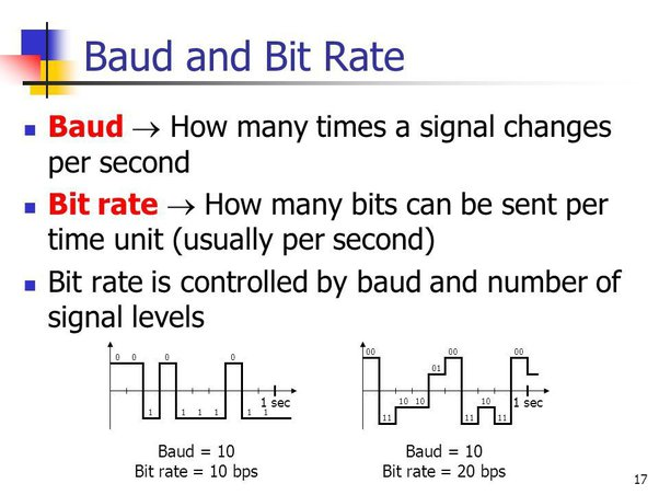
Baud-rate (or Symbol rate)
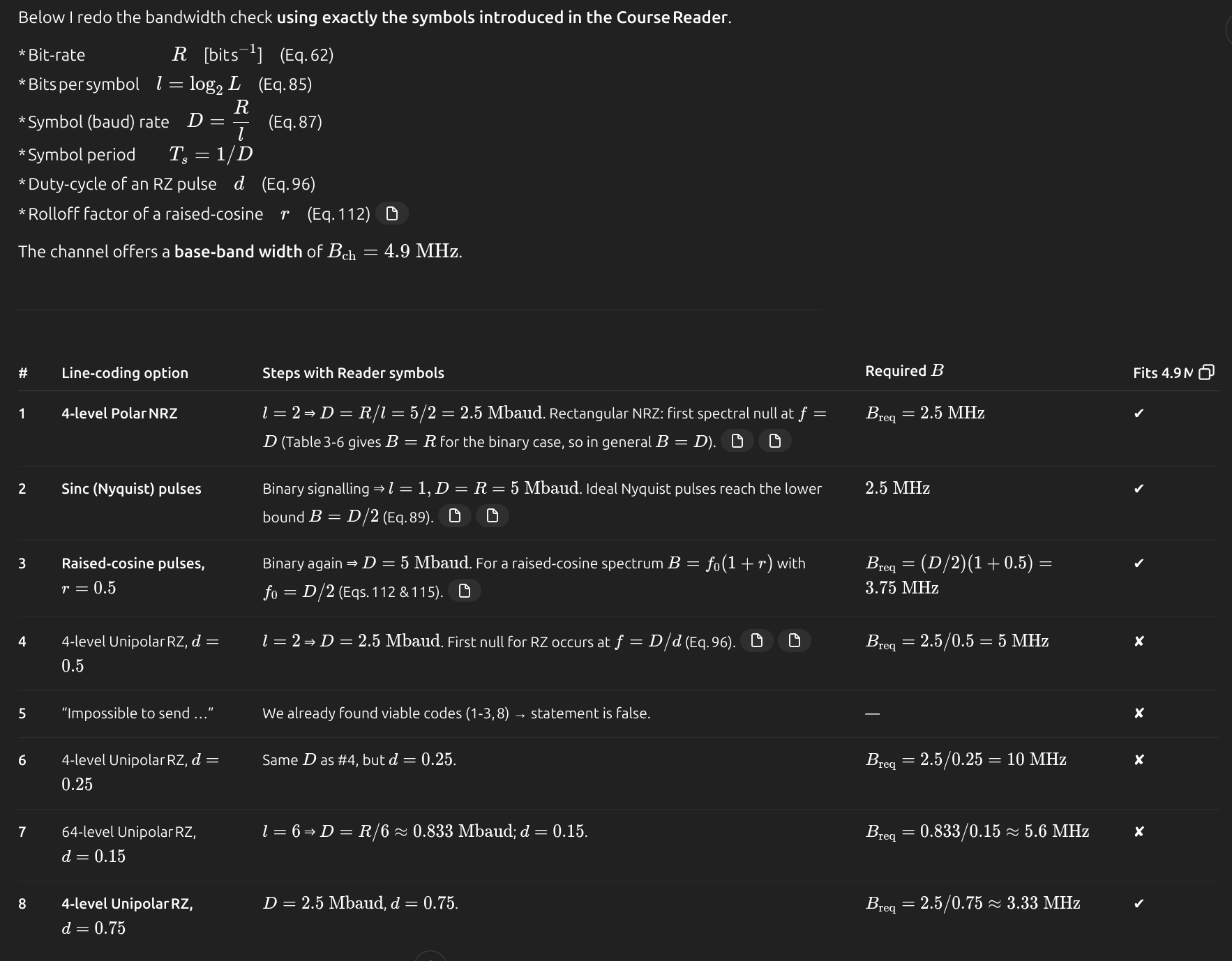
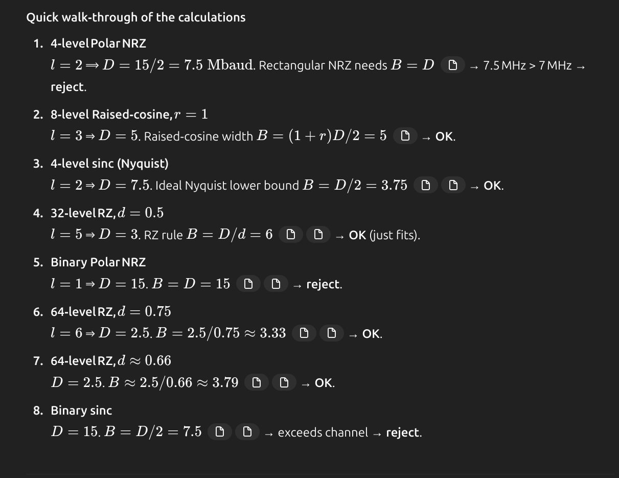
- Baud Rate (
): , where is dimensions, is time per dimension. Number of symbols transmitted per second. also
- Each symbol can represent or/ convey one or several bits of data.
- Bit Rate (
): [bits/s], with levels, baud rate. One symbol can represent multiple bits. - Binary Signaling: For
, . - Channel Capacity:
- Channel Capacity (bps):
- Bandwidth (
): . Minimum bandwidth achieved with sinc pulses. - Dimensionality theorem states the number of orthogonal dimensions
, with as bandwidth and as time period.` - Relationship between bandwidth
and baud rate : . - Baseline wander: occurs when the signal has a strong Low Frequency component, together with AC coupling in the system.
Linecodes and their spectras
Topics: Random Signals and Power Spectral Density · Digital Signaling and Pulse Shaping
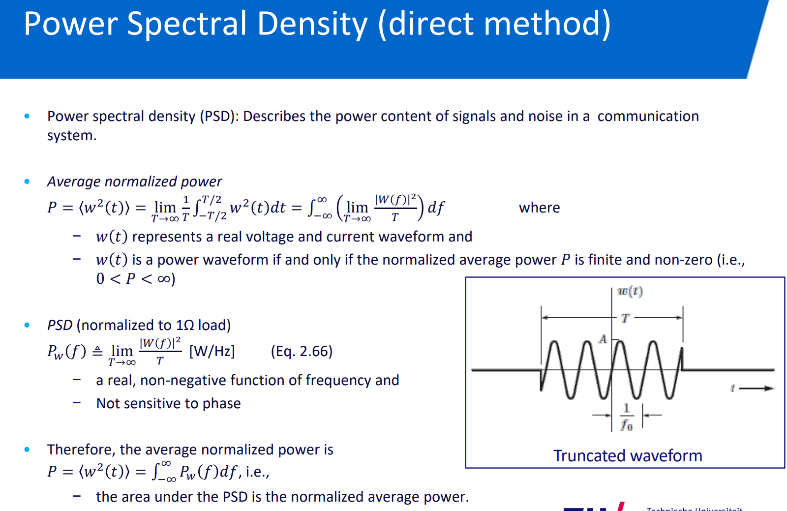
Power spectral density (PSD)
Topic: Random Signals and Power Spectral Density
https://www.youtube.com/watch?v=DoSLMEEo1Y0
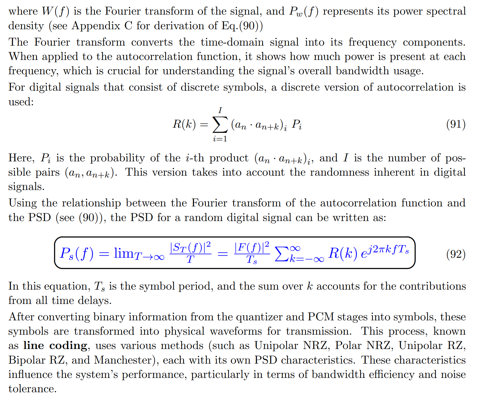
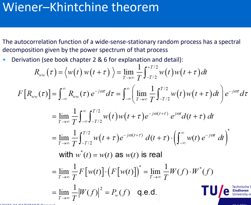
- PSD analyzes signal power across frequencies, akin to an audio EQ.
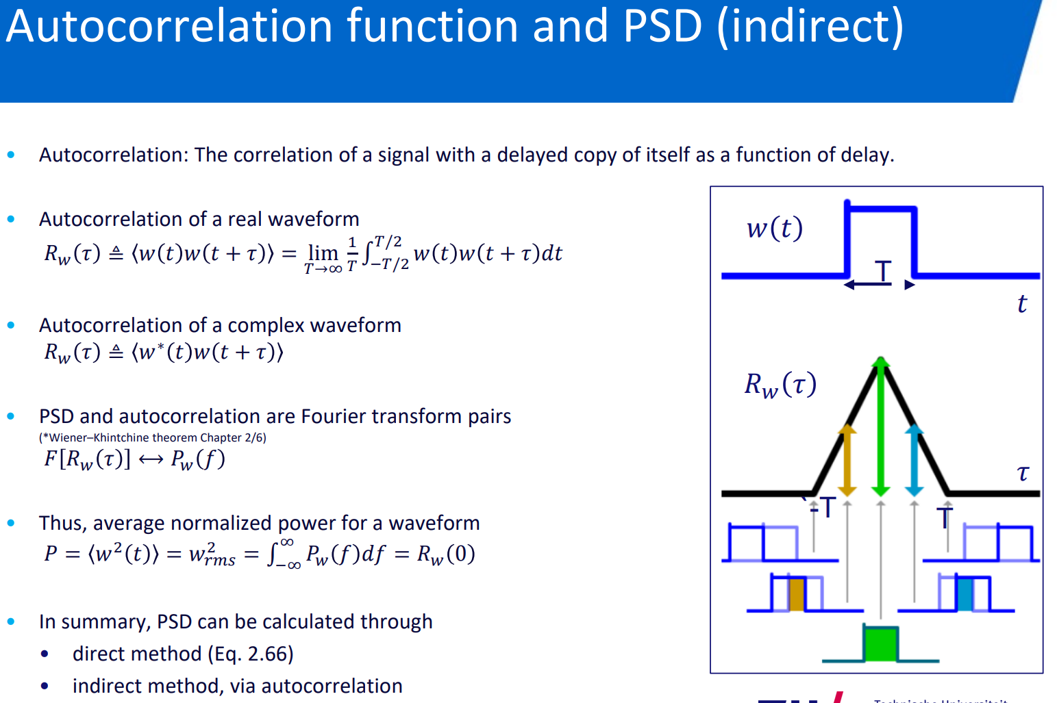
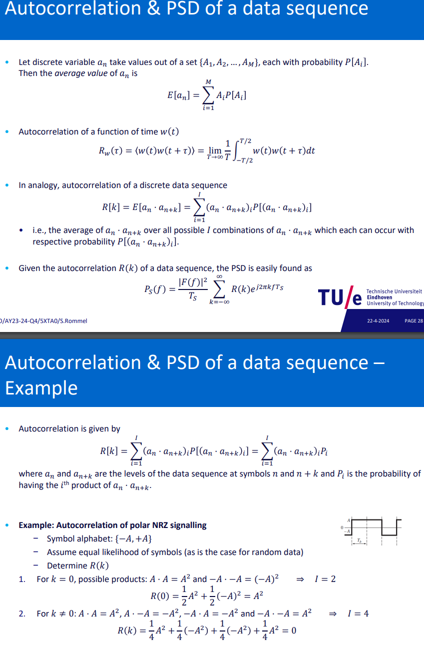
- Autocorrelation Function: Correlation of a signal with its delayed version. Crucial for PSD.
- PSD Formula:
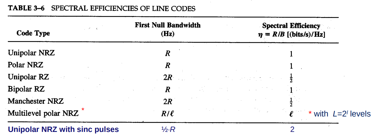
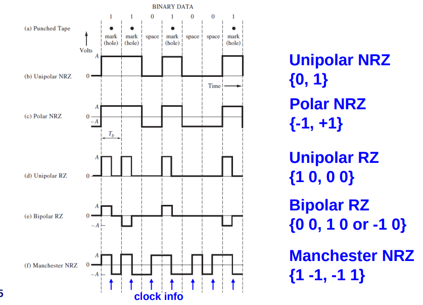
, the Fourier transform of the autocorrelation function. - Line codes transform symbols into physical waveforms, influencing performance. Types include Unipolar NRZ, Polar NRZ, Unipolar RZ, Bipolar RZ, and Manchester.
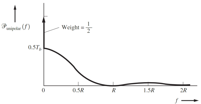
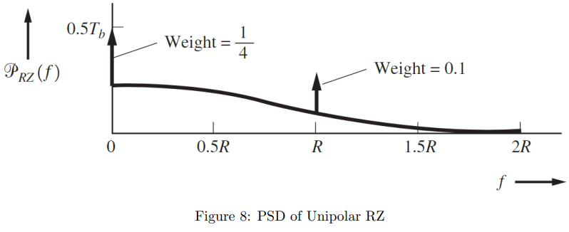
- sharp peak in PSD → DC component
Linecode Types
Differences in PSDs between line codes
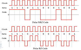
The RZ (Return to Zero) signal transmission of a logic “1” will always begin at zero and end at zero. Whereas NRZ (Non Return to Zero) signal transmission of a logic “1” may or may not begin at zero and end at zero.
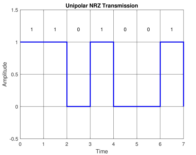
Unipolar NRZ
- Uses one power level for “1” and ground for “0”.
- PSD: Includes a DC component. Formula:
.
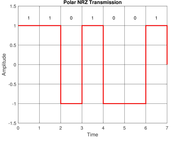
Polar NRZ
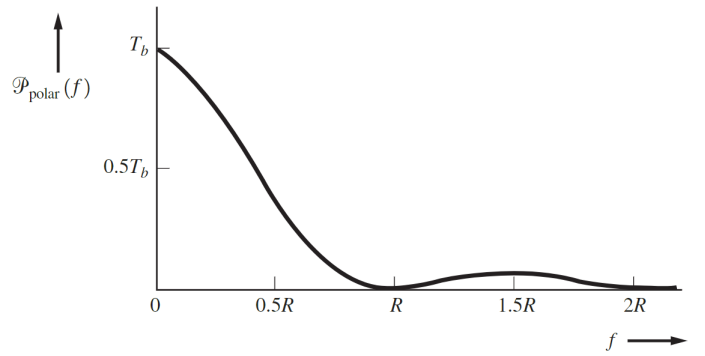
- Uses positive and negative levels for binary states.
- PSD: Lacks a DC term. Formula:
.
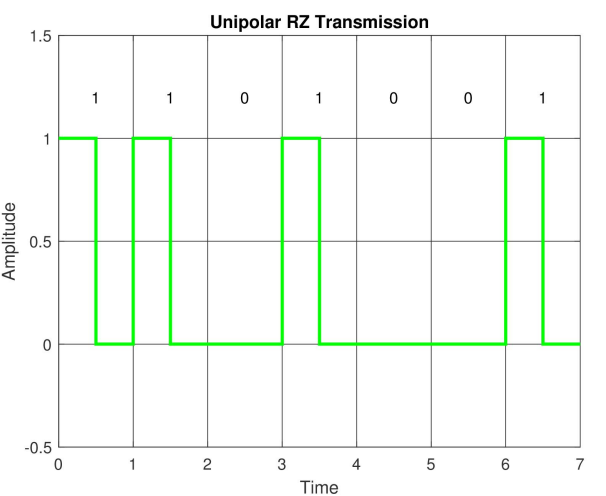
Unipolar RZ
- Returns to zero within each bit period, includes DC component.
- PSD: Formula adjusts for duty cycle.
.
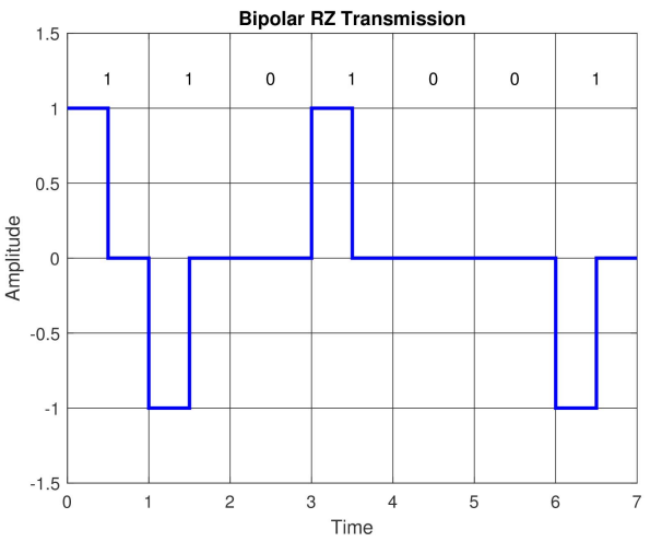
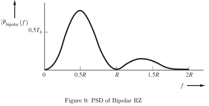
Bipolar RZ
- Alternates between positive, negative, and zero levels. No DC component.
- PSD:
.
Manchester
- Inherently synchronizes with the data stream, doubling bandwidth compared to Polar NRZ. No DC component. Behaves like a clock.
- PSD:
.
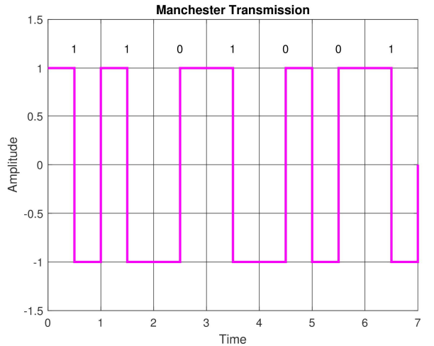
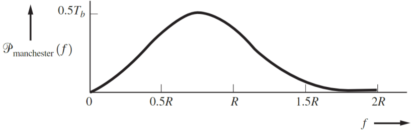
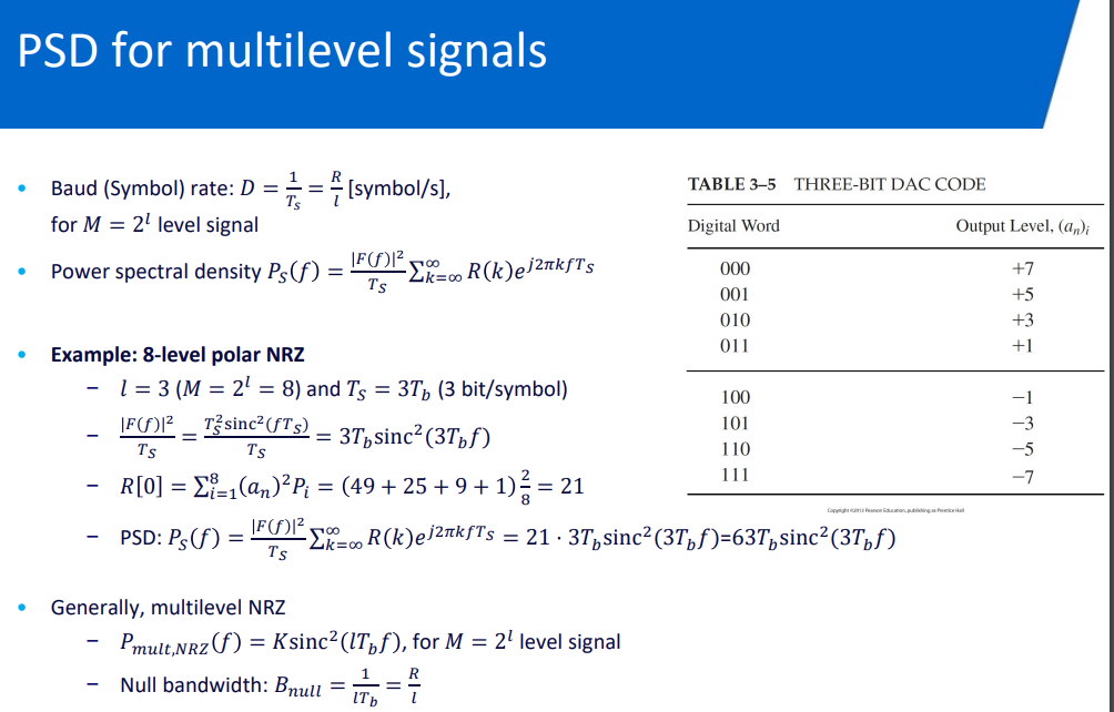
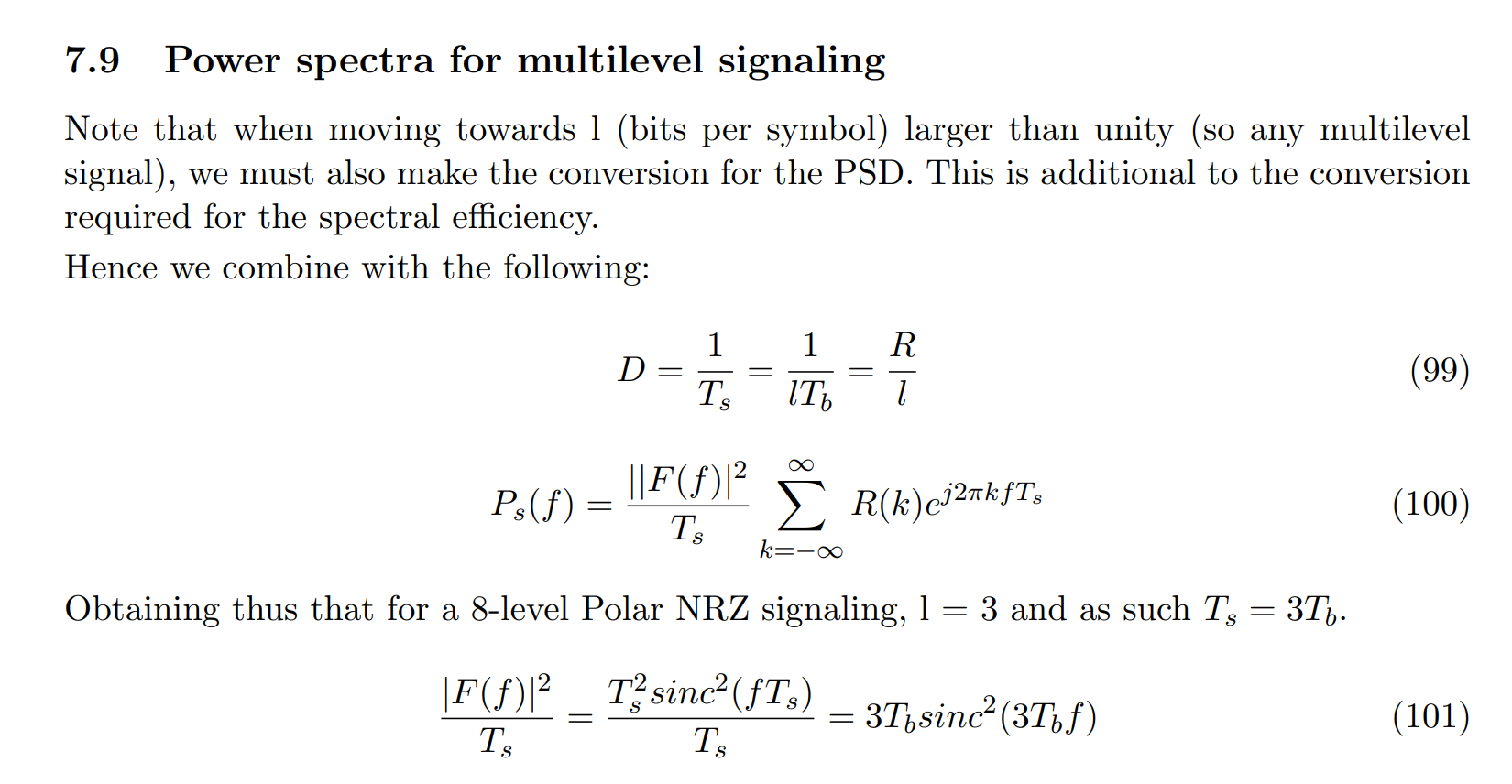
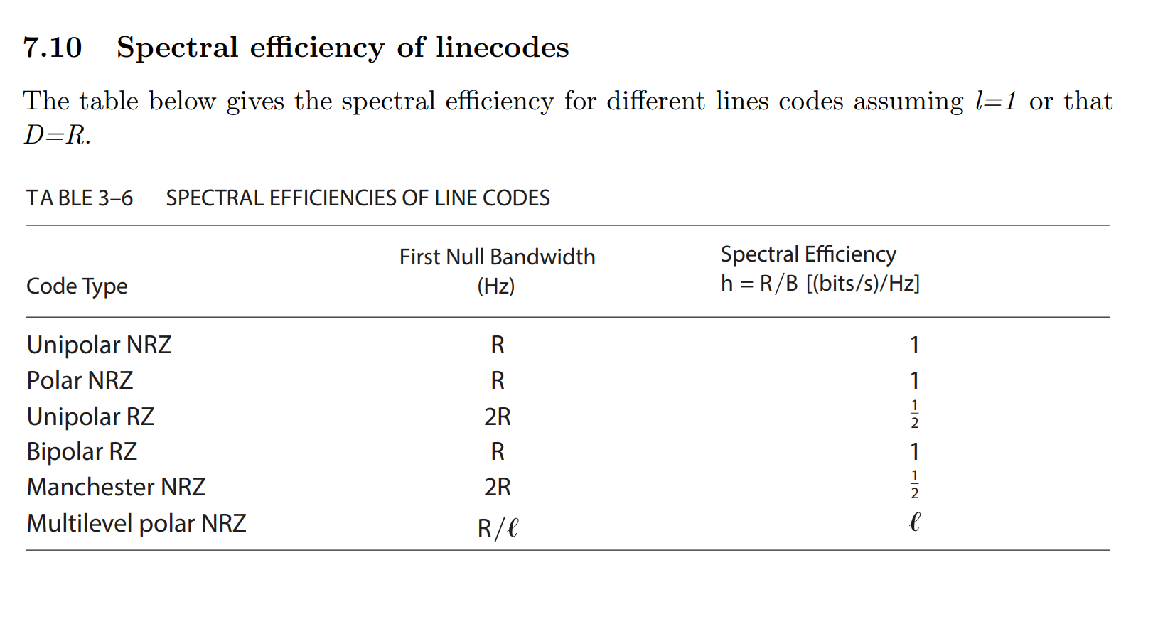
Multilevel Signaling for Multilevel Signaling and Spectral Efficiency of Linecodes
- Moving to multilevel signaling (
) affects both signal PSD and spectral efficiency. - Symbol Rate and PSD: For
, PSD adjusts to . - Spectral Efficiency: Varies with duty cycle and levels used.
any signal can be multilevel and in that case their spectral effiency is multiplied by
Inter-symbol interference
Topic: Digital Signaling and Pulse Shaping
Intersymbol interference - Wikipedia
What is inter-symbol interference?
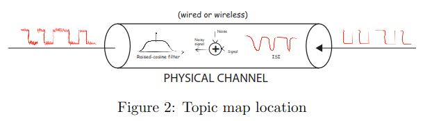
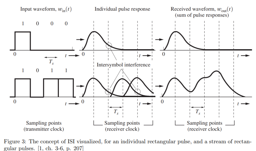
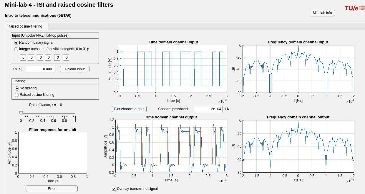
- Inter-Symbol Interference (ISI): Overlapping of signals in a communication channel, corrupting information. (smearing into other timeslots).
- Cause: Bandwidth limitations (channel passband) of channel smooth rectangular pulses, spreading them in time. (frequency attenuated → time domain less rectangular).
- Prevention: equalization techniques, proper pulse shaping, controlled bandwidth.
Modelling ISI

The baseband model of a digital signaling system is given by
Nyquist’s first method (Zero ISI)
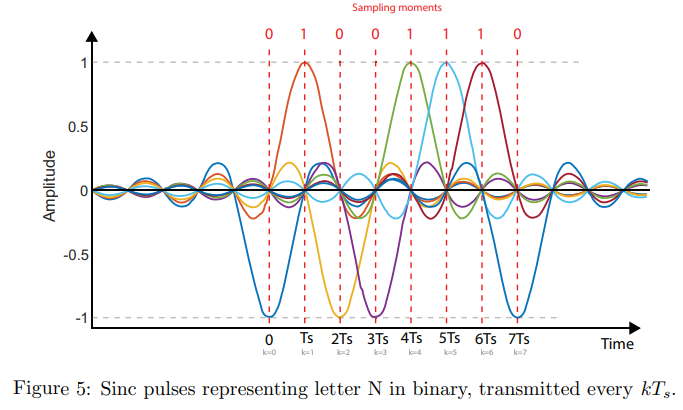
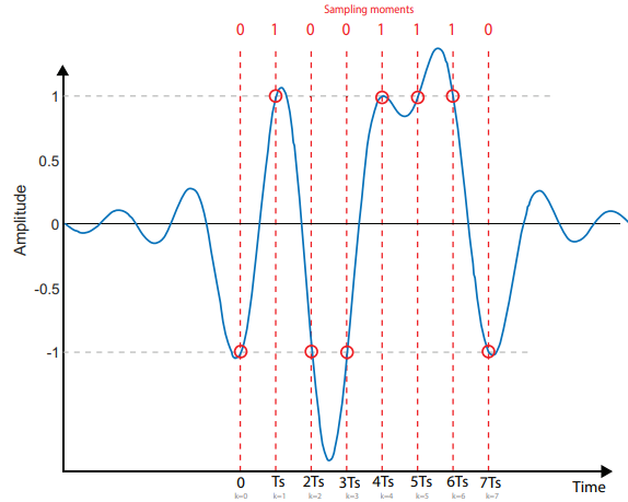
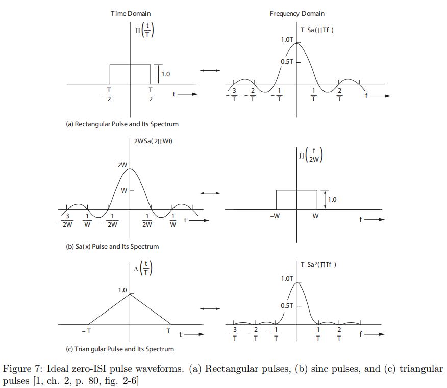
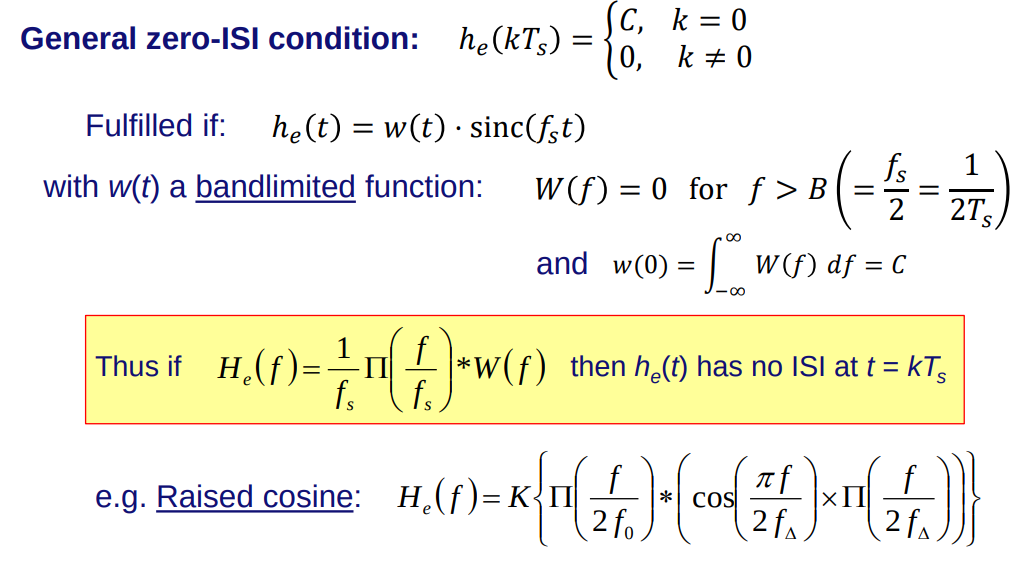
Nyquist’s First Criterion for zero ISI suggests that ideal sinc pulses, which are non-zero only at designated timeslots, can eliminate ISI completely. However, practical implementation faces challenges due to the infinite bandwidth or time domain requirements of such pulses. Raised cosine spectrum (RACOS) filtering emerges as a realizable method to minimize ISI within practical bandwidth constraints.
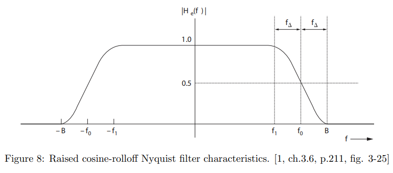
Raised cosine-rolloff Nyquist filtering (one of zero isi filters)
Topic: Filters
-
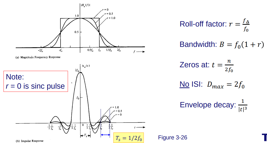
Raised Cosine-Rolloff Filtering: Minimizes ISI, customizable rolloff factor
(more bandwidth). -
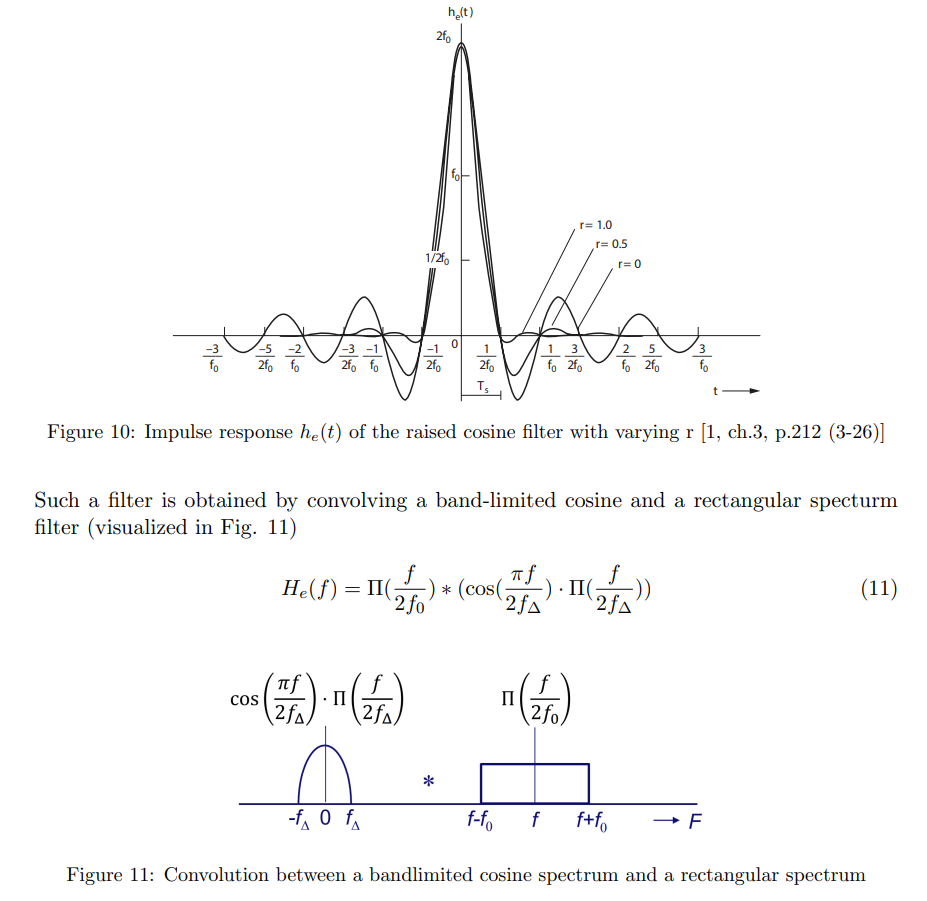
Transfer Function:
. -
Parameters:
, , Rolloff , . -
Bandwidth:
. -
Ideal for Bandlimited Channels: Reduces pulse spreading, fits channel bandwidth.
-
Time-Domain Pulse:
. -
Max Symbol Rate (No ISI):
. -
-
Practical Application: Transmits data through bandlimited channels with minimal distortion.
-
-
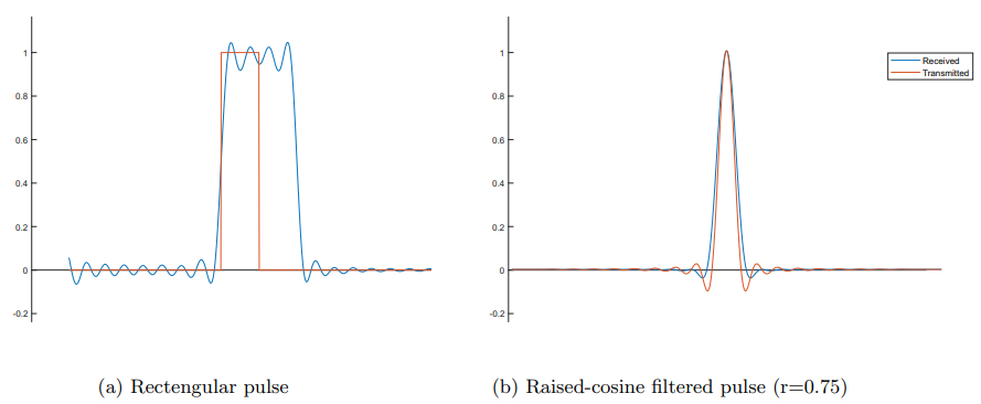
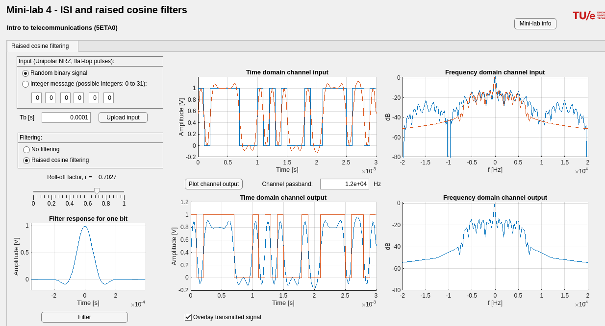
eg: When sending a square pulse with a bandwidth exceeding the channel’s maximum rated bandwidth, higher frequency components are attenuated, causing pulse spreading, interfering in adjacent time slots and oscillations
-
To address this, on the otherhand sending a raised-cosine filtered pulse with a 0.75 roll-off factor, fitting the channel’s bandwidth, results in significantly reduced pulse spreading
Information Theory
Topic: Channel Capacity
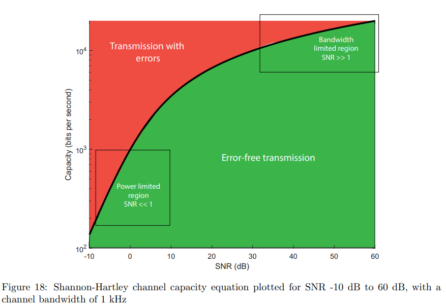
Shannon–Hartley channel capacity theorem
SNR NOT IN dB
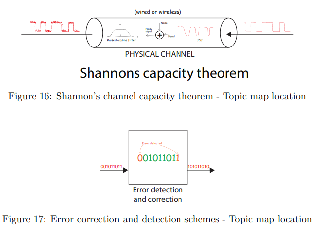
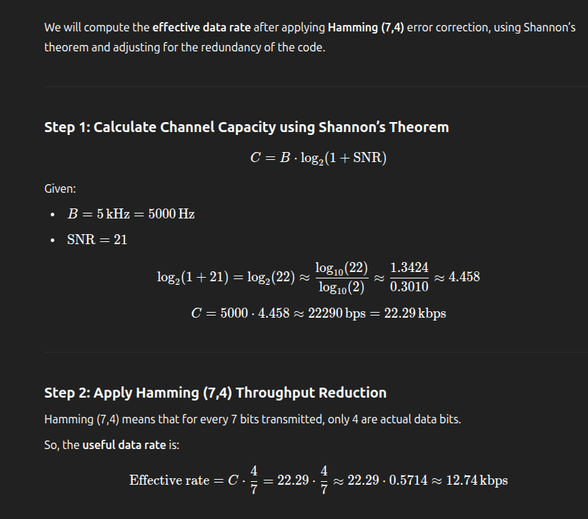
- Shannon-Hartley Theorem:
[bits/s], defines max information rate . - Max Spectral Efficiency:
[bits/s/Hz], efficiency of bandwidth usage. - Power-Limited Region: Low SNR (
), capacity increases with SNR. - Bandwidth-Limited Region: High SNR (
), capacity constrained by bandwidth, not SNR.
Error detection and correction schemes
Topic: Networks and Error Control
Hamming code - Wikipedia
But what are Hamming codes? The origin of error correction - YouTube
- Parity Bit Checking: Fails with multiple bit flips, only detects odd number of errors.
- Hamming Codes: Enables both error detection and correction.
- Hamming Code Structure:
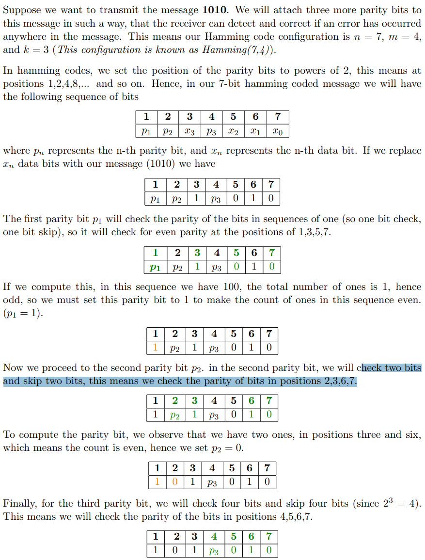
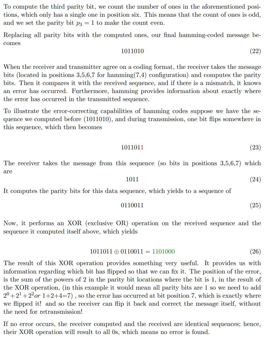
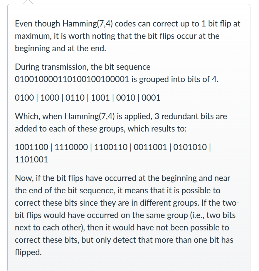
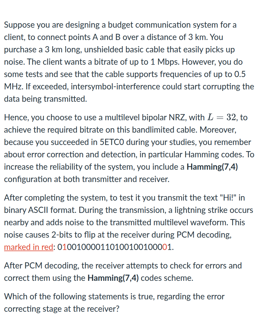
, = data bits, = parity bits. - Hamming(7,4) Example: Adds 3 parity bits to 4-bit message, corrects single bit error. CAN CORRECT 1 ERROR BIT PER MESSAGE IF THERE IS 24 BIT STRING AND WE HAVE 7/4 MEANS IT CAN CORRECT 1 BIT IN BITS OF 7 SO UP TO 3 IN WHOLE STRING
- Parity Bit Positions: Set at powers of 2 (1, 2, 4, 8, …).
- If there s 1 flip it takes the output gets the message bits, does a parity check then performs XOR operation on it with the flipped sequence, calculates finds the position of the flipped bit.
- Limitations of Hamming: Corrects 1-bit errors but only detects multiple errors.
- Advanced Schemes: Modern systems use LDPC, polar codes for better error correction.
Amplitude, Frequency and Phase Modulation
Topic: Modulation
Pulse-code modulation - Wikipedia
Amplitude modulation - Wikipedia
Frequency modulation - Wikipedia
SEE INSTRUCTION 8 AND 9
Main
- dBm is an absolute power level (referenced to 1 mW).
- dB is a relative ratio between two power levels.
What is Modulation ? Why Modulation is Required ? Types of Modulation Explained. - YouTube
Amplitude Modulation – Physics and Radio-Electronics
-
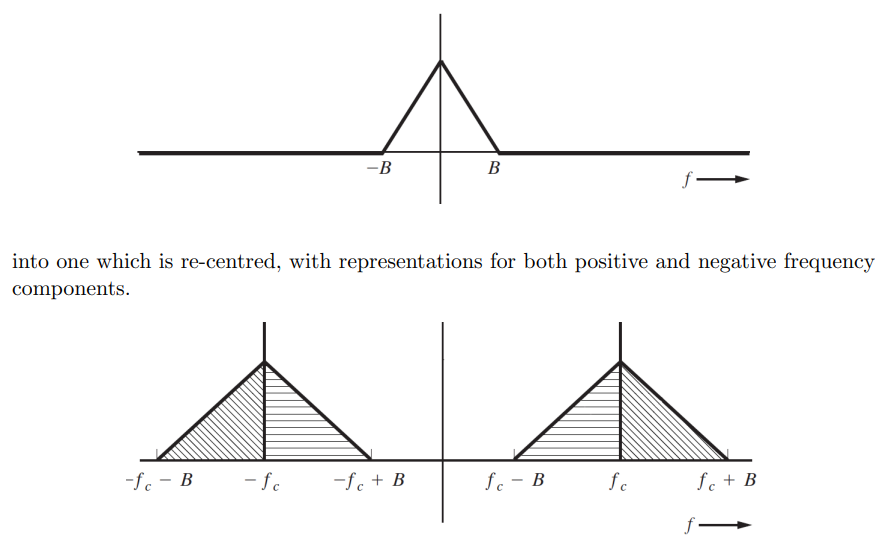
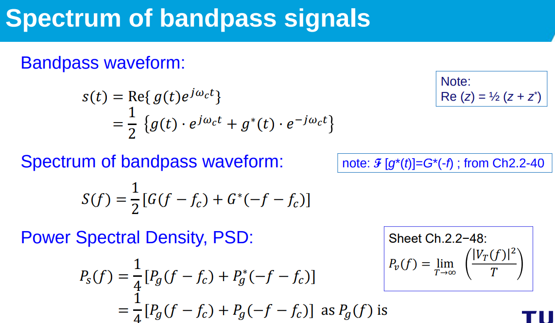
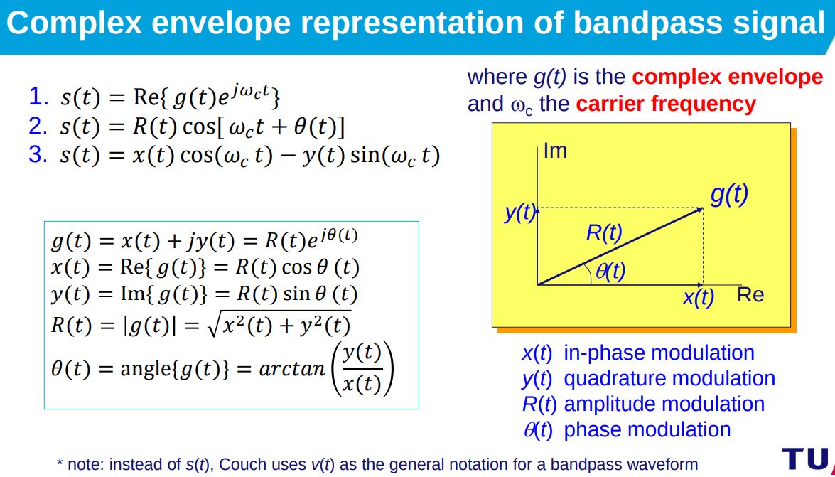
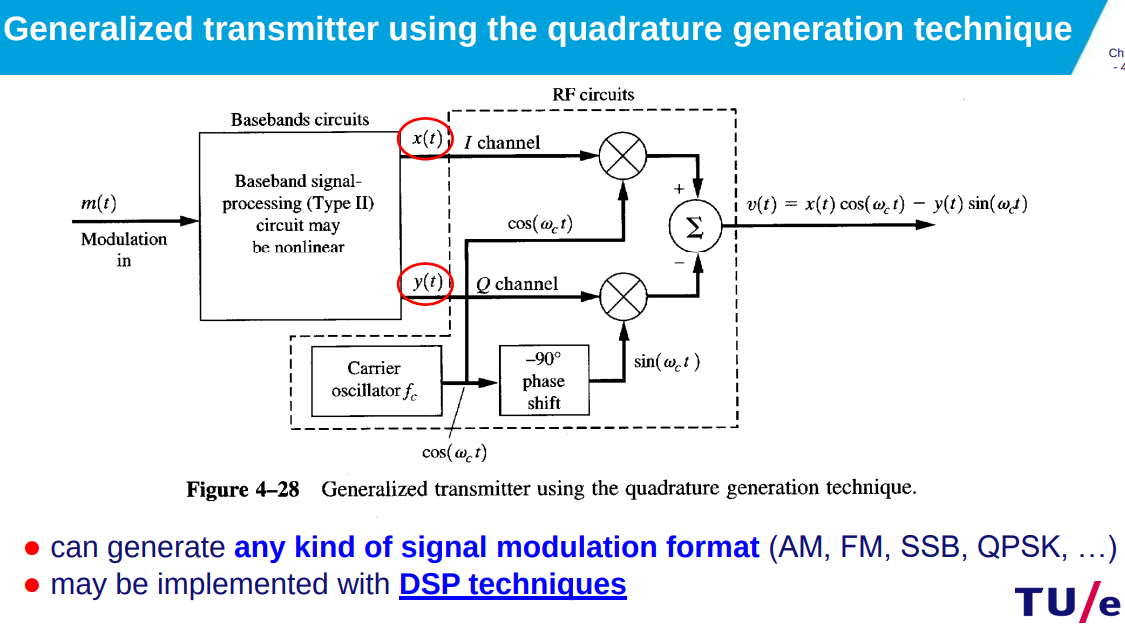
Baseband(when frequency spectrum irrelevant) vs. Bandpass(eg: for open air transmisison) (spectrum of signal): Baseband centered at 0Hz, Bandpass re-centered to carrier frequency for open-air transmission.
-
Baseband transmission sends the information signal as it is without modulation (without frequency shifting) while passband transmission shifts the signal to be transmitted in frequency to a higher frequency and then transmits it, where at the receiver the signal is shifted back to its original frequency.
-
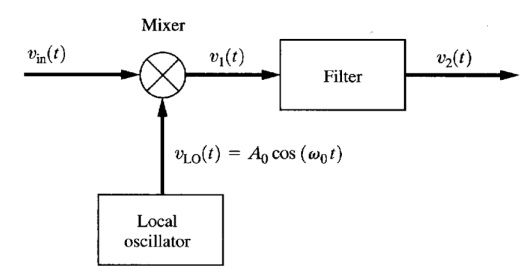
Upconversion: Shifts baseband to bandpass via mixer, enabling transmission on specific frequencies.
-
Downconversion: Mixer(circuit) reverses process, extracting baseband from received bandpass signal.
-
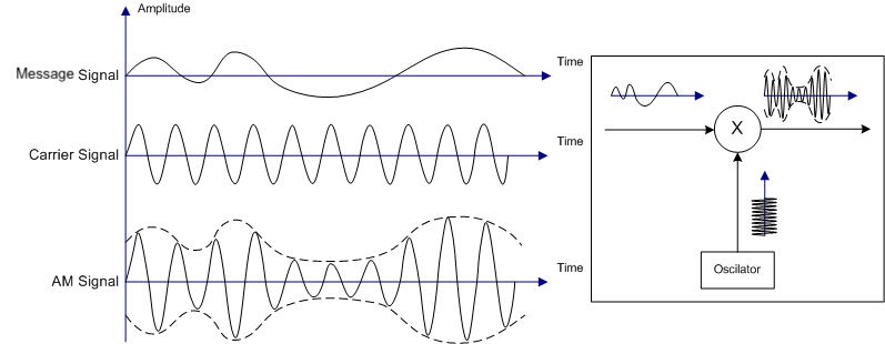
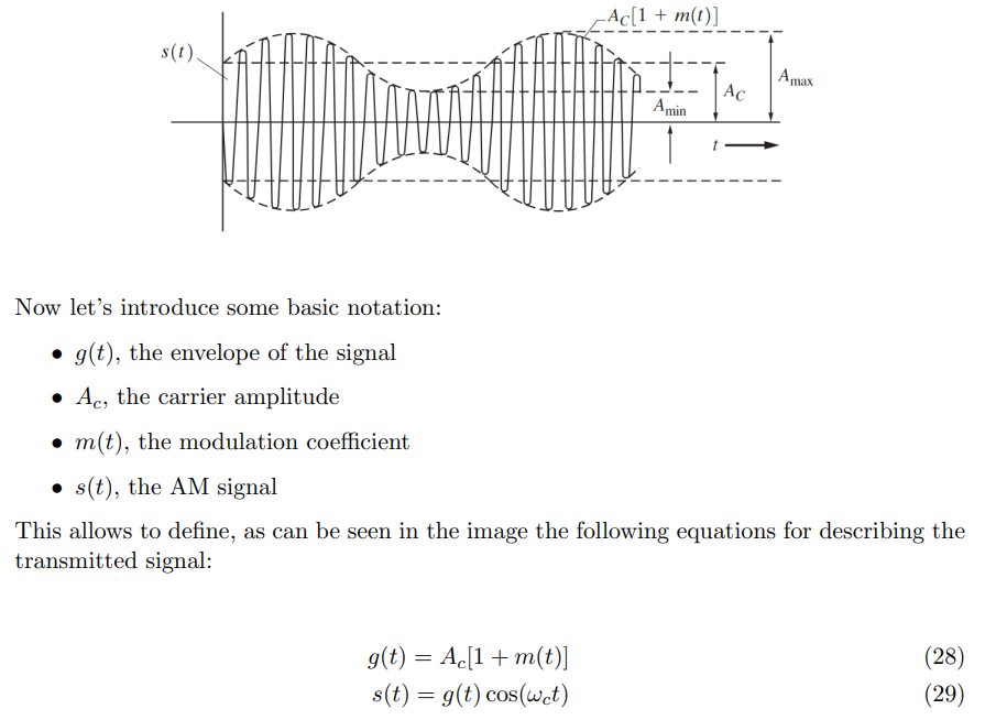
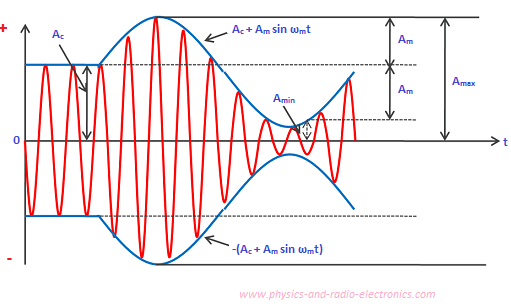
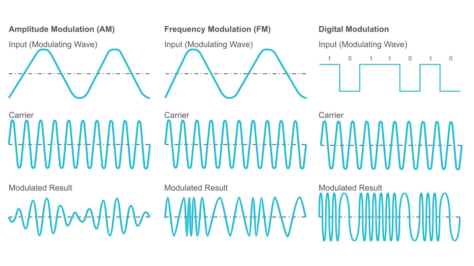
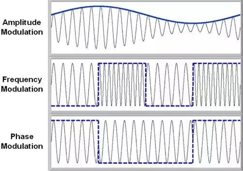
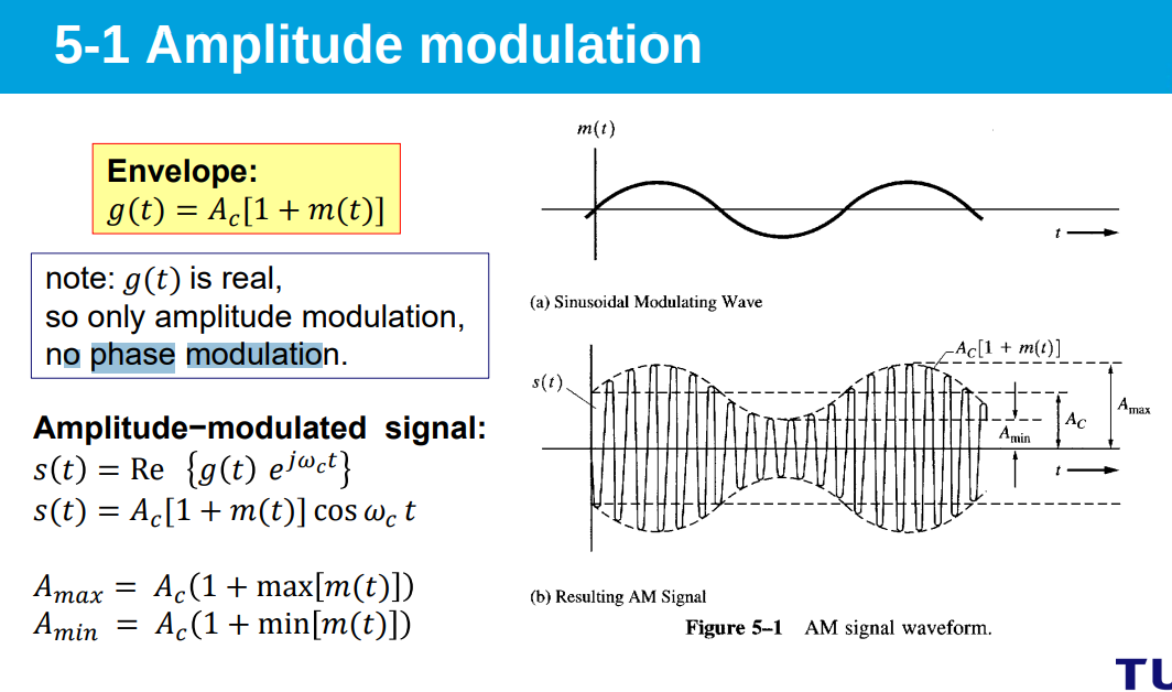
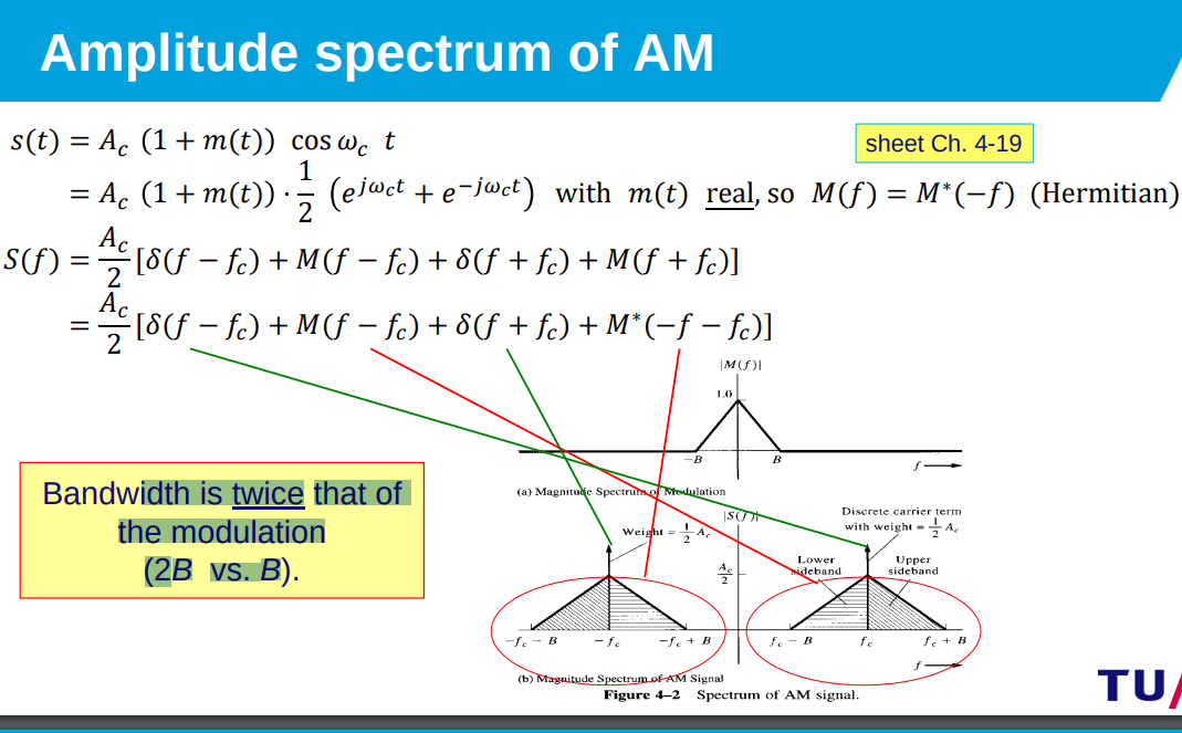
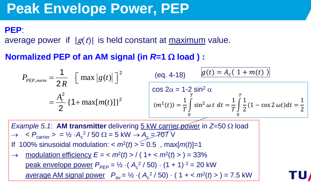
Amplitude Modulation (AM): Encodes input signal information in carrier amplitude.
-
-
AM Signal:
, where = carrier amplitude, = modulation coefficient carrier signal. -
-
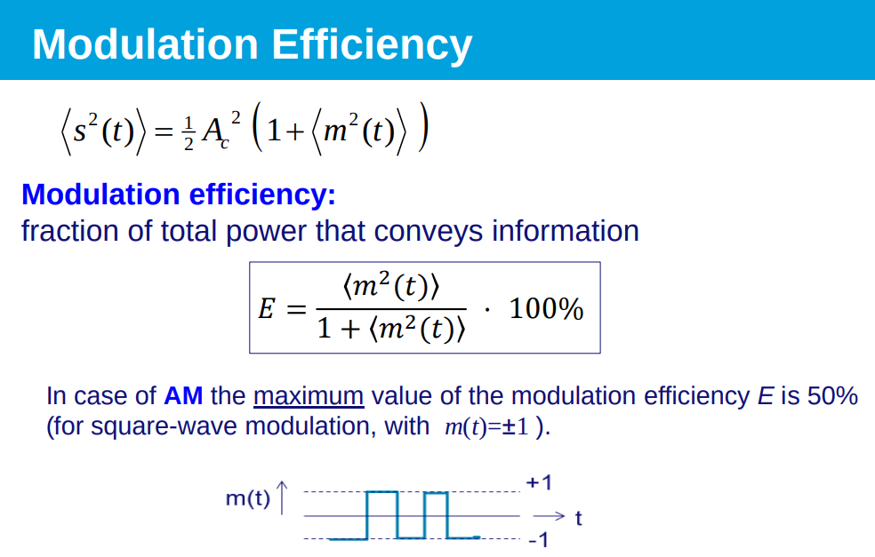
Modulation Efficiency:
for sinusoidal signals . -
for square waves its 1 not
-
-
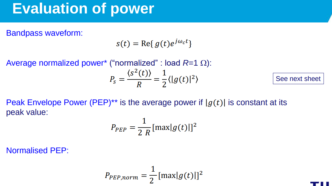
Peak Envelope Power (PEP):
, measures maximum signal power. -
Percentage of Modulation:
, indicates modulation depth for . -
-
-
-
Amplitude Modulation Waveform and Equation | Communication System - YouTube
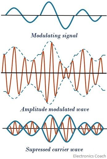
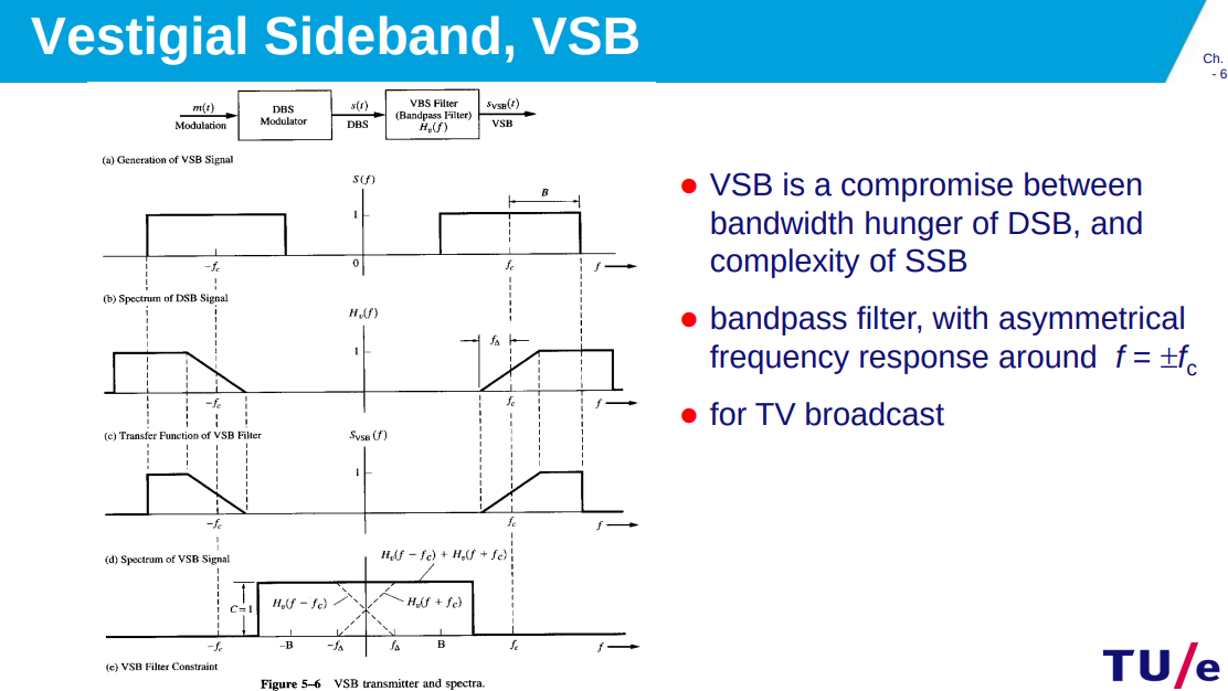
DSB-SC - Double-Sideband Supressed Carrier - type of AM modulation
Introduction to Amplitude Modulation | Double Side Band Suppressed (DSB-SC) Carrier Explained - YouTube
Double-sideband suppressed-carrier transmission - Wikipedia
Sideband - Wikipedia
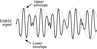
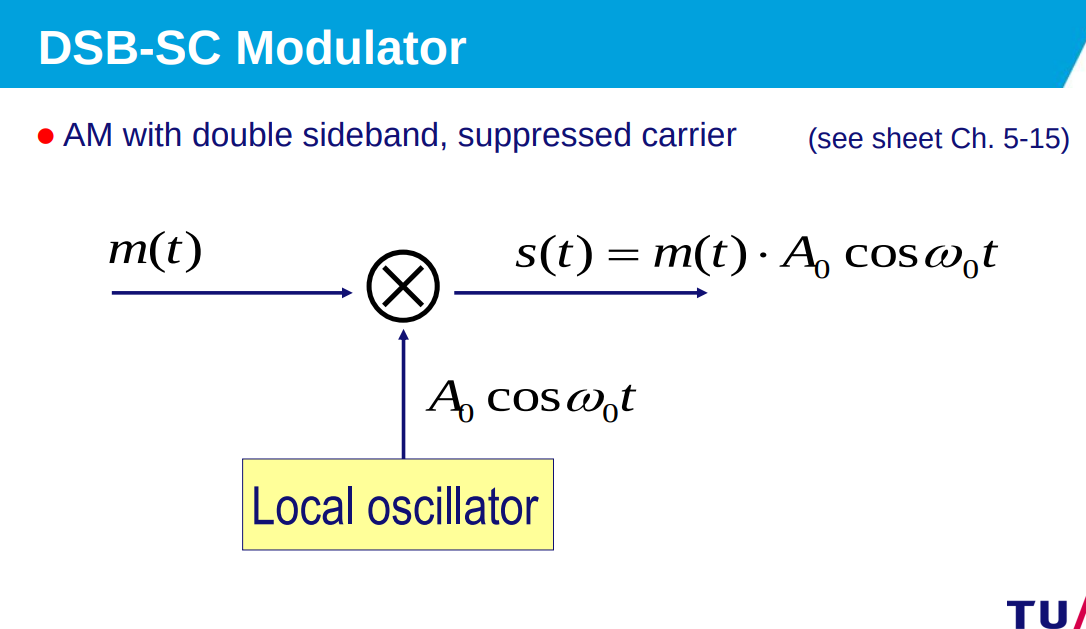
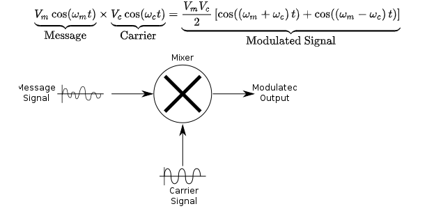
- Signal Representation:
. - Envelope and Carrier:
. - Modulation Efficiency: 100% due to absence of carrier.
- Percentage of Modulation: Infinite, as carrier is suppressed.
- Double-sideband suppressed-carrier transmission (DSB-SC) is transmission in which frequencies produced by amplitude modulation (AM) are symmetrically spaced above and below the carrier frequency and the carrier level is reduced to the lowest practical level, ideally being completely suppressed.
Detector circuits
AM Demodulation - Envelope Detector Explained (with Simulation) - YouTube
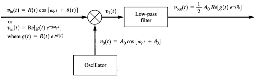
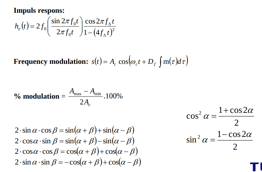
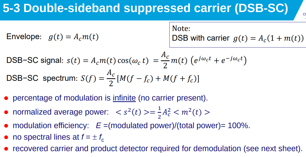
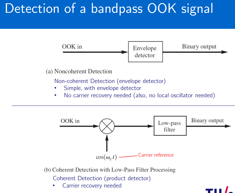
- Detector Circuits: Decode information from waveform; crucial for demodulation.
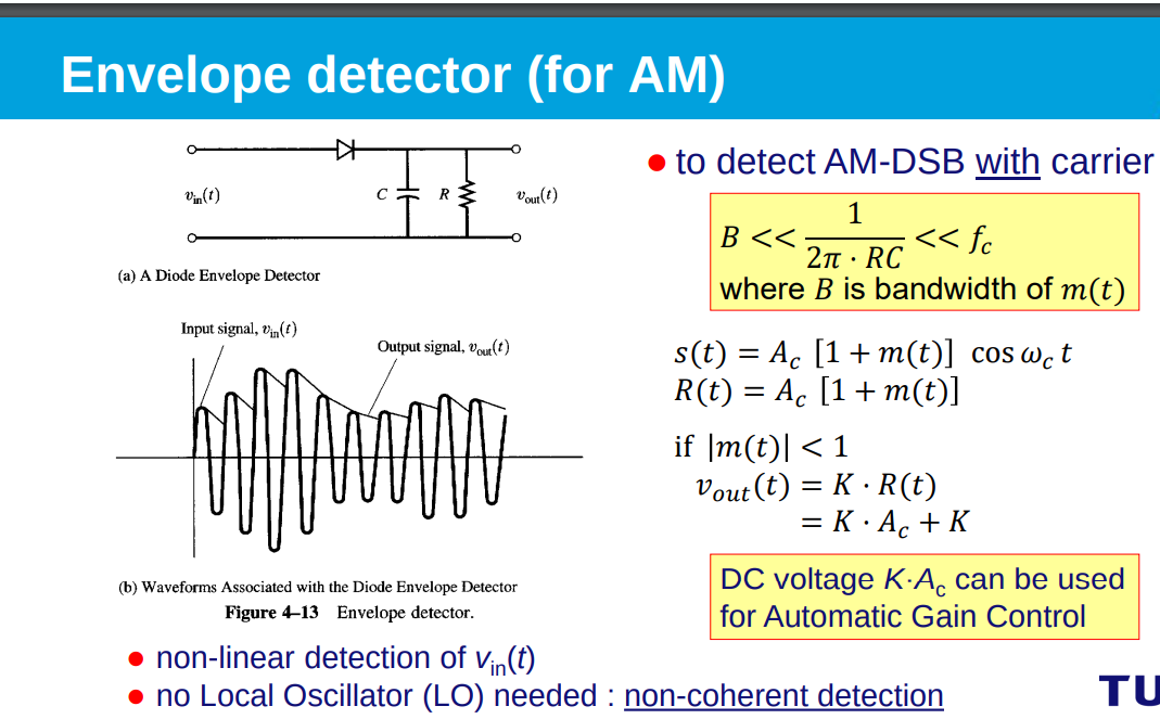
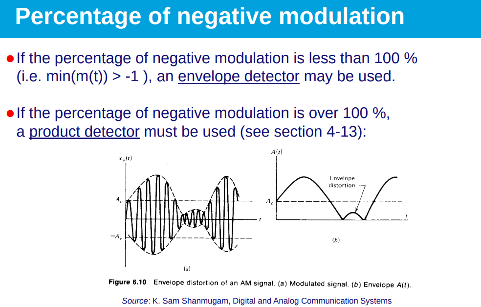
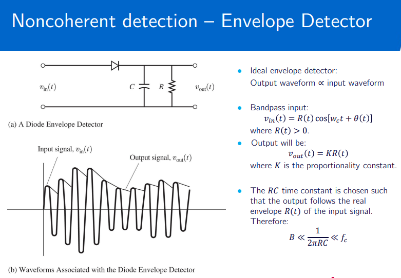
- Envelope Detector: Simple, passive devices; ideal for AM signals with positive modulation under 100%.
- Drawbacks: Fails with negative modulation >100%; not suitable for all modulation types.
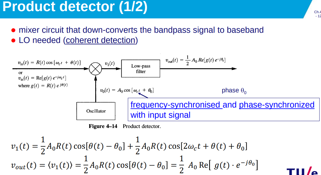
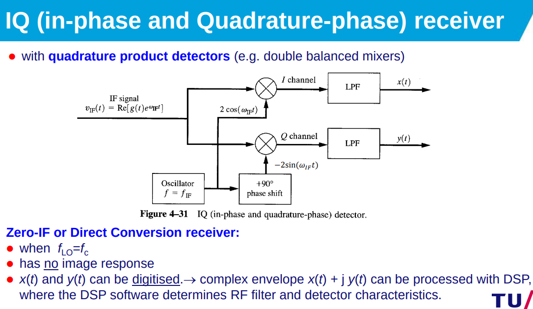
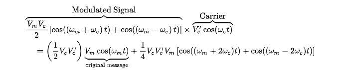
- Product Detector: Demodulates AM and PM; uses local oscillator for downconversion to baseband. allows for %mod > 1 (where LO (local oscillator) has same frequency and phase as carrier).
- Phase Detection: Works as a phase detector with sinusoidal characteristic; versatile for AM/PM signals.
Frequency and Phase Modulation
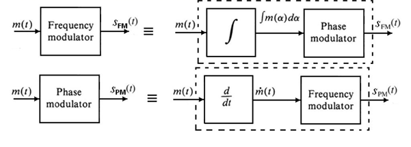
FM (Frequency Modulation)
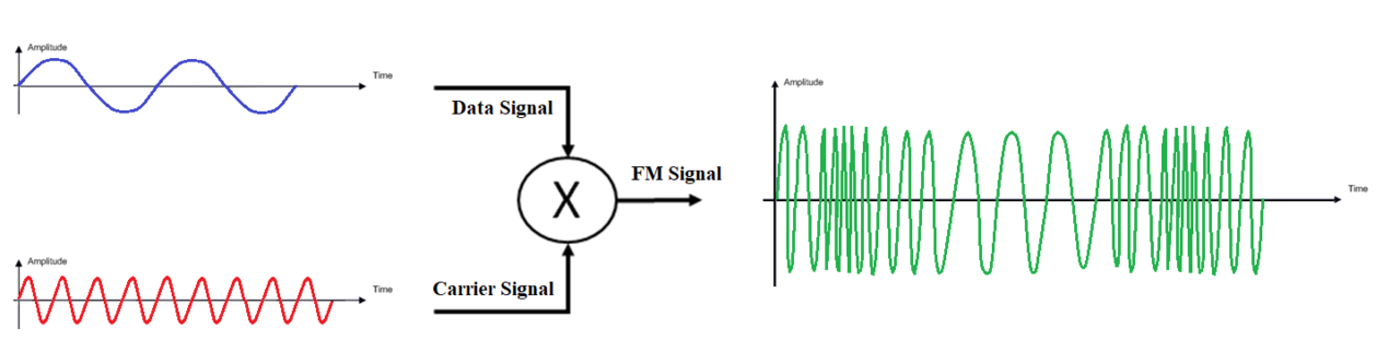
- Encodes information in signal frequency, amplitude remains constant.
- Higher fidelity than AM due to frequency-based encoding.
- FM & AM:
constant, linear func of , nonlinear func of
PM (Phase Modulation)- Encodes information directly into signal phase.
Frequency and phase deviation
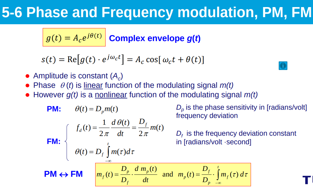
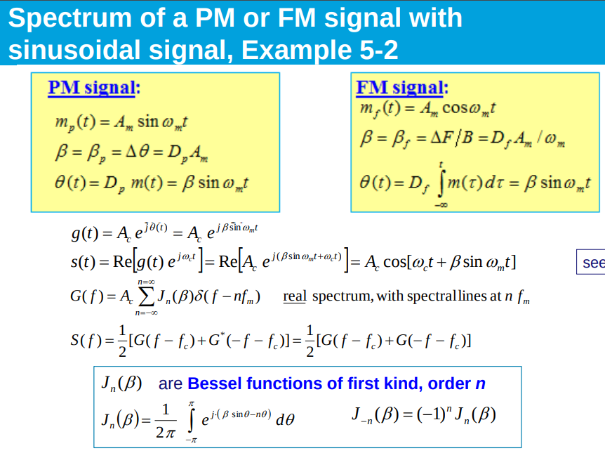
- Peak Frequency Deviation:
; measures max frequency change. - Frequency Modulation Index:
; ratio of peak deviation to bandwidth. - Peak Phase Deviation:
; measures max phase change. - Phase Modulation Index:
; indicates extent of phase variation.
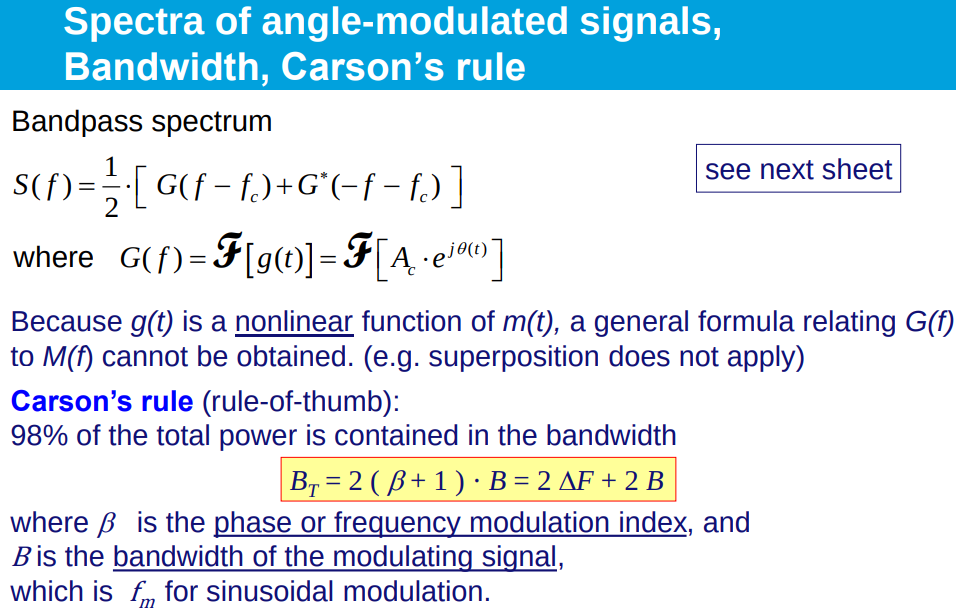
Carson’s rule
- Carson’s Rule: Estimates bandwidth containing 98% of total power for FM/PM signals.
- Total Bandwidth (BT):
; = modulation index, = modulating signal bandwidth.
Frequency spectrum of FM and PM
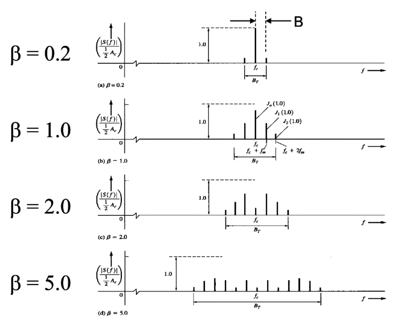
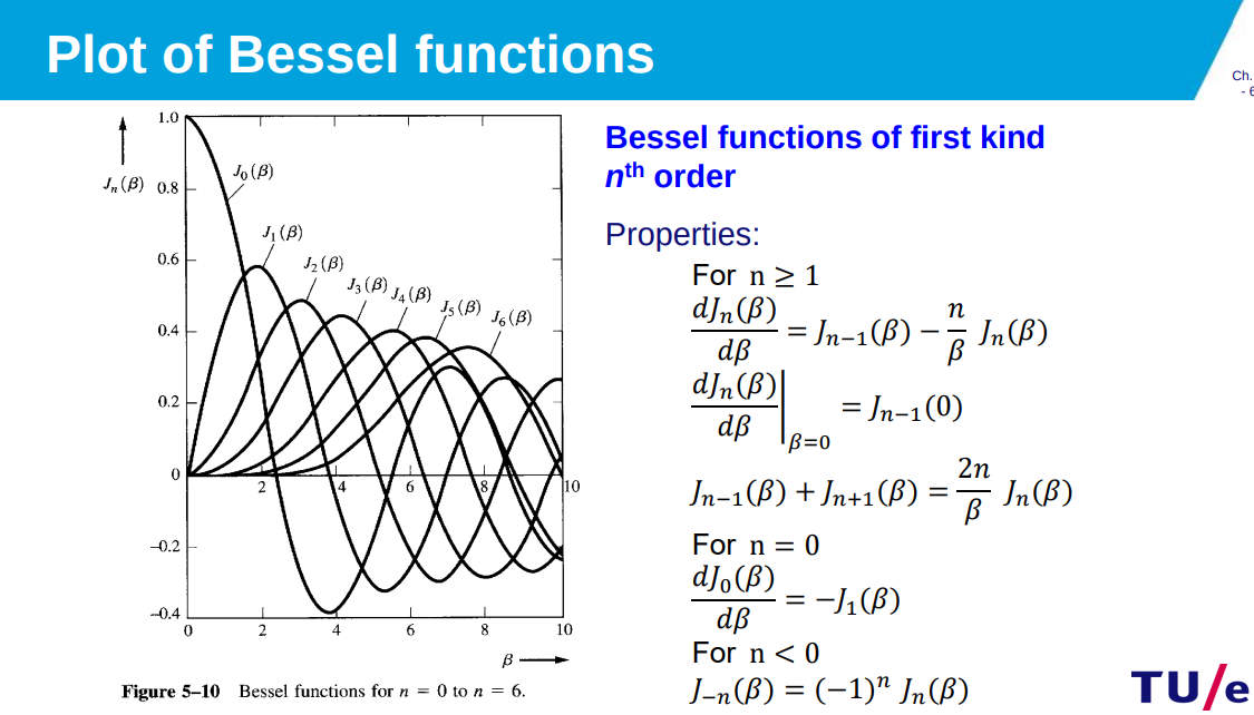
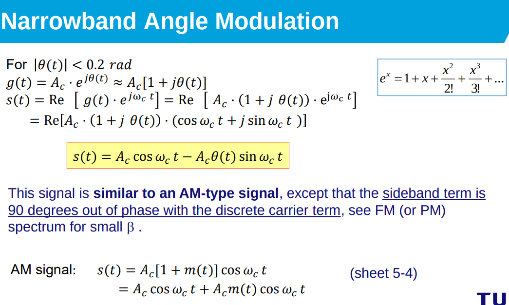
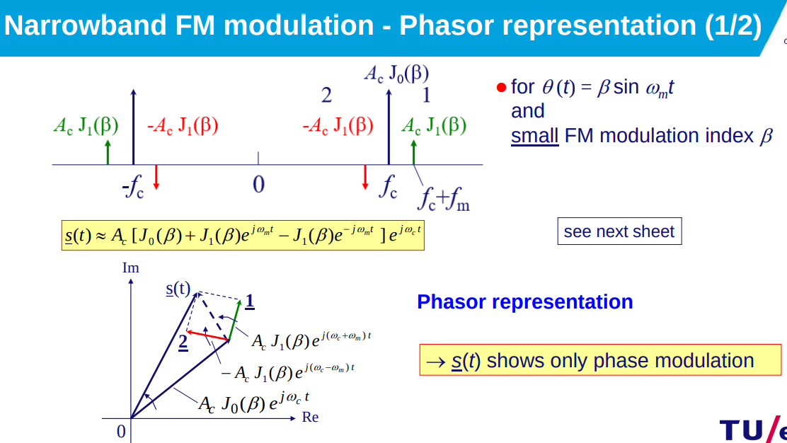
Represents signal in the frequency domain, where the spectrum is a sum of Bessel functions.
- Frequency Spectrum:
. - Spectrum Conversion:
; accounts for carrier frequency shift. - Bessel Functions:
; . - Carson’s Rule Context: Links total bandwidth
with modulation index and modulating signal bandwidth .
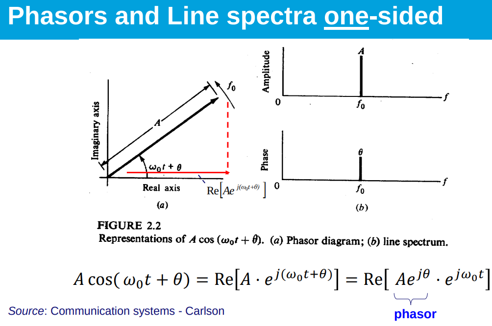
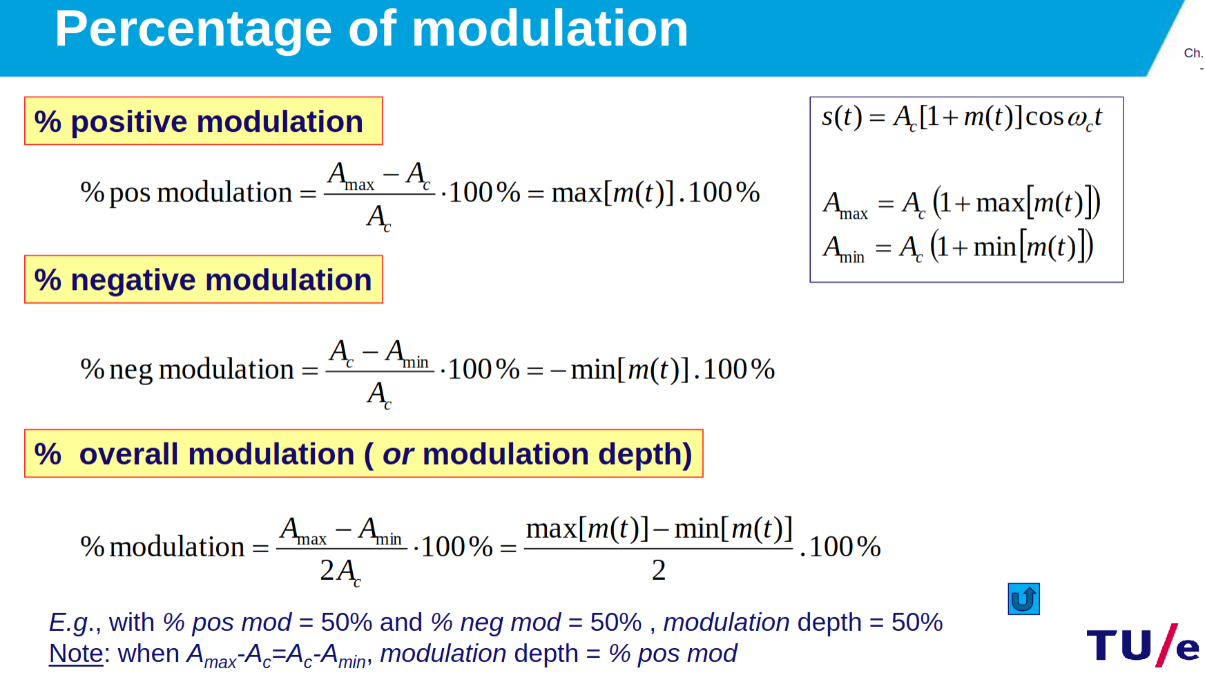
Detector Explanation
- AM Modulation: Uses carrier signal amplitude to encode information, extracted by an envelope detector for modulation percentages < 100%.
- DSB-SC: Lacks a carrier, encoding information in the amplitude variations around the carrier frequency, requiring a product detector for demodulation.
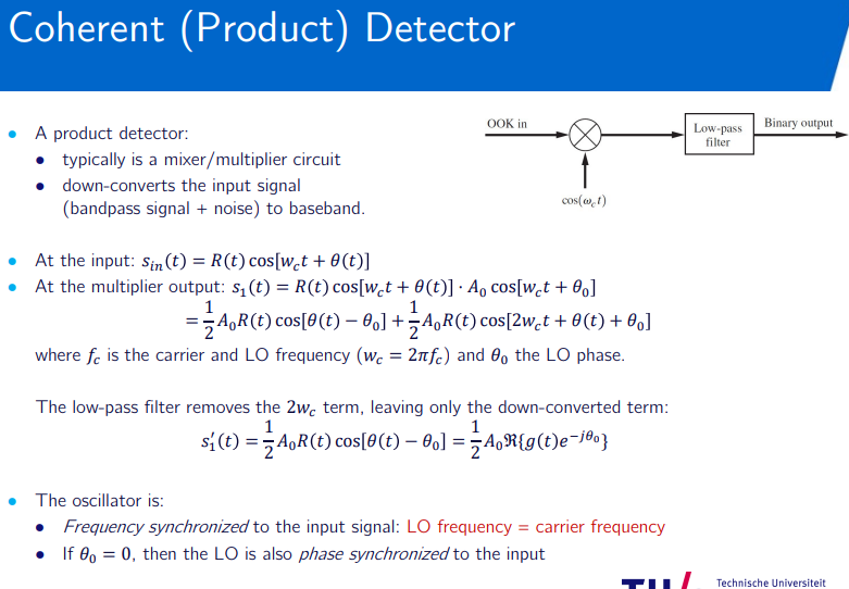
The Physical channel
Topic: Wireless Channel
Wired and wireless comparison
- radio frequency (RF) wireless channel, wired optical fiber channel
- Wired: stable, higher capacity via cables/fibers, constant delay, low BER(bit error rate) (
), high fidelity, secure, fixed, size variable, grid power, health-safe. - Wireless: dynamic, capacity via tech/cell size, variable delay, higher BER (
), lower fidelity, easily jammed/intercepted, mobile, size constrained, battery-powered, health-regulated.
Wireless channel
-
RF propagation: Power spreads equally on sphere surface; atmospheric absorption varies by frequency/humidity.
-
Free space propagation:
single path -
omnidirectional antenna gain:
-
-
Friis equation for gain:
. -
Logarithmic scale power:
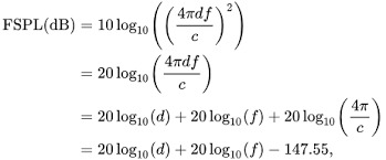
multi path -
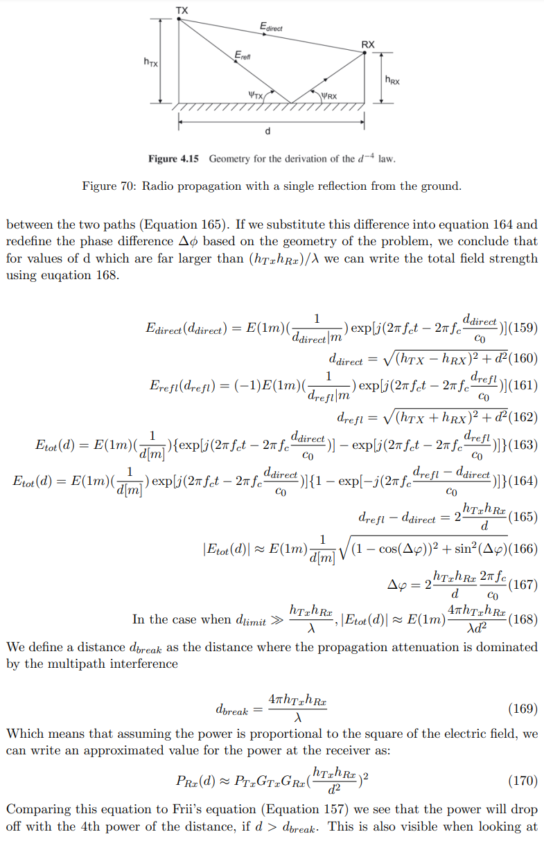
Single reflection from ground causes phase difference, affecting signal at receiver.
-
Total electric field at receiver (
) combines direct and reflected signals. -
Path length difference:
. -
Total field strength for large
: . -
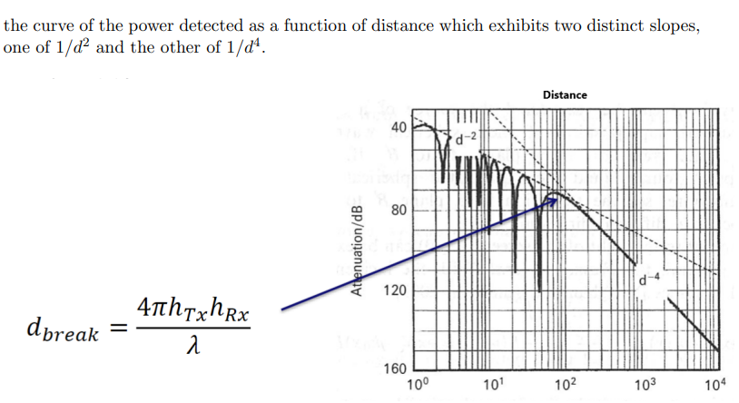
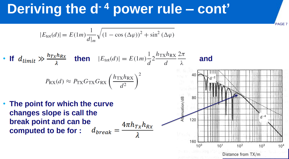
Break distance (
) where multipath dominates: . -
Power at receiver for
: , showing rule.
-
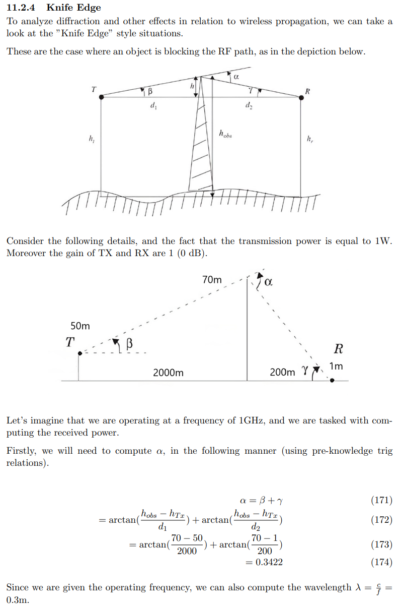
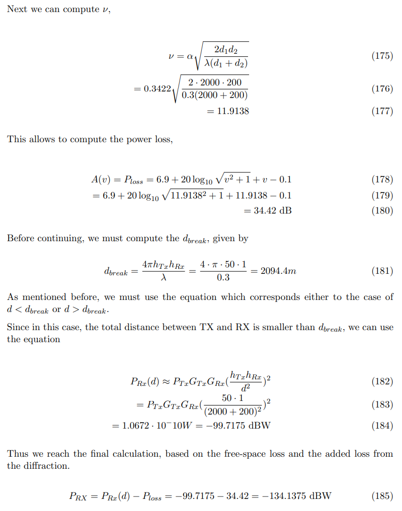
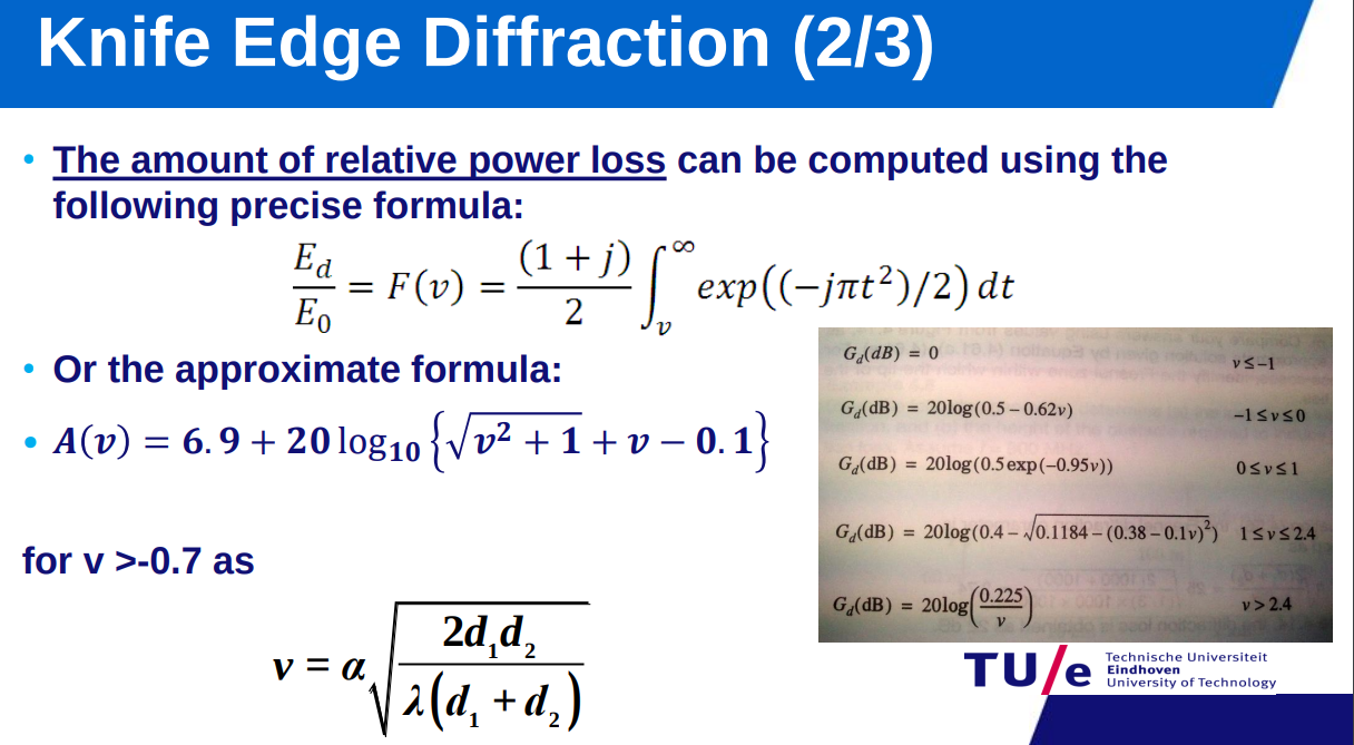
Knife Edge: Diffraction causes additional power loss;
for object blocking path. for -
-
-
-
knife edge is worse when you are closer to the obstacle…
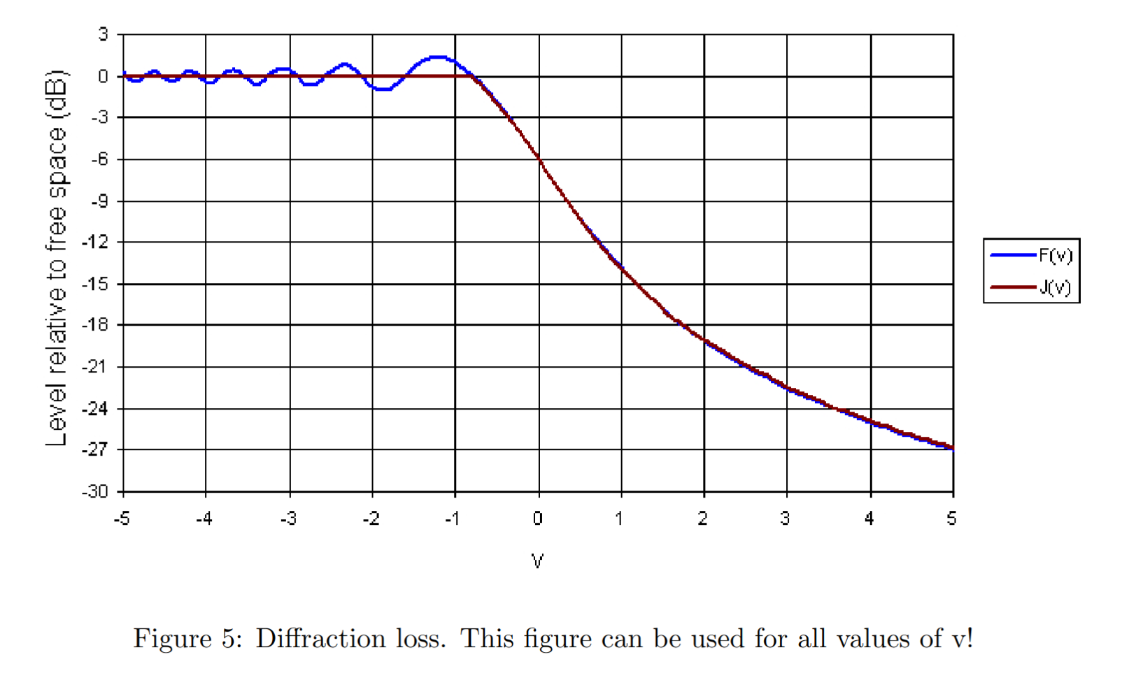
when positive it means loss =
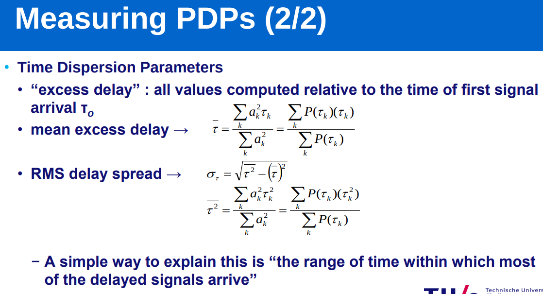
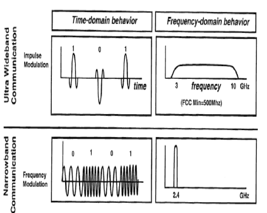
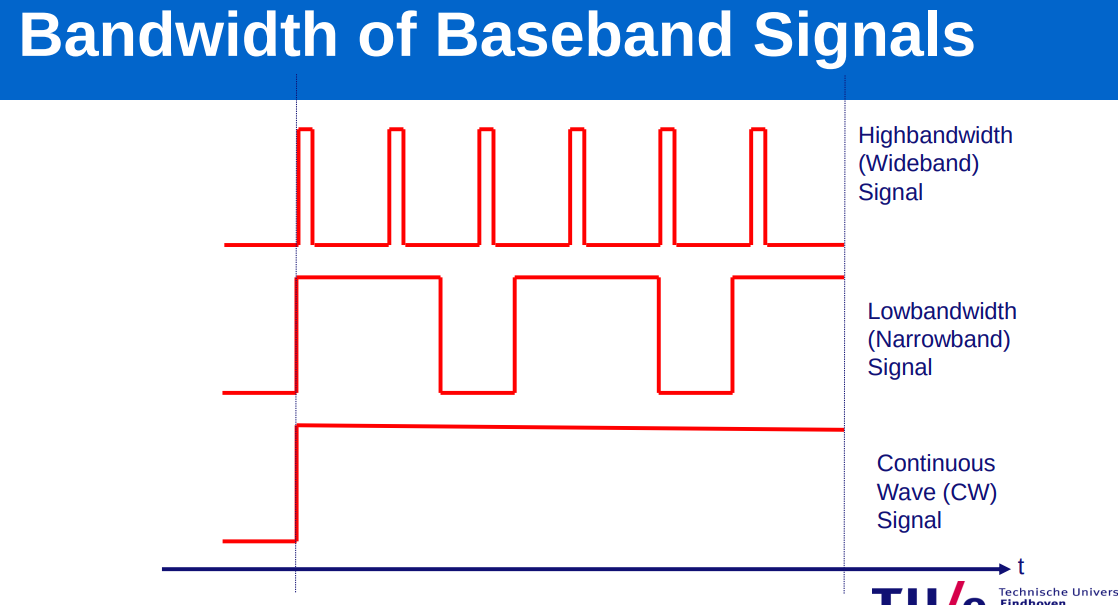
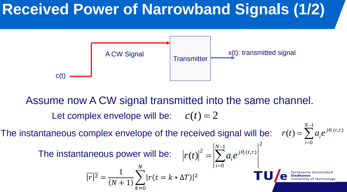
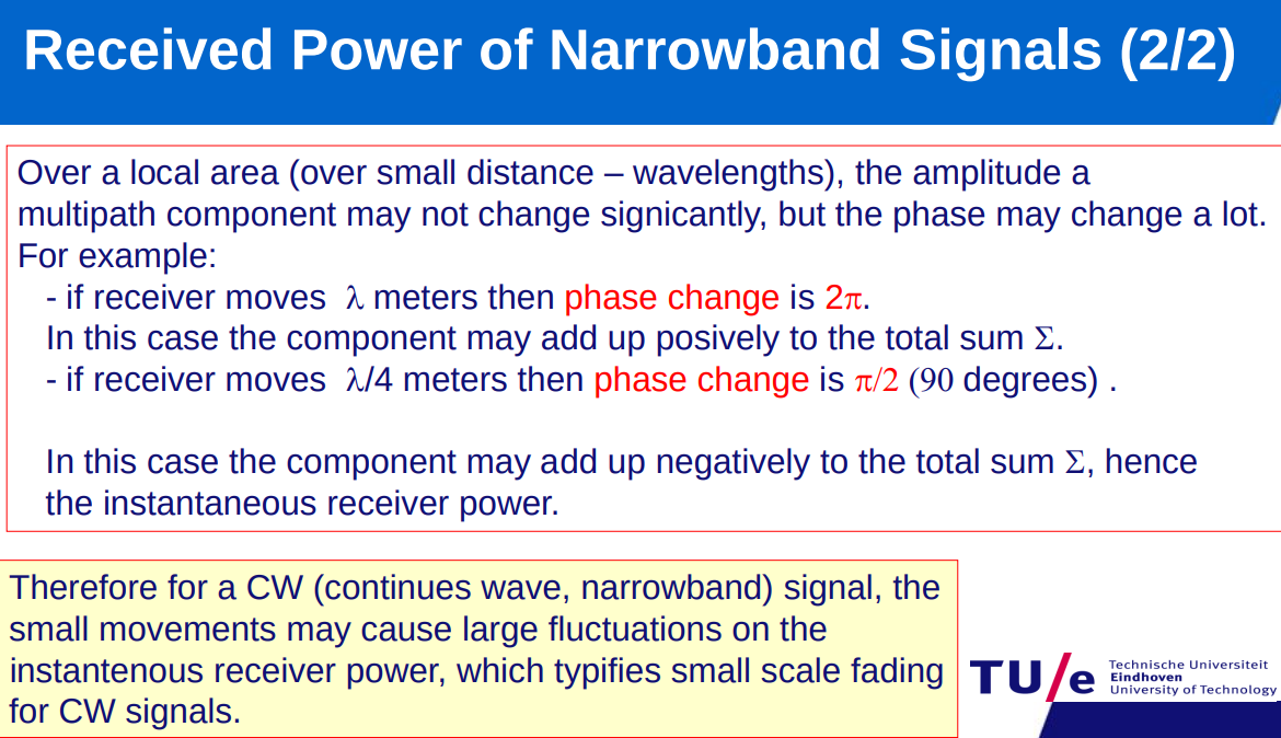
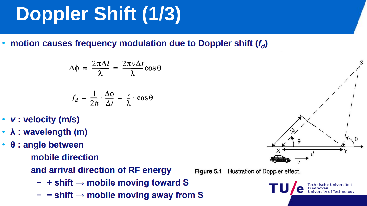
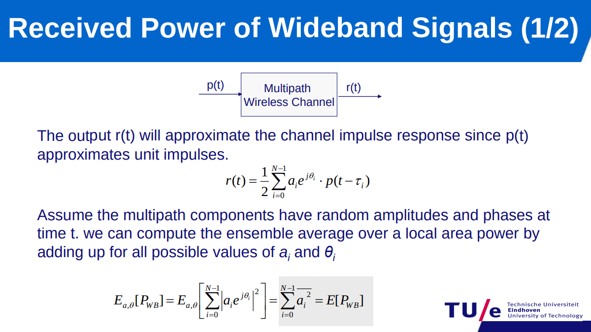
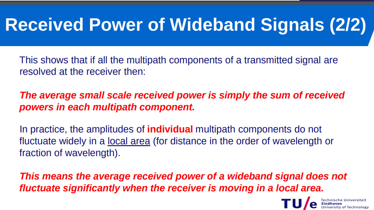
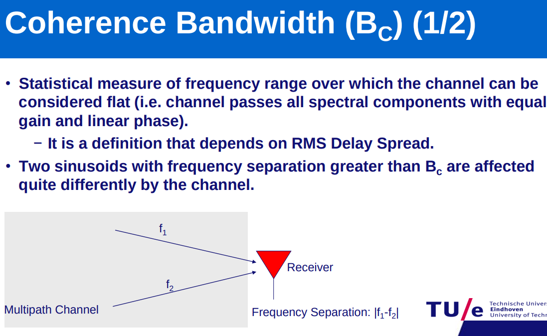
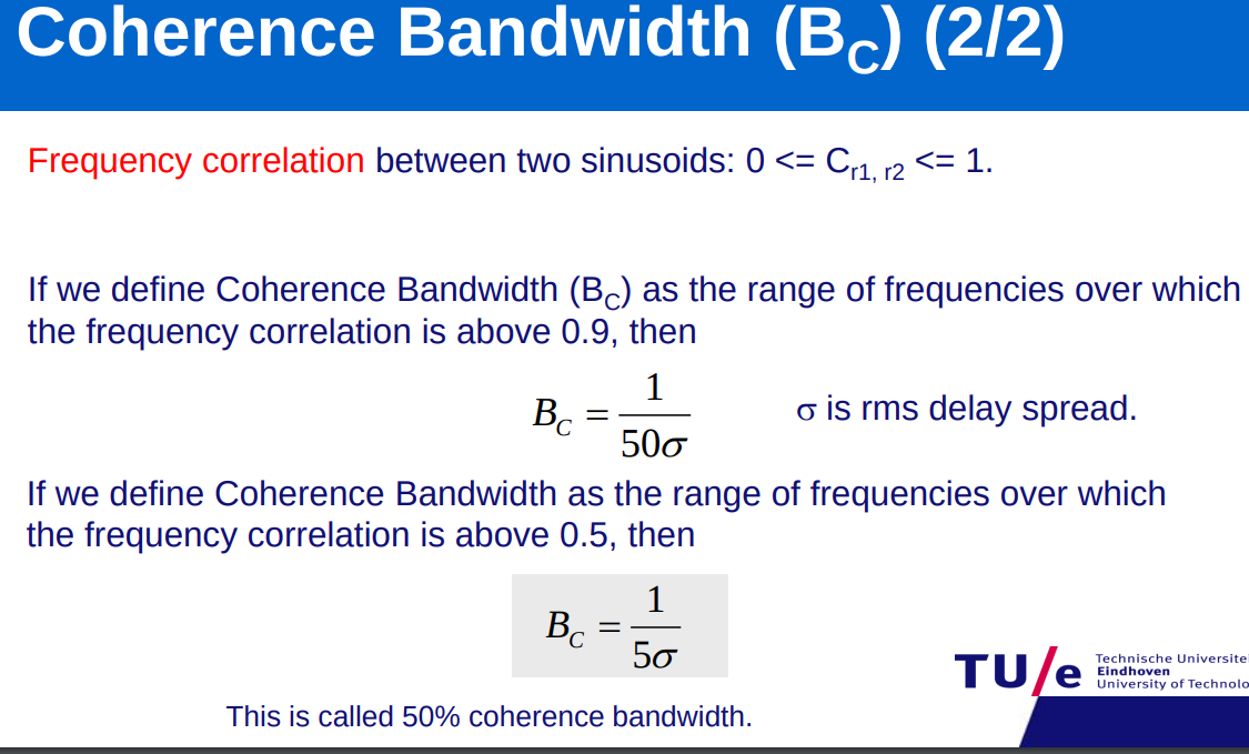
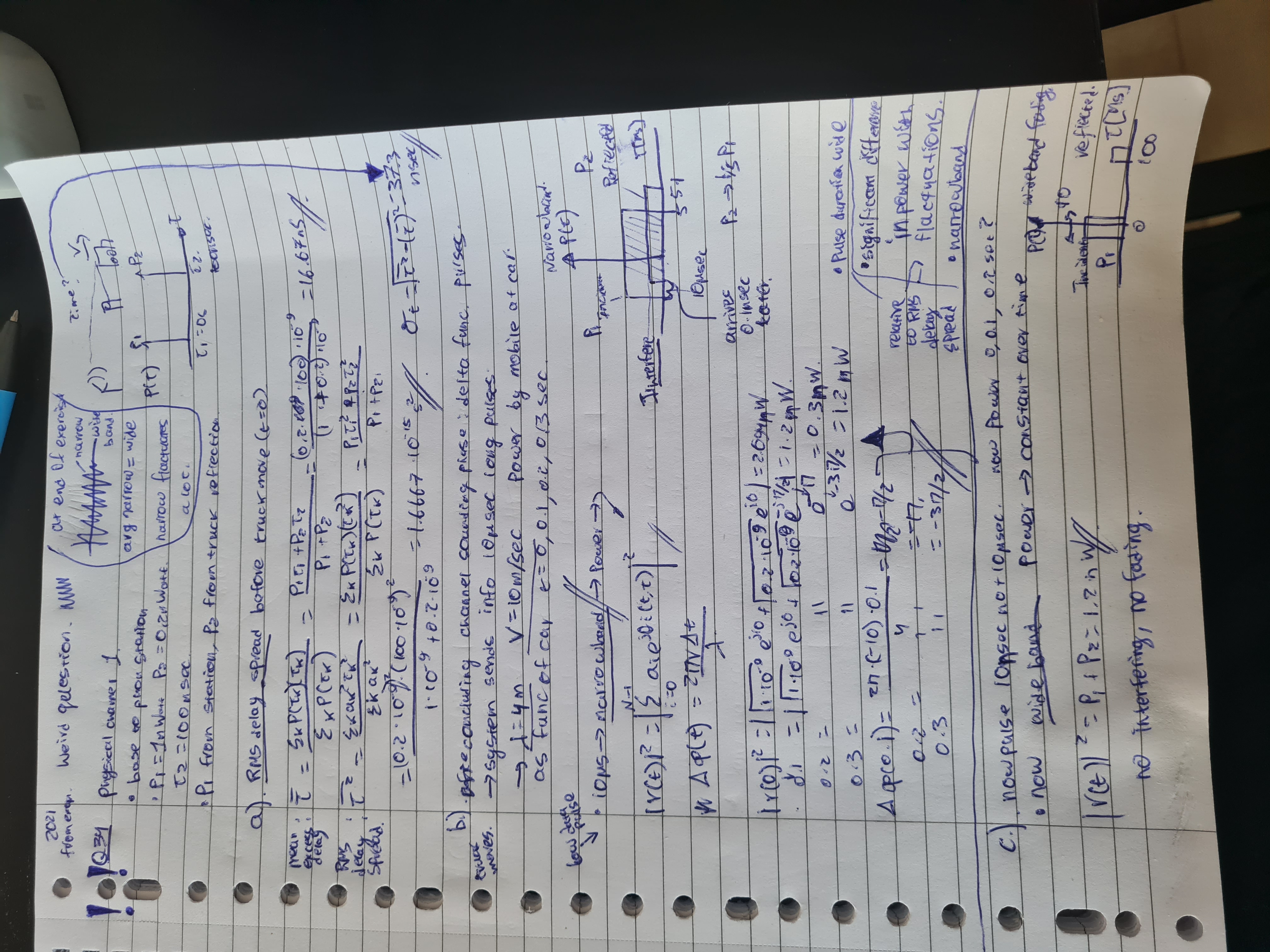
wideband: power constant over time;
Wired Connections.
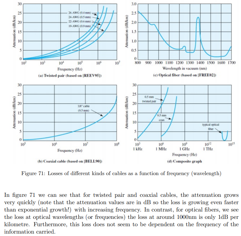
-
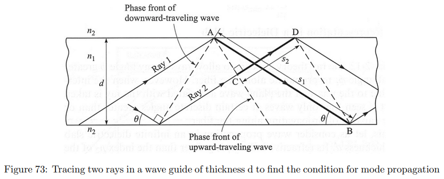
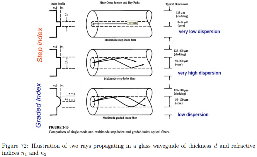
Optical support both step and graded index fibers. remember TIR.
-
Mode propagation condition:
. -
no TIR after
, as angle increase → propagation time increase -
Single Mode vs. Multimode Fiber… What’s the Difference? | NSI-LYNN Electronics, LLC
-
-
where and also basically -
as
increase the 2 pulses may not overlap → so might become indistinguishable (more sensitive to smaller pulses). this is a problem for multi mode fibers. problem for fast modulation. -
where lower spread → faster communication -
modulation speed as inversely proportional to the RMS delay spread than a longer delay spread will entail lower modulation speed.
-
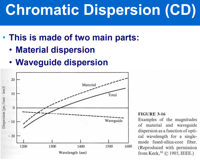
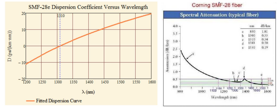
single mode: no model dispersion but has chromatic dispersion
-
modulation bandwidth small [modulation speed slow] → attenuation most critical → choose bigger wavelength
-
modulation bandwidth high[modulation speed high] → dispersion most critical[frequency components arrive at different time problem] → choose lower wavelength