5ESC0 Signals II (DSP Fundamentals)
- Area: Signals and Systems
- Topics: Fourier Transform · Z-Transform · Sampling · Transfer Functions and Frequency Response · Filters · Random Signals and Power Spectral Density
- Related courses: Systems - 5ESB0 · Control Systems - 5ESD0 · Communication 1 - 5ETC0
- Notes by a friend: Fourier Analysis (friend) - 5ESC0 · Laplace Transform (friend) - 5ESC0 · Overview (friend) - 5ESC0 · Prerequisites (friend) - 5ESE0 · Transforms (friend) - 5ESC0 · Z-Transform (friend) - 5ESC0
Pre-knowledge
Introduction_5ESC0 (4).pdf
Geometric series - Wikipedia
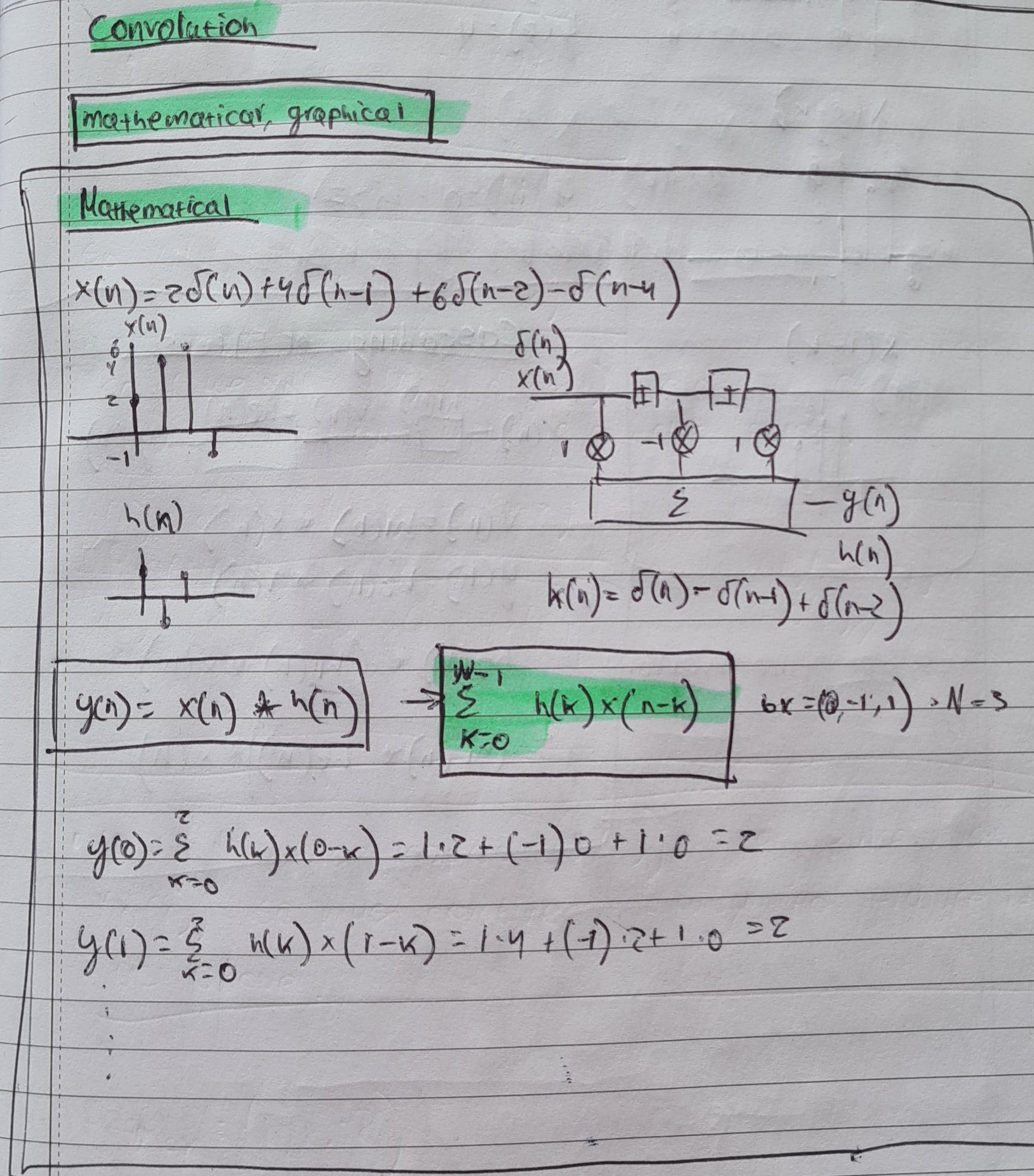
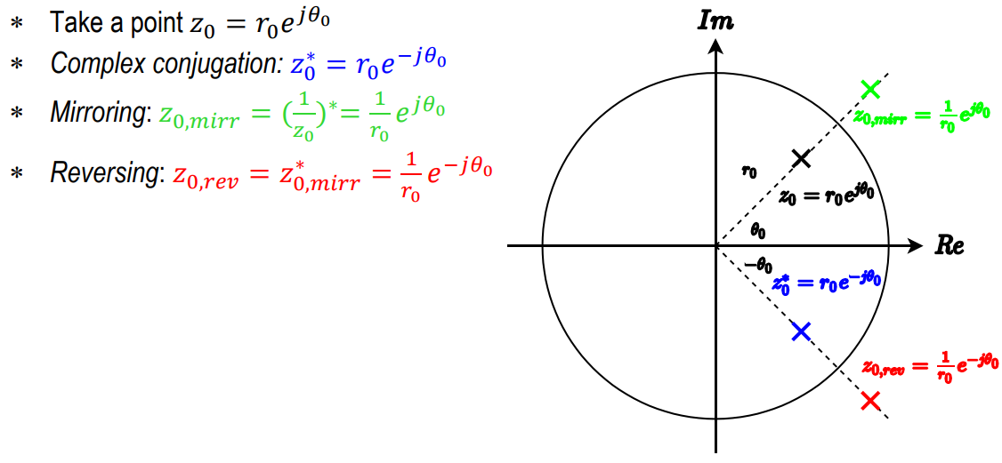
rule of thumbs: zero refers to the function (e.g. polynomial) and root refers to the equation.
3.6: Complex Zeros - Mathematics LibreTexts
Signals and System
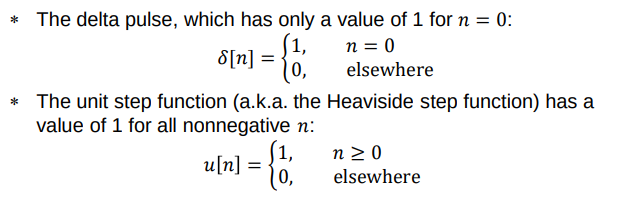
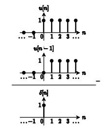
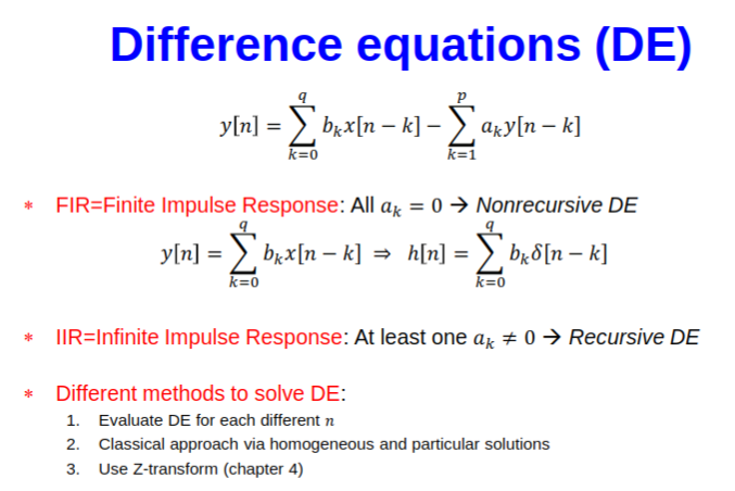
Convolution:
Frequency response:
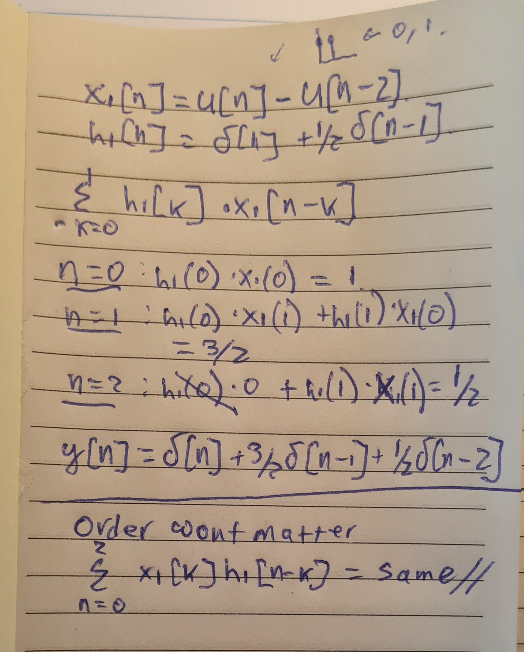
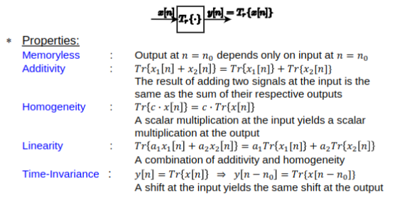
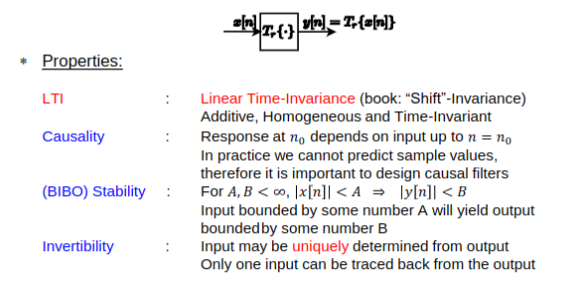
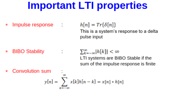
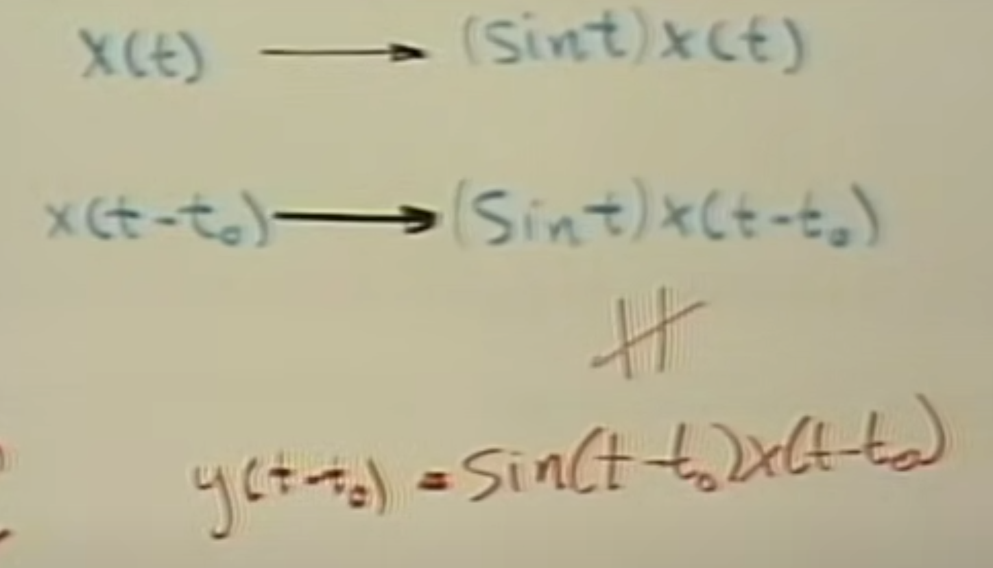
linearity: think of it in root locus plot: if line is continuous no jumps: linear
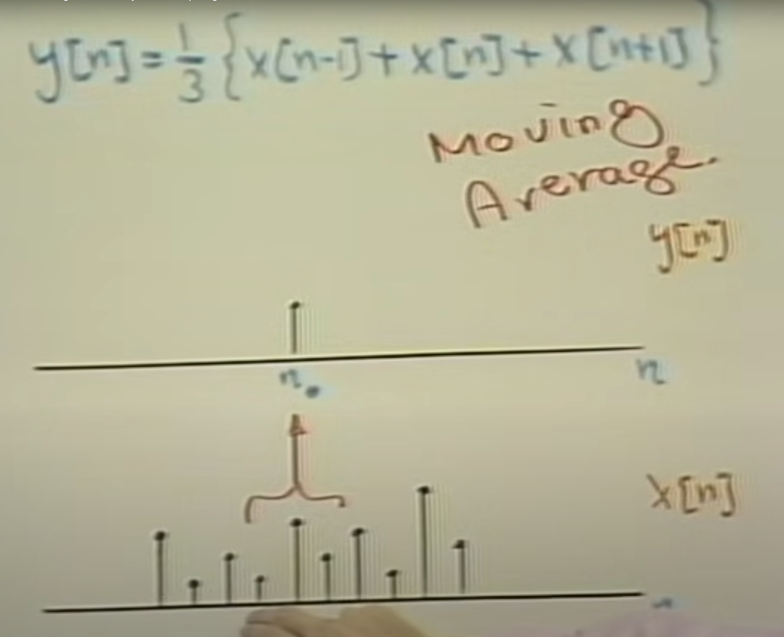
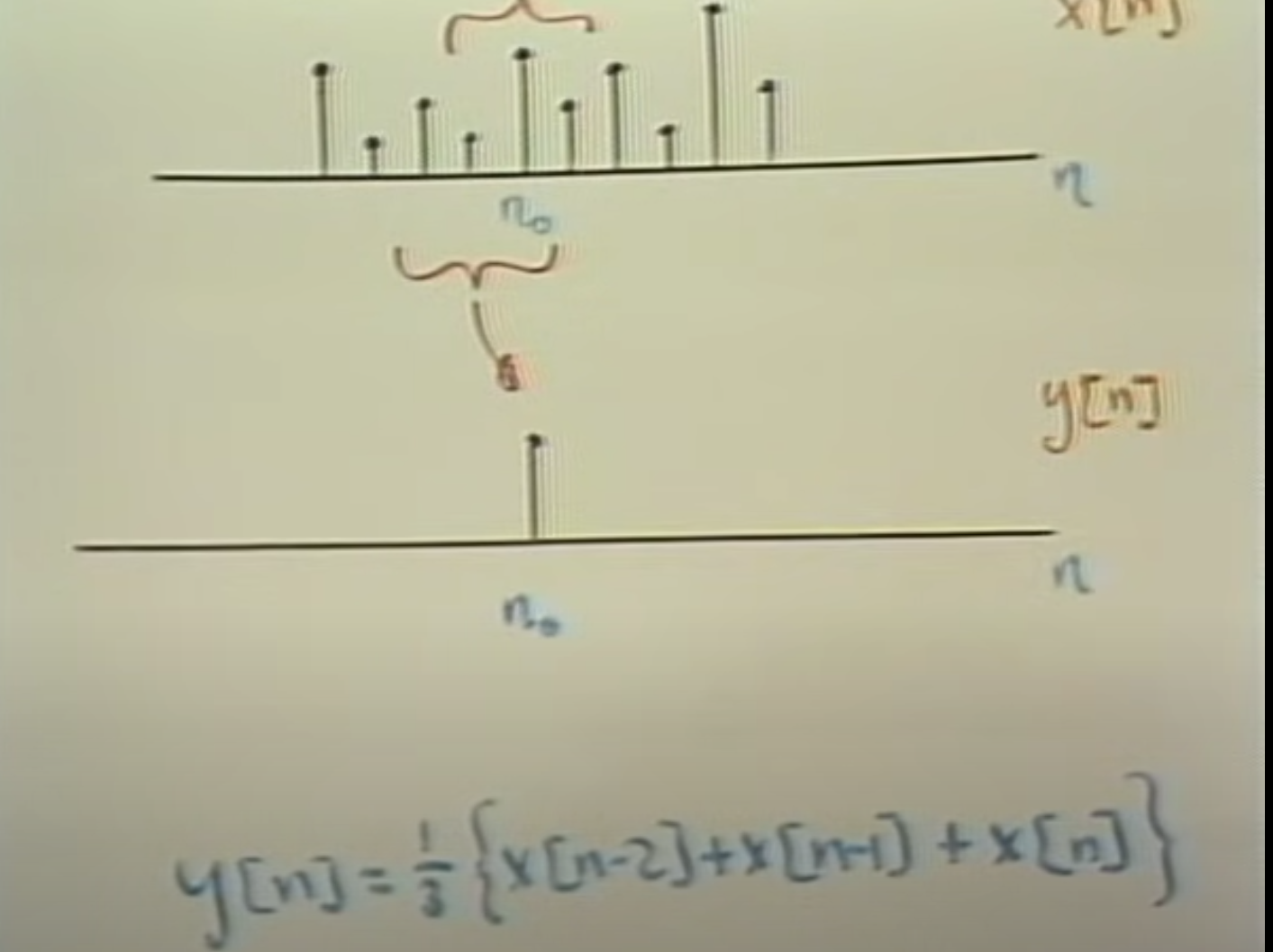
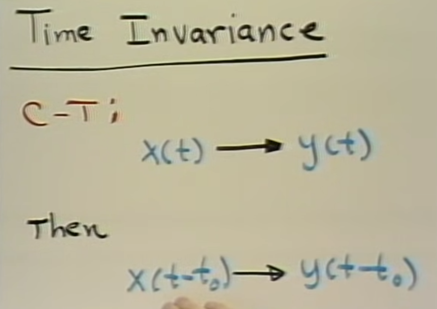
delayed impulses → convolution
complex exponentials → Fourier analysis
Fourier Analysis
Topic: Fourier Transform
Fourier Analysis (friend) - 5ESC0
Fourier Analysis_Peri (1).pdf
Continuous Time Fourier Transform (CTFT)
-
Forward Fourier Transform:
-
Inverse Fourier Transform:
Fourier Series for Periodic Signals
-
Fourier Series Representation:
-
Fourier Series Coefficients:
Fourier Transform of Discrete-Time Signals (FTD)
-
Forward Discrete-Time Fourier Transform (DTFT):
-
Inverse Discrete-Time Fourier Transform (IDTFT):
Common FTD Pairs
-
Delta function in time:
-
Exponential sequence:
Frequency Response of an LTI System
-
Impulse Response and Frequency Response Pair:
-
Convolution in Time Domain:
Sampling
Topic: Sampling
TUe_Signals2_SamplingInterpolation2020.pdf
Convolution Integral
-
Convolution in Time Domain:
-
Convolution Properties:
- Time domain convolution
corresponds to multiplication in frequency domain . - Multiplication in time domain
corresponds to convolution in frequency domain .
- Time domain convolution
Fourier Transform of a Dirac Train (Pulse Train)
-
Dirac Train in Time Domain:
-
Corresponding Fourier Transform in Frequency Domain:
Nyquist Sampling Theorem
To avoid aliasing, the sampling rate
Discrete Fourier Transform (DFT)
-
DFT Expression:
-
Inverse DFT:
Ideal Low Pass Filter
-
Time Domain:
-
Frequency Domain:
Interpolation Formula
For reconstructing a continuous signal
where
The DFT
Topic: Fourier Transform
The DFT_2022_Peri.pdf
Discrete Fourier Transform (DFT)
-
DFT Definition:
-
Inverse DFT (IDFT):
Twiddle Factor
-
Twiddle Factor Definition:
-
Property of Twiddle Factor:
DFT Properties
-
Linearity:
-
Symmetry for Real Sequences:
-
Circular Shift:
- Time Shift:
- Frequency Shift:
- Time Shift:
Circular Convolution
-
Circular Convolution in Time Domain:
-
Circular Convolution Property:
- Convolution in the time domain corresponds to multiplication in the frequency domain:
- Convolution in the time domain corresponds to multiplication in the frequency domain:
Zero Padding
-
Zero Padding:
- Extending a signal
with zeros to increase DFT resolution without changing signal content. - With zero padding, the DFT length
increases, and frequency resolution improves.
- Extending a signal
-
Zero Padding and DFT Resolution:
- For
, frequency bins are apart. - For
, frequency bins are apart.
- For
Practical Applications
- Sampling in DFT Domain:
- Sampling a continuous-time Fourier Transform (CTFT) creates repetitions in the DFT, commonly leading to spectral leakage if not handled with appropriate windowing.
- Windowing:
- Window functions like Hanning window:
- Windowing minimizes edge effects and reduces spectral leakage.
- Window functions like Hanning window:
Z-transform
Topic: Z-Transform
Z-transform.pdf
Z-Transform Definition
-
Z-Transform:
-
Inverse Z-Transform:
Z-Transform Properties
-
Linearity:
-
Time Shift:
-
Scaling in the z-Domain:
-
Convolution:
- Convolution in time domain is multiplication in the z-domain:
- Convolution in time domain is multiplication in the z-domain:
Region of Convergence (ROC)
- For a right-sided sequence (causal):
- For a left-sided sequence:
- For a two-sided sequence, ROC is a ring:
Common Z-Transform Pairs
-
Delta Function:
-
Shifted Delta Function:
-
Exponential Sequence:
-
Cosine Sequence:
Examples of Z-Transforms
-
For
: -
For
:
Z-Transform of Convolution
-
Convolution in the Time Domain:
where ( * ) denotes convolution.
-
Example with Exponential Input:
- For
and : - Then,
.
- For
Inverse Z-Transform (Partial Fraction Expansion)
- Example:
Given:Decompose as: Solve for constants ( A ) and ( B ), and apply inverse Z-transform.
Summary of Important Concepts
- The Z-transform provides a method for analyzing discrete-time signals and systems, particularly useful for characterizing stability and frequency response.
- The ROC determines the stability and applicability of the Z-transform for different signals.
- Common Z-transform pairs and properties allow quick transformations between time and z-domains.
System function
Topic: Transfer Functions and Frequency Response
System_function.pdf
System Function Definition
-
System Function (Z-transform of impulse response):
-
Frequency Response:
LTI System Properties
-
Convolution Property:
- Output
as a convolution of input with impulse response : - In the Z-domain, this corresponds to multiplication:
- Output
-
System Function Expression:
Example System Function
- For a system with difference equation:
- Rearrange to find
:
- Rearrange to find
Poles and Zeros
- Zeros
are the roots of the numerator polynomial. - Poles
are the roots of the denominator polynomial.
Stability and Causality
-
Stability (Bounded Input, Bounded Output - BIBO):
- System is stable if the sum of impulse response values is finite.
- ROC (Region of Convergence) must include the unit circle for stability.
-
Causality:
- A causal system has a right-sided impulse response.
- For a causal system, ROC is outside the outermost pole:
Example: FIR and IIR Filters
-
FIR (Finite Impulse Response) Filter:
- Poles are located at
.
- Poles are located at
-
IIR (Infinite Impulse Response) Filter:
- Poles are within the ROC, but not limited to
.
- Poles are within the ROC, but not limited to
All-Pass System
- Pole-Zero Relationship for All-Pass Filters:
- Zeros are reflected across the unit circle to obtain poles.
- If
, then the mirrored pole is:
Minimum and Maximum Phase
- Minimum-phase system: All zeros are inside or on the unit circle.
- Maximum-phase system: Zeros are outside the unit circle.
Filter structure
Topic: Filters
8 - Filter_structure.pdf
FIR Filter Structure
- FIR Filter:
- Finite Impulse Response (FIR) filter has no feedback loops, meaning it has no poles except at
and . - The FIR filter output can be expressed as:
- Can be implemented using a delay line and multiply-add structure:
- Each delayed signal
) is multiplied by and summed to produce .
- Each delayed signal
- Finite Impulse Response (FIR) filter has no feedback loops, meaning it has no poles except at
Linear Phase Filters
-
Linear Phase Condition:
- A filter has linear phase if its impulse response satisfies:
where ( N ) is the filter order. - The phase shift
is linearly dependent on frequency , ensuring that all frequencies are delayed by the same amount.
- A filter has linear phase if its impulse response satisfies:
-
Impulse Response Symmetry:
- For odd ( N ): symmetry axis coincides with a sample
. - For even ( N ): symmetry axis lies between two samples.
- For odd ( N ): symmetry axis coincides with a sample
Types of Linear Phase FIR Filters
-
Type I: Symmetric impulse response, odd length.
- No restrictions on filter type (can be used as low-pass, high-pass, band-pass, or band-stop).
-
Type II: Symmetric impulse response, even length.
- Has a zero at ( z = -1 ) (cannot be used as a high-pass filter).
-
Type III: Antisymmetric impulse response, odd length.
- Has zeros at
, suitable for band-pass but not low-pass or high-pass.
- Has zeros at
-
Type IV: Antisymmetric impulse response, even length.
- Has a zero at ( z = 1 ), not suitable for low-pass filters.
Frequency Response of Linear Phase FIR Filters
-
For Type I FIR Filter:
- Can be used to design any filter type without restrictions.
-
For Type II FIR Filter:
- Cannot be used to design a high-pass filter.
-
For Type III FIR Filter:
- Cannot be used for low-pass, high-pass, or band-stop due to zeros at
.
- Cannot be used for low-pass, high-pass, or band-stop due to zeros at
-
For Type IV FIR Filter:
- Not suitable for low-pass filters as it has a zero at ( z = 1 ).
Key Properties of FIR Filters
- FIR filters with linear phase have the advantage of maintaining the shape of signals within the passband.
- They are commonly implemented as non-recursive structures with a finite number of taps (coefficients ( h[n] )).
- Filters are stable as they do not rely on feedback, meaning there is no risk of poles moving outside the unit circle.
Summary
- FIR filters can be implemented in various forms (transversal, cascade, etc.) based on application requirements.
- Linear phase is only possible with FIR filters and requires specific symmetry in the impulse response.
- Different types of linear phase FIR filters have distinct applications based on their frequency response characteristics.
Filter design
Topic: Filters
9 - Filter Design.pdf
Ideal Filter Examples
-
Ideal Low-Pass Filter:
where
is the cutoff frequency. -
Ideal High-Pass Filter:
-
Ideal Band-Pass Filter:
-
Ideal Band-Stop Filter:
Filter Design Specifications
- Passband Ripple
: Allows a specified maximum ripple in the passband. - Stopband Attenuation
: Defines the minimum attenuation level in the stopband, often given in dB.
FIR Filter Design Process (Windowing Method)
-
Filter Length:
- The filter length ( N ) is chosen to control the filter’s main lobe width and transition width.
- As ( N ) increases, the main lobe narrows, decreasing the transition width.
-
Window Types and Characteristics:
- Rectangular Window:
- Main lobe width
- Peak sidelobe level: -13 dB.
- Main lobe width
- Hanning Window:
- Main lobe width
- Peak sidelobe level: -31 dB.
- Main lobe width
- Hamming Window:
- Main lobe width
- Peak sidelobe level: -41 dB.
- Main lobe width
- Blackman Window:
- Main lobe width
- Peak sidelobe level: -57 dB.
- Main lobe width
- Rectangular Window:
-
Filter Coefficients:
- Impulse response ( h[n] ) for a low-pass filter:
- Impulse response ( h[n] ) for a low-pass filter:
FIR Filter Design Using Frequency Sampling
- Desired frequency response
is sampled at uniformly spaced frequencies. - FIR filter coefficients ( h[n] ) are obtained via Inverse Discrete Fourier Transform (IDFT).
Equiripple Linear Phase FIR Filter
- Allows ripple to be uniformly distributed across the passband and stopband, producing a smaller peak ripple than non-equiripple methods.
Stochastic signals
Topic: Random Signals and Power Spectral Density
Stochastic Signals.pdf
Stochastic Process Basics
-
Ensemble Average (Expected Value):
where
is the probability of occurrence of the random variable . -
Mean Estimate:
Second-Order Statistics
-
Mean:
-
Variance:
-
Autocorrelation:
-
Autocovariance:
-
Cross-Correlation (between two processes
and ): -
Cross-Covariance:
Wide Sense Stationarity (WSS)
- A process
is WSS if: - Mean
is constant over time. - Autocorrelation
depends only on the lag , not on .
- Mean
Ergodicity
-
Time-Averaged Mean for Ergodic Signals:
-
Time-Averaged Variance:
-
Autocorrelation for Ergodic Signals:
Power Spectral Density (PSD)
- Wiener-Khinchin Relation:
- The average power:
Example PSD Calculation
- For
with :