5EWA0 Electromechanics
- Area: Power and Energy
- Topics: Magnetic Circuits and Transformers · Electric Machines · Three-Phase Power
- Related courses: Electric Power Systems - 5EWB0 · Electromagnetics I - 5EPA0
Content
2 Weekly Instructions, 4 Homework, Labs
Cheat Sheet 4 Pages
Magnetic equivalent circuits
- apply all governing laws and rules which describe the relations among electrical, magnetic and mechanical quantities.
- use engineering language related to electrical machine and explain and define the related quantities (such as MMF, EMF, flux linkage, apparent and incremental inductance, leakage, fringing, stacking factor, saturation, BH-curve, remanence, coercivity, and
diagram). - analyze magnetic circuits with coils and permanent magnets as source of the MMF.
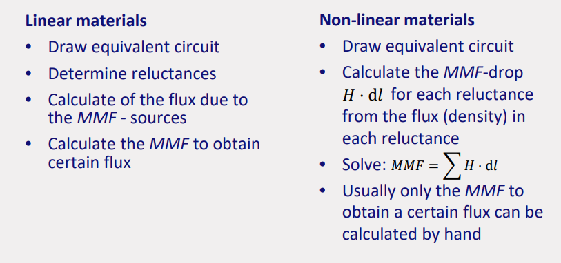
- analyze magnetic circuits with and without non-linear magnetic materials.
- use the electrical quantity inductance to link magnetic field variables to an electric circuit.
- calculate the electromagnetic force using magnetic energy and magnetic co-energy.
DC machines
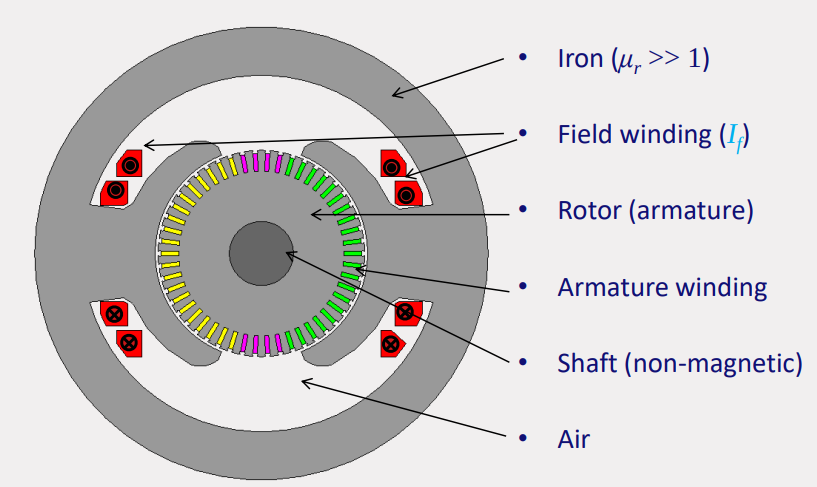
- describe the different parts of a DC machine and indicate them in a cross-section.
- derive an expression for the EMF in the armature as function of the construction of a DC machine.
- derive an expression for the electromagnetic torque as function of the construction of a DC machine.
- classify a DC machine depending on the connection of the field winding (separately excited, shunt excited and series excited machines).
- derive the equivalent circuits of the different types of DC machines and determine expressions for the electromagnetic torque and speed.
- analyse the DC machine with the equivalent circuit and the power flow.
- analyse and explain different speed control methods for DC machines.
Synchronous machines
- describe the different parts of a synchronous machine and indicate them in a cross-section.
- classify synchronous machines based on the physical construction of the stator and rotor.
- derive an equation for the rotor excitation field.
- derive an equation for the induced voltage in the stator due to the rotor excitation field.
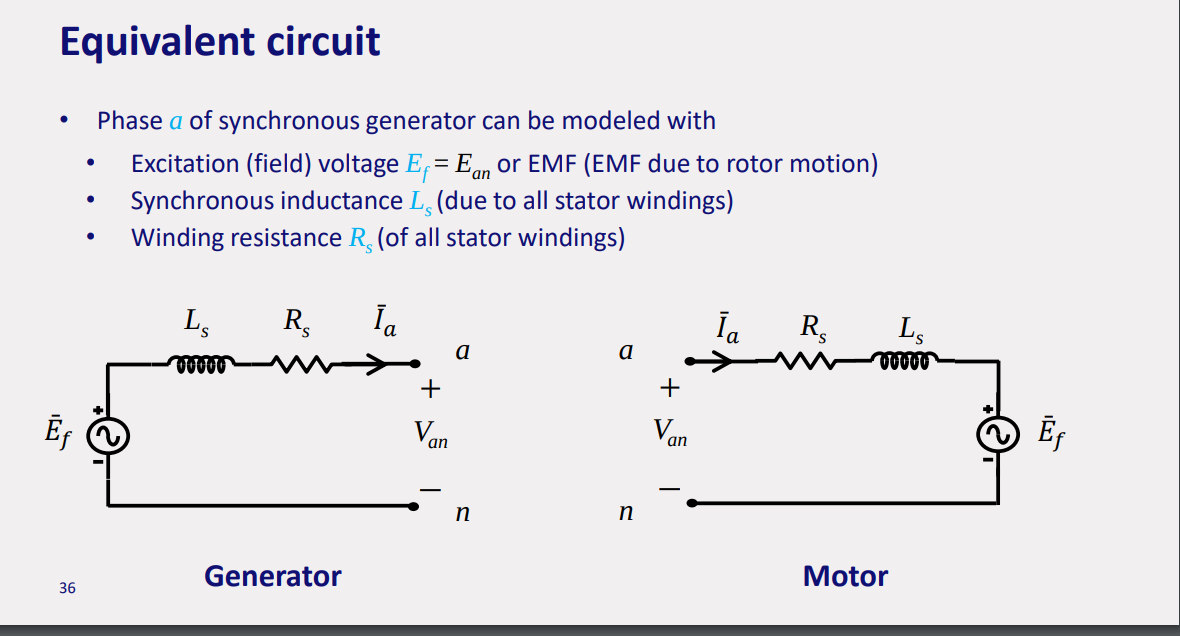
- derive the per-phase equivalent scheme of a three-phase synchronous machine and determine expressions for the electromagnetic torque and speed (cylindrical rotor only).
- draw and analyze the phasor diagram of a three-phase synchronous machine.
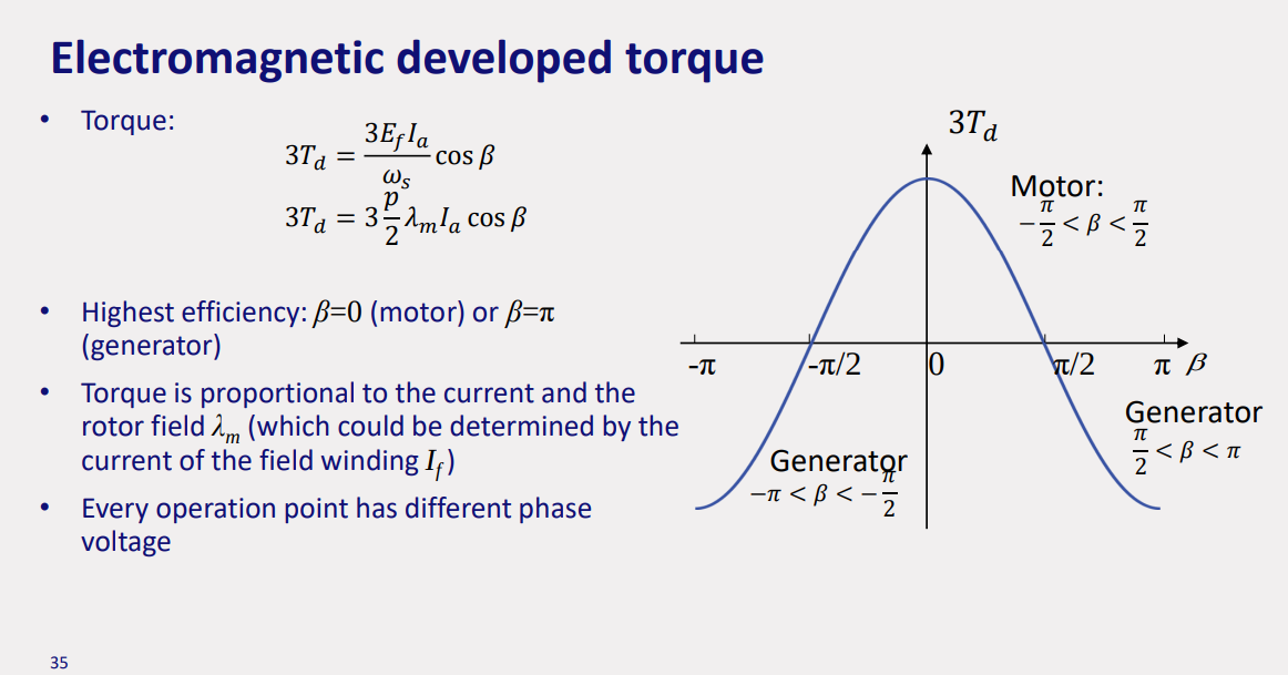
- explain and evaluate the torque-speed characteristic in a synchronous machine.
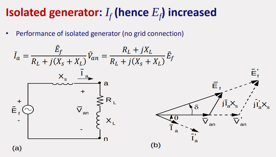
- analyze the behaviour of an isolated synchronous machine.
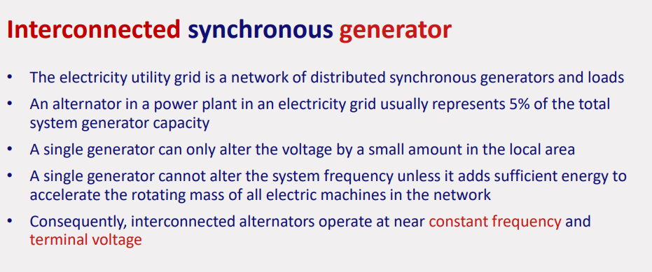
- analyze the behaviour of interconnected/grid-connected synchronous machines.
- analyze the behaviour of a synchronous motor.
Induction machines
- describe the different parts of an induction machine and indicate them in a cross-section.
- classify an induction machine based on the physical construction of the stator and rotor.
- explain methods to reduce harmonics in the stator field of an induction machine.
- derive the equations of the rotating stator field and its speed.
- calculate the speeds of the fields inside an induction machine based on the quantity slip.
- derive the per-phase equivalent scheme of a three-phase induction motor and determine expressions for the electromagnetic torque and speed.
- derive the parameters of the per-phase equivalent scheme of a three-phase induction machine based on a no-load and a blocked rotor test.
- analyze the active power flow in an induction machine.
- explain and evaluate the torque-speed characteristic in an induction machine and its special characteristics.
- compare and describe speed control methods for induction machines.
Basics
AC MACHINE: https://www.youtube.com/watch?v=lV8iPKY-3ms&t=35s
there is Induction Machines and Permanent Magnet Machines
DC MACHINE: https://www.youtube.com/watch?v=1AaUK6pT_cE
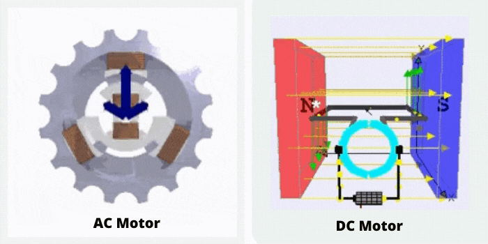
https://hermitageautomation.com/difference-between-ac-and-dc-motor/
- Mechanical Speed (nₘ): Measured in revolutions per second (rev/s), it represents the rotational speed of a mechanical component in an electromechanical system.
- Field Voltage of the DC Machine (Vf): Expressed in volts (V), it refers to the voltage applied to the field winding of a DC machine, which generates the magnetic field necessary for its operation.
- Field Current of the DC Machine (Iₑ): Measured in amperes (A), it denotes the electric current flowing through the field winding of a DC machine.
- Armature Voltage of the DC Machine (Vₐ): In volts (V), this is the voltage across the armature winding of a DC machine, influencing its speed and torque.
- Armature Current of the DC Machine (Iₐ): Measured in amperes (A), it represents the current flowing through the armature winding of a DC machine, impacting its torque production.
- RMS Phase Voltage of the ACM (Vₚₕ): Root Mean Square (RMS) phase voltage in volts (V) of an Alternating Current Machine (ACM), indicating the effective voltage in one phase of the machine.
- RMS Phase Current of the ACM (Iₚₕ): Root Mean Square (RMS) phase current in amperes (A) of an Alternating Current Machine (ACM), showing the effective current in one phase of the machine.
- Power Factor of the ACM (PF): A dimensionless number (represented by -), it is the ratio of real power flowing to the load to the apparent power in the circuit in an Alternating Current Machine (ACM), indicating efficiency.
-
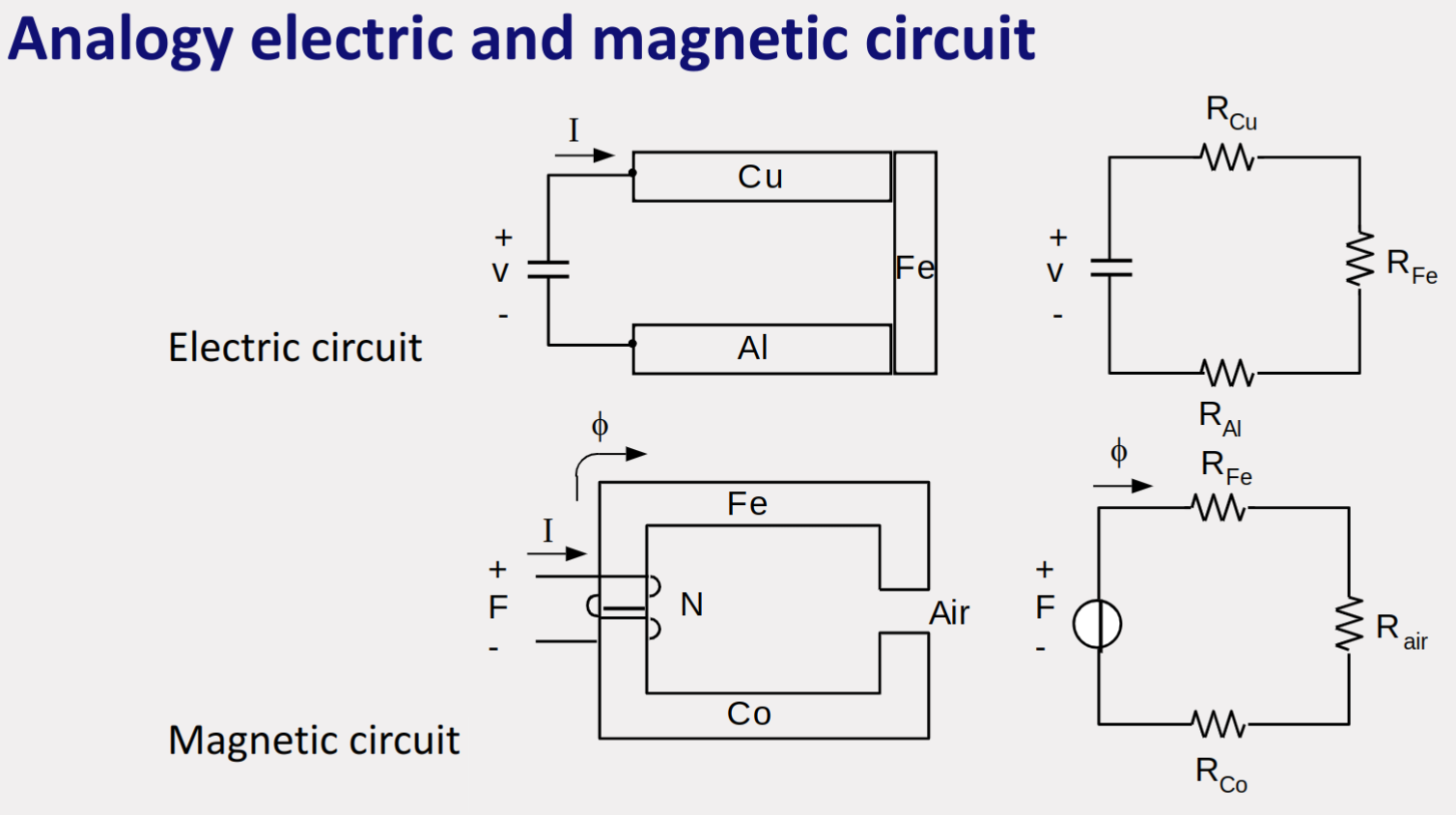
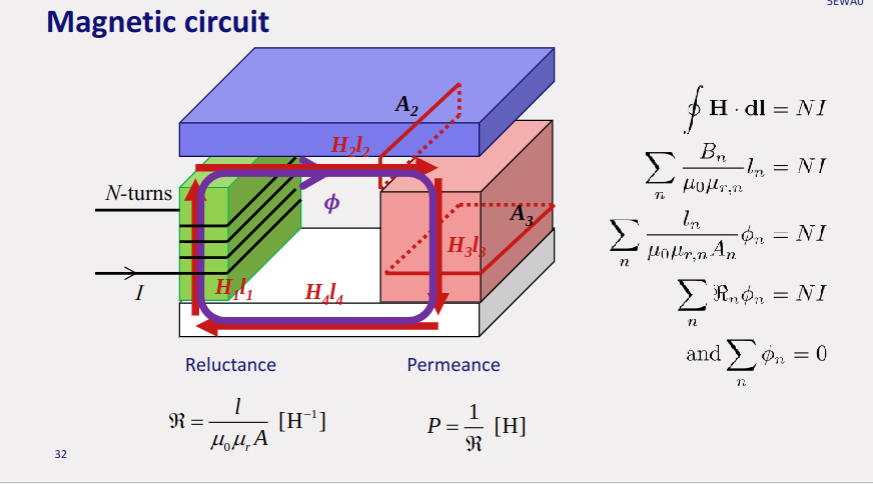
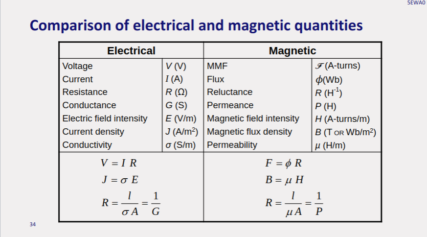
MMF (Magnetomotive Force): MMF is analogous to voltage in electrical circuits but applies to magnetic circuits. It is the driving force that sets up magnetic flux in a magnetic circuit. It’s calculated as the product of the current and the number of turns in the coil (MMF = NI, where N is the number of turns and I is the current).
-
EMF (Electromotive Force): EMF is the electrical action produced by a non-electrical source. In electrical machines, it refers to the voltage induced in a coil by the change in magnetic flux. Faraday’s law quantifies this as EMF = -dΦ/dt, where Φ is the magnetic flux.
-
Flux Linkage: Flux linkage is a measure of how much magnetic flux is ‘intercepted’ by a coil. It is the product of the number of turns in the coil and the magnetic flux through the coil (Ψ = NΦ). This quantity is crucial in understanding how effectively a coil couples with the magnetic field.
-
Apparent and Incremental Inductance: Apparent inductance is the overall inductance of a coil in a magnetic circuit, considering the core material’s non-linearity and saturation. Incremental inductance is the derivative of the flux linkage with respect to the current (dΨ/dI), representing how the inductance changes for small changes in current.
-
Leakage: In electrical machines, leakage refers to the portion of the magnetic field that does not follow the intended path in the magnetic circuit, often due to air gaps or imperfect core materials. This phenomenon reduces the efficiency of magnetic coupling in devices like transformers and motors.
-
Fringing: Fringing occurs at air gaps in magnetic circuits where the magnetic field lines spread out. This effect can lead to a non-uniform distribution of the magnetic field and is particularly significant in devices with narrow air gaps.
-
Stacking Factor: This refers to the ratio of the actual volume of the steel (or core material) to the gross volume of the core. It accounts for the fact that in real-world cores, there are non-magnetic gaps (like insulation and air spaces) between the sheets or laminations of the core material.
-
Saturation: Saturation in a magnetic material refers to the state where an increase in magnetomotive force (MMF) produces little or no increase in magnetic flux. This occurs because the magnetic domains in the material are nearly fully aligned and cannot contribute further to the total magnetization.
-
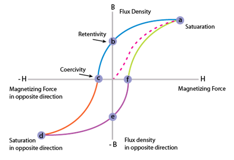
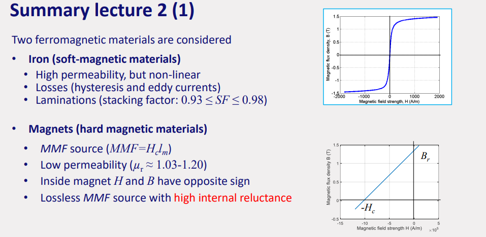
B-H Curve: The B-H curve (or magnetization curve) plots the magnetic flux density (B) against the magnetic field strength (H) for a material. This curve shows the relationship between B and H and is crucial for understanding the magnetic properties of materials, including their behavior under different levels of magnetization and saturation.
-
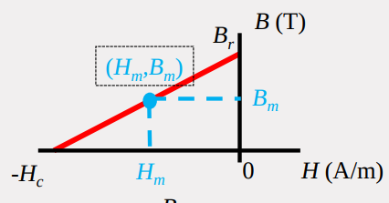
Remanence: Remanence (or residual magnetism) is the magnetization that remains in a magnetic material after an external magnetizing field is removed. It is a key property in permanent magnets, where a high remanence is desirable.
-
Coercivity: Coercivity is the measure of the resistance of a ferromagnetic material to becoming demagnetized. It is the intensity of the applied magnetic field required to reduce the magnetization of that material to zero after the magnetization of the sample has been driven to saturation.
-
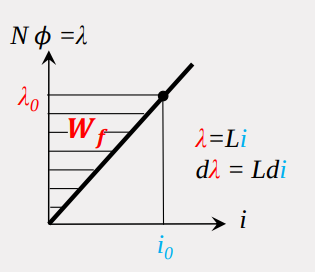
Lambda-i Diagram: The lambda-i (Ψ-I) diagram is a graph representing the flux linkage (Ψ) versus the current (I) in an electrical machine. This diagram is useful in analyzing the magnetic characteristics of the machine, including saturation and non-linear inductance effects.
Magnetic Circuits & Energy Conversion
Topic: Magnetic Circuits and Transformers
magnetic circuits with air gap: https://www.youtube.com/watch?v=T99_3l0UqB8
b-h curve: https://www.youtube.com/watch?v=sEGLcpmIIBY
Definitions
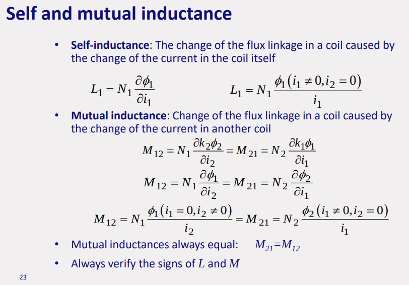
Inductance: Link between- Magnetic flux linkage & - Current ⇒
There is also ReluctanceMagnetic field strength or field intensity (H) is the amount of magnetising force. Magnetic flux density (B) is the amount of magnetic force induced on the given body due to the magnetising force H.
Coercivity, also called the magnetic coercivity, coercive field or coercive force, is a measure of the ability of a ferromagnetic material to withstand an external magnetic field without becoming demagnetized.
Inductance is the ratio of the flux linkage of the coil, and the current which flows in that coil. Flux linkage (Ψ) is the product of the number of turns and flux which penetrates the coil:
Formulas
Magneto-motive force (MMF):
Flux:or
Permanent Magnet:or
C-shape with electromagnet:
Permeance of Air Gap(no fringing):
Coil current:
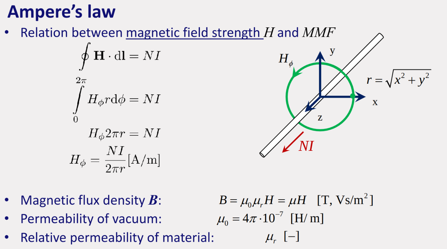
Flux: amount of fields passing through surface,
closed loop
Lamination:
Fringing: Magnetic field doesn’t cross air-gap
Leakage: Considered when magnet saturated as it increases then:
Paramagnetism refers to materials like aluminum or platinum which become magnetized in a magnetic field but their magnetism disappears when the field is removed. Ferromagnetism refers to materials (such as iron and nickel) that can retain their magnetic properties when the magnetic field is removed.
Hysteresis loss & Eddy current loss: https://www.motioncontroltips.com/hysteresis-loss/
Hysteresis: magnetization removed, doesnt return to original state, low frequency
Eddy current: switching magnetic, induce voltage/current:, high frequency, lamination helps
Magnetic Circuit Analysis
MMF:
Air gap are added for increasing the reluctance → lowers the flux intensity → which lowers saturation (lower slope) meaning the can operate with higher MMF. Since reluctance is how MMF affects magnetic flux.
Permanent Magnet Modelling
as
Inductance
linear case:eg:
so so non-linear: (apparent)
, (incremental) due to coupling coefficient (apparent inductance):
, eg: → Causes mutual inductance mutual inductance:
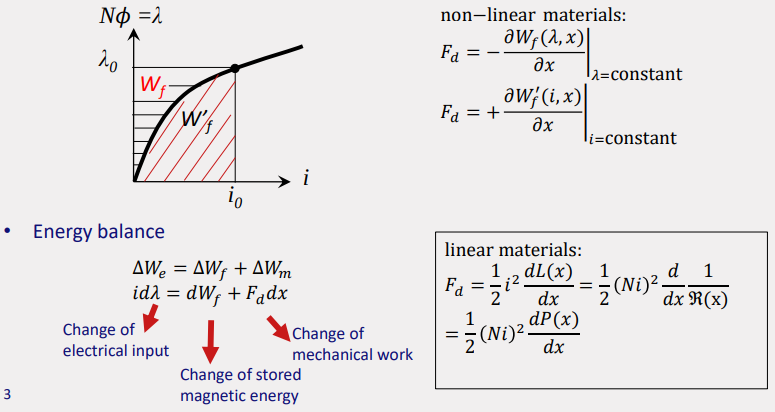
Energy
Stored magnetic energy:
(no displacement, no motion):(no displacement):
and so: linear case
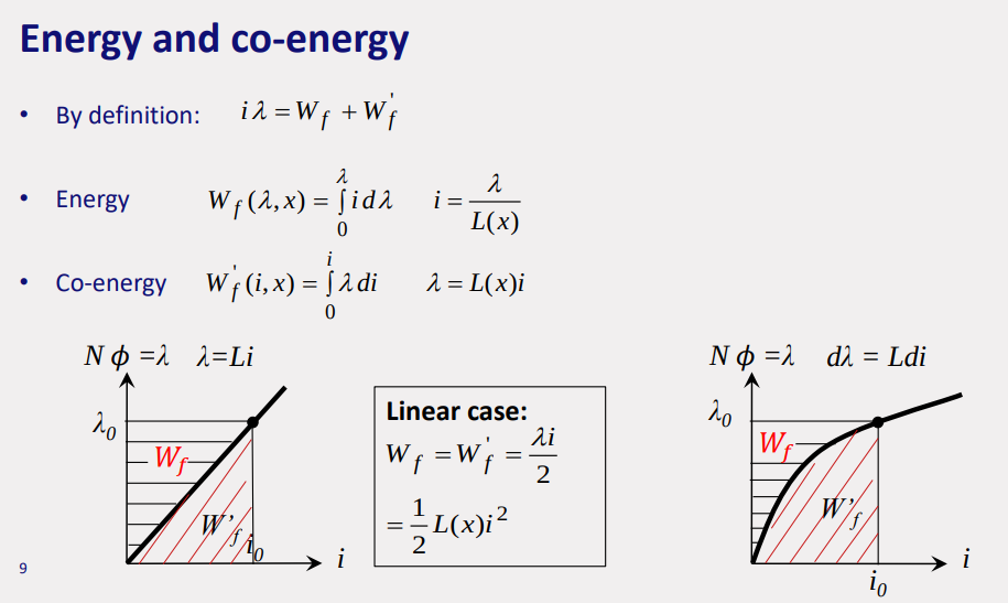
, m-mechanical, f-magnetic - e-(ohmic losses in coil), m-(friction), f-(hysteresis & eddy current losses)
Work
linear system:
rotary system:
permanent magnet:
Multiple coils would mean addition of mutual inductance
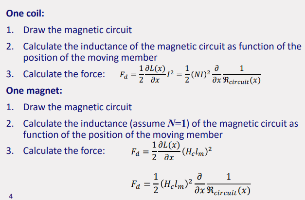
All inductances as function of position of moving member
System with multiple coils:
1st: reluctance force by coil 1
2nd: reluctance force by coil 2
3rd: interaction between the coilsSystem with permanent magnet and coil:
1st: Reluctance torque due to coil
2nd: Reluctance torque due to magnets
3rd: Interaction between magnet & coil ⇒
: is the total permeance of magnetic circuit seen from permanent magnet
Faraday Law
- Faraday Law:
- Lenz Law: The voltage induced in a coil by a changing flux will be of such a polarity that, if a current could flow as a result of that induced voltage, the flux established by that current would oppose the causing or original flux change.
- Transformer emf devices are based on the generation of emf in a stationary circuit, in which the emf is generated by a time-varying magnetic field linking the circuit. Motional emf devices are based on the generation of emf due to a moving conductor within a stationary magnetic field.
DC Machine Principle
The armature winding combines with the magnetic field formed in the air gap. The function of an armature is multi-purposed. The main role is to conduct current over the field, thus generating shaft torque within an active machine. The secondary purpose of an armature is to produce Electromotive Force (EMF).
so: flux in coil
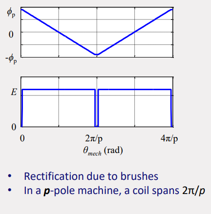
torque:and due to motion of coil emf induced:
Lenz law counteracts change in flux:
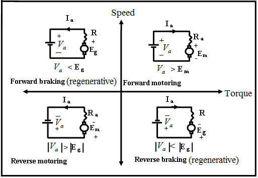
summary:emf
speed
torquecurrent
regenerative: Generator
motoring: motor
DC Machines
Topic: Electric Machines
https://www.youtube.com/watch?v=LAtPHANEfQo
EMF and Torque in Armature
number of conductors coils
number of parallel coils
number of poles EMF constant
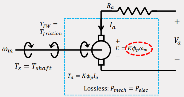
induced armature voltage (emf):
Torque constant
torque:
where:
Torque or emf const
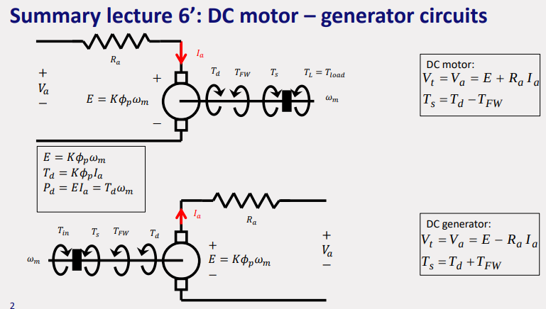
Power Conversion:
DC Machine Operation
generator:
in opposite direction of shaft rotation as its resisting motion and generates power
motor: direction of rotationproviding driving force.
Field Winding
https://www.youtube.com/watch?v=xi0jaPAl2II
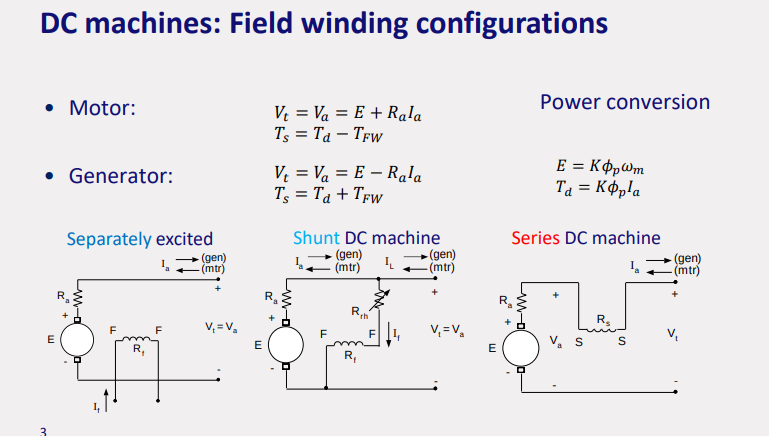
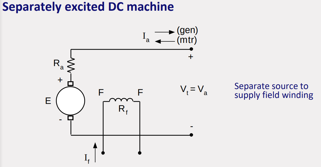
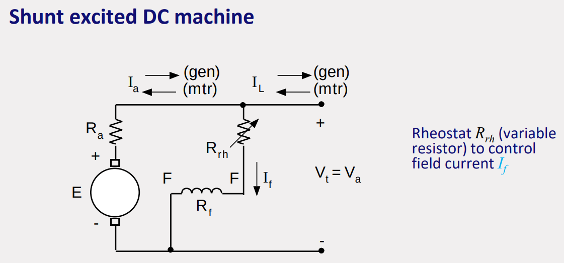
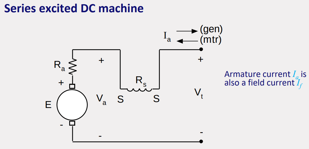
Field winding (producing) connections:
- Separately: excited
- Shunt : parallel to armature
- Series: in series with armature
- Permanent magnet: fixed value
Connection determines:
Torque speed (
) - characteristic (motor operation) Voltage current (
) - characteristic (generator operation)
reluctance network field winding:
Open-circuit characteristic:
due to hysteresis
, , , for shunt
is calculated with KCL, while for separate calculated The field winding of a series DC motor has fewer turns with a higher cross-section area. For constant terminal voltage, a shunt excited DC motor has a linear dependency between shaft torque and shaft speed. A series excited DC motor has a nonlinear dependency between shaft torque and shaft speed.
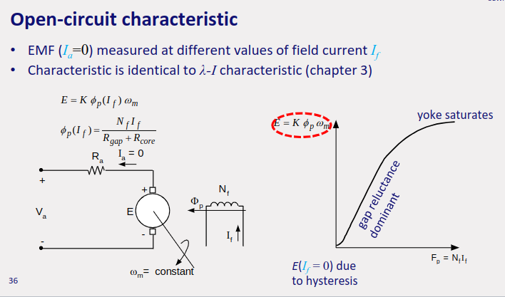
Open circuit characteristic:
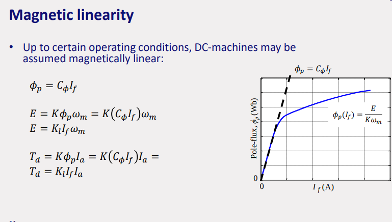
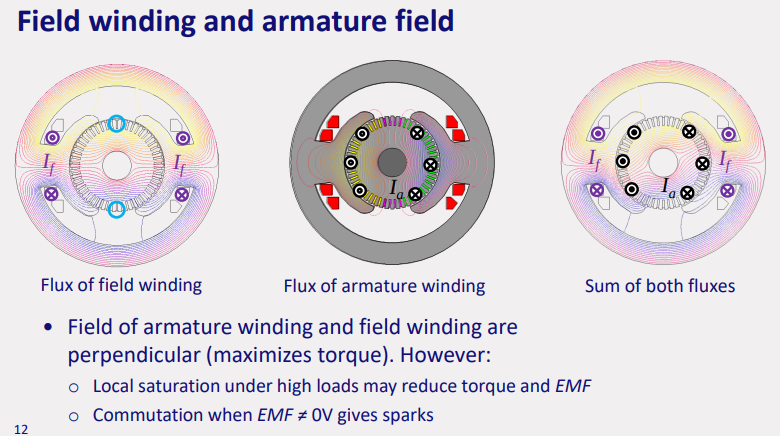
we have multiple fields on the motor that effect the torque. field and armature.
armature reaction: when armature is neglected
speed regulation for shunt dc motor:
- When it is operated as a motor, the machine will have a higher shaft speed. When it is operated as a generator, it will have a lower terminal voltage.
Power Flow
generator:
generator:
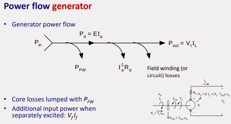
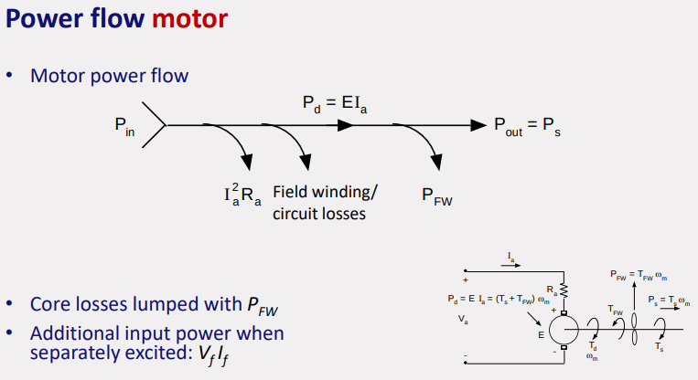
Additional input power when separately excited:
https://www.tutorialspoint.com/types-of-dc-generator-separately-excited-and-self-excited-dc-generators
DC Generator Characteristics: Stable voltage source: Separately and shunt excited • Reduced voltage for higher currents due to : • Internal series resistance: Ra • Internal parallel resistance Rf (shunt only).
Separately excited DC Generator: • Nearly constant output voltage at constant shaft speed • Additional DC source for field supply
Shunt excited DC Generator: • No additional source for field necessary • Without voltage regulator, field current decreases directly with terminal voltage due to load current increase (at constant shaft speed), • Iterative process needed to determine EMF with varying load
no load (
field resistance line:
Series DC Generator: • Independent source for field excitation is not required. • Terminal voltage changes significantly with a change in load current; • Unacceptable to be used as a DC power supply.
DC Motor Characteristics: • At constant terminal voltage: Shunt DC and separately excited motors have identical performance • Shunt and separately excited motors have small change of speed when load is varied (constant voltage)
Shunt excited DC Motor: • Shunt motor has the most constant speed of all DC motor configurations without field current control.
Series excited DC Motor: • Field current is equal to armature current • High torque at low speed o Traction o Automotive cranking (starter) motors.
linearization of
motor starting:
speed control through: field, armature resistance, armature voltage control
field control for shunt DC motor:
field control for series DC motor:
armature resistance control for shunt motor: external resistors added to armature circuit so
armature voltage control for seperatly DC motor: variable high power DC voltage source feeds armature, so
Synchronous Machines
Topic: Electric Machines
https://www.youtube.com/watch?v=Vk2jDXxZIhs
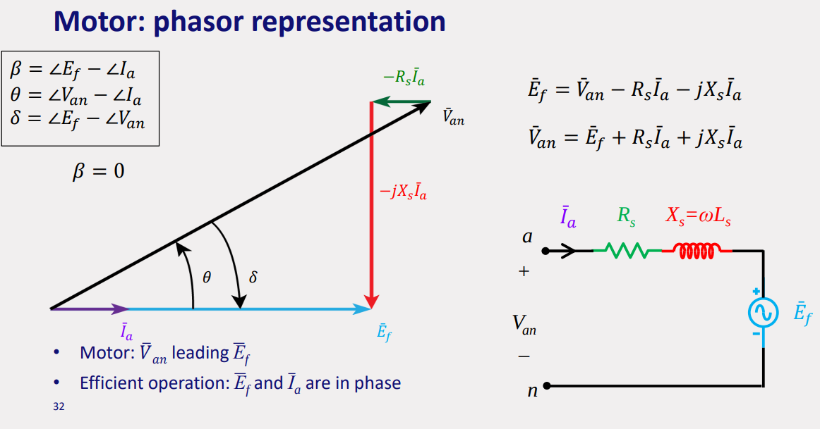
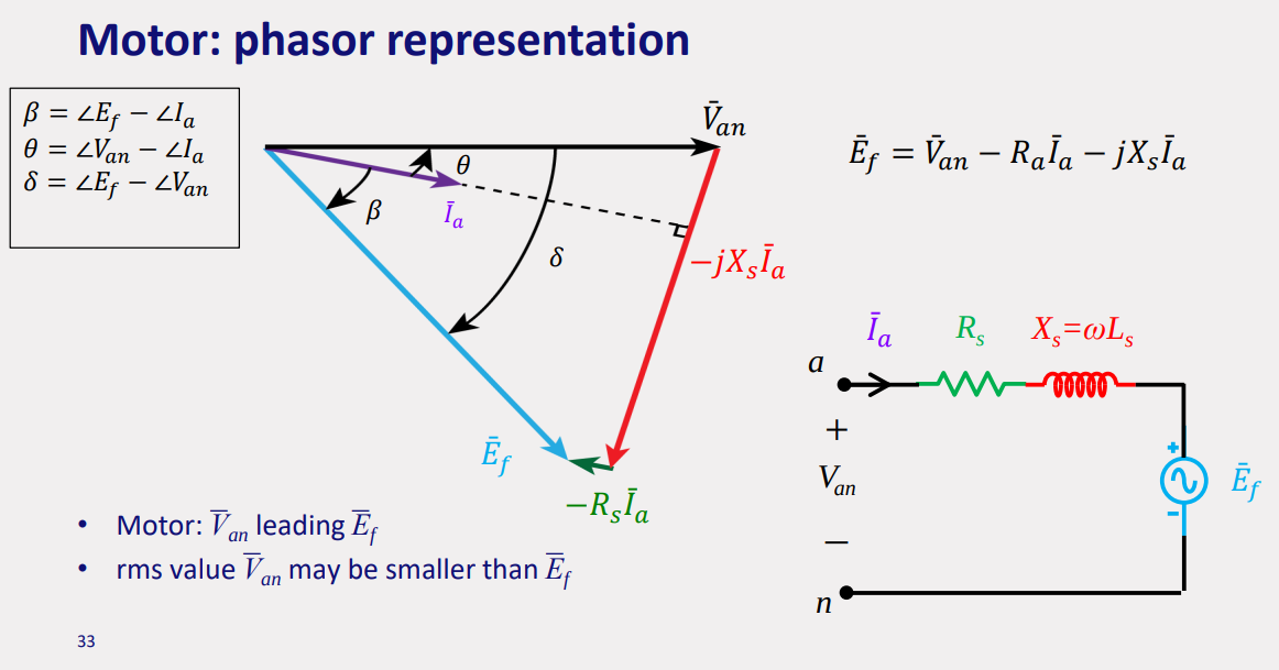
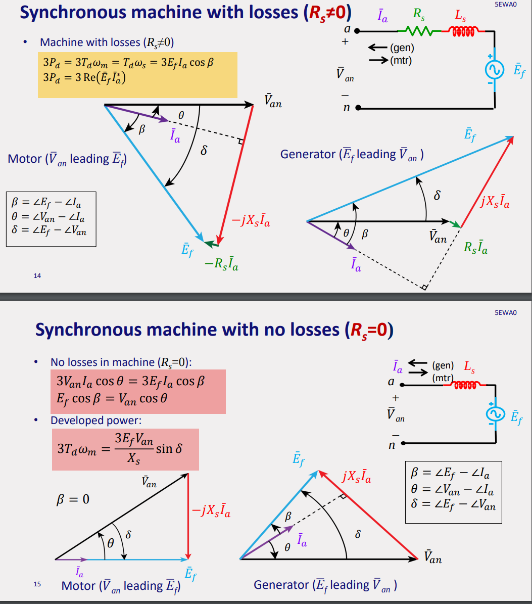
always: do equivalent circuit, phasor diagram, equations, simulations
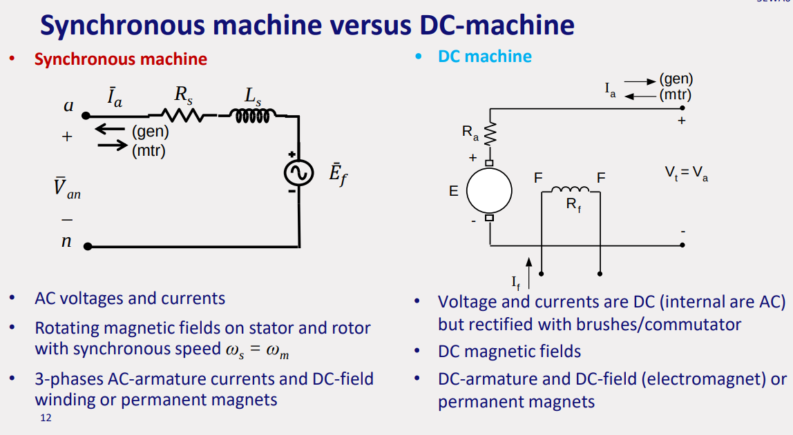
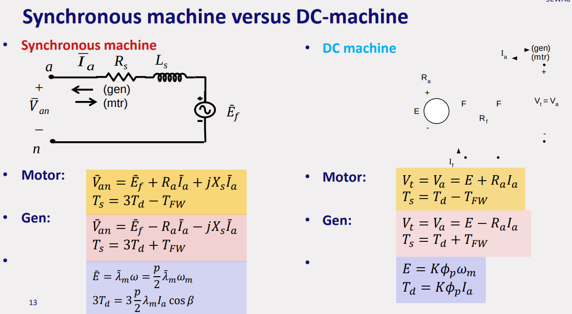
- In DC the coil rotated in the field, in synchronous the field rotates while the coil is stationary.
- nameplate = line voltage → terminal voltage
- excitation voltage = phase voltage
- circuit model requires phase voltage
- only work with (wye) connection
- always transfer line voltages to phase voltages
- resistive load: in phase V, I so pf=1, inductive: I lagging, capacitive: I leading
phase resistance synchronous reactance
synchronous, mechanical, electric frequency
electric frequency:
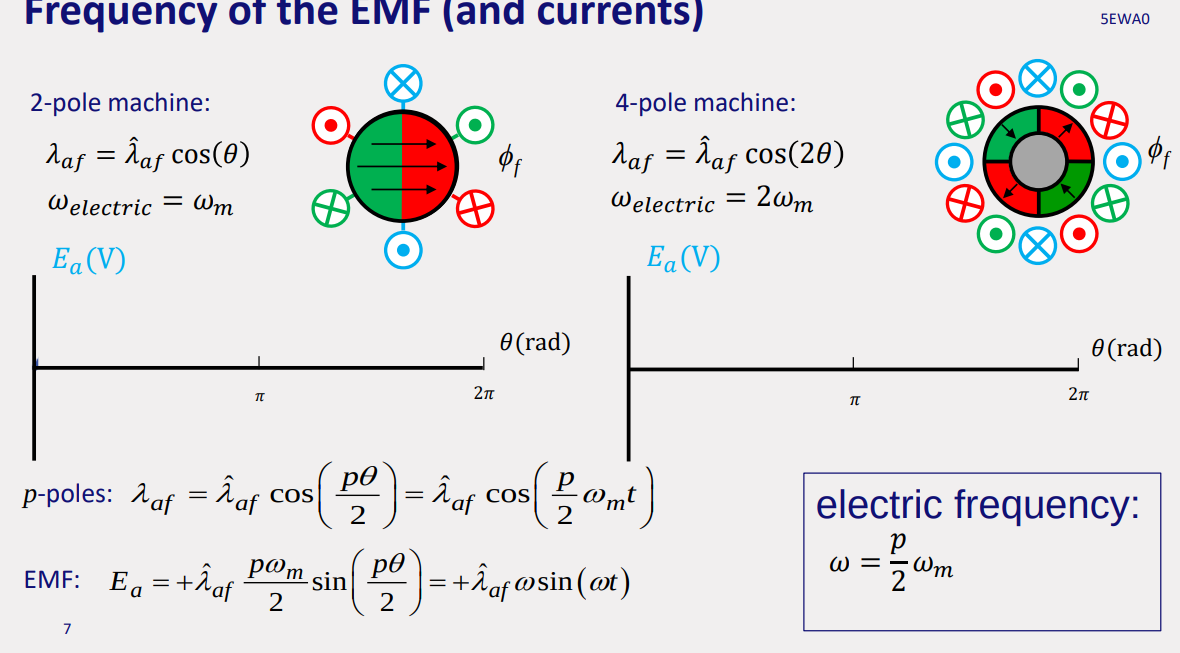
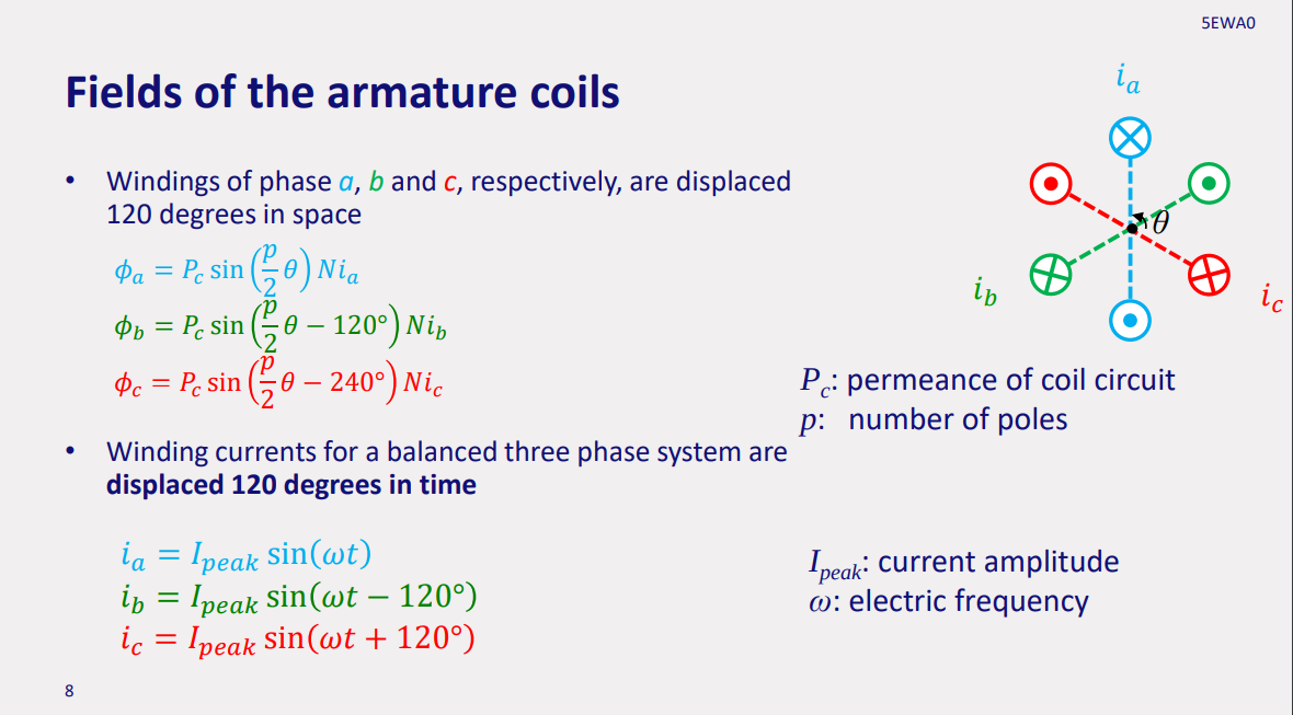
lag behind , - lead
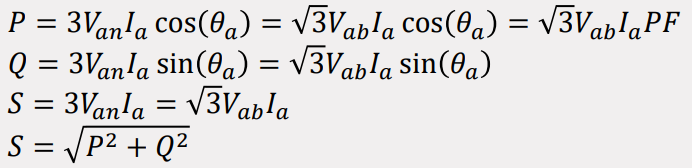
but since
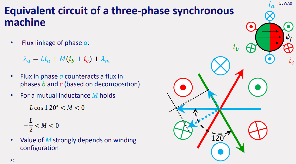
flux linkage affected by mutual inductance
IF
, lags behind
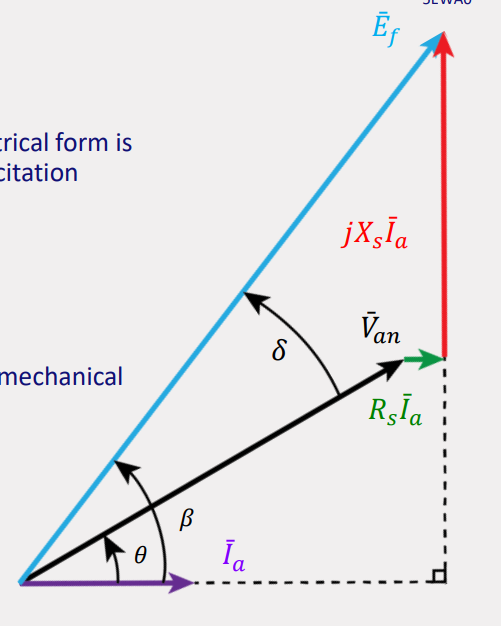
IF
or we can also say
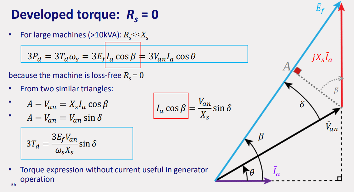
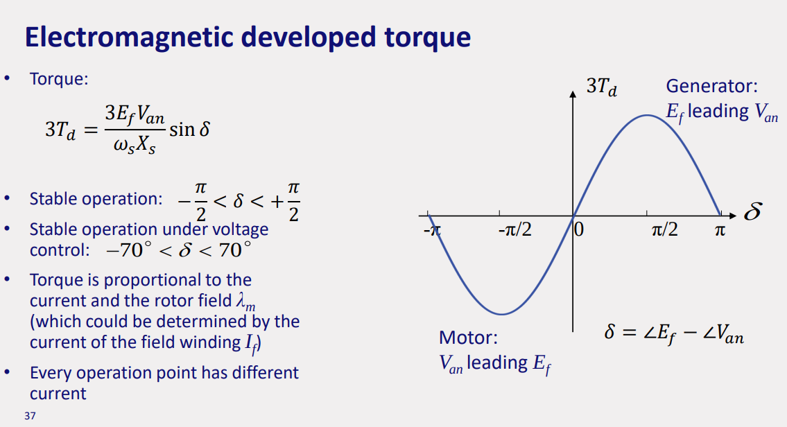
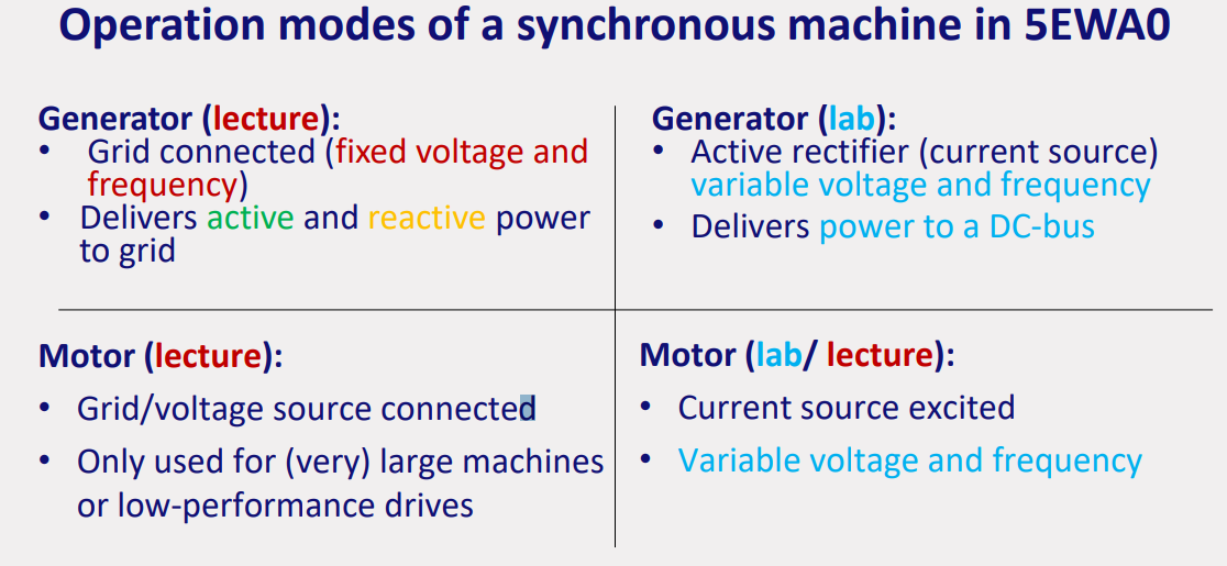
generator:
motor:
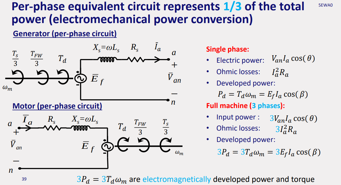
pf lagging ⇒
pf leading ⇒
pf unity ⇒
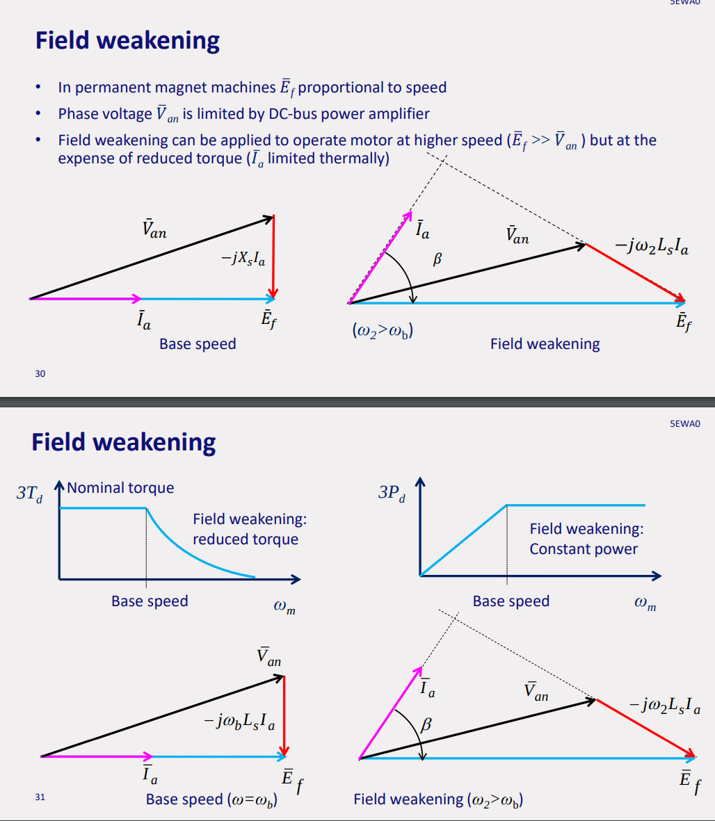
PHASOR REPRESENTATIONS

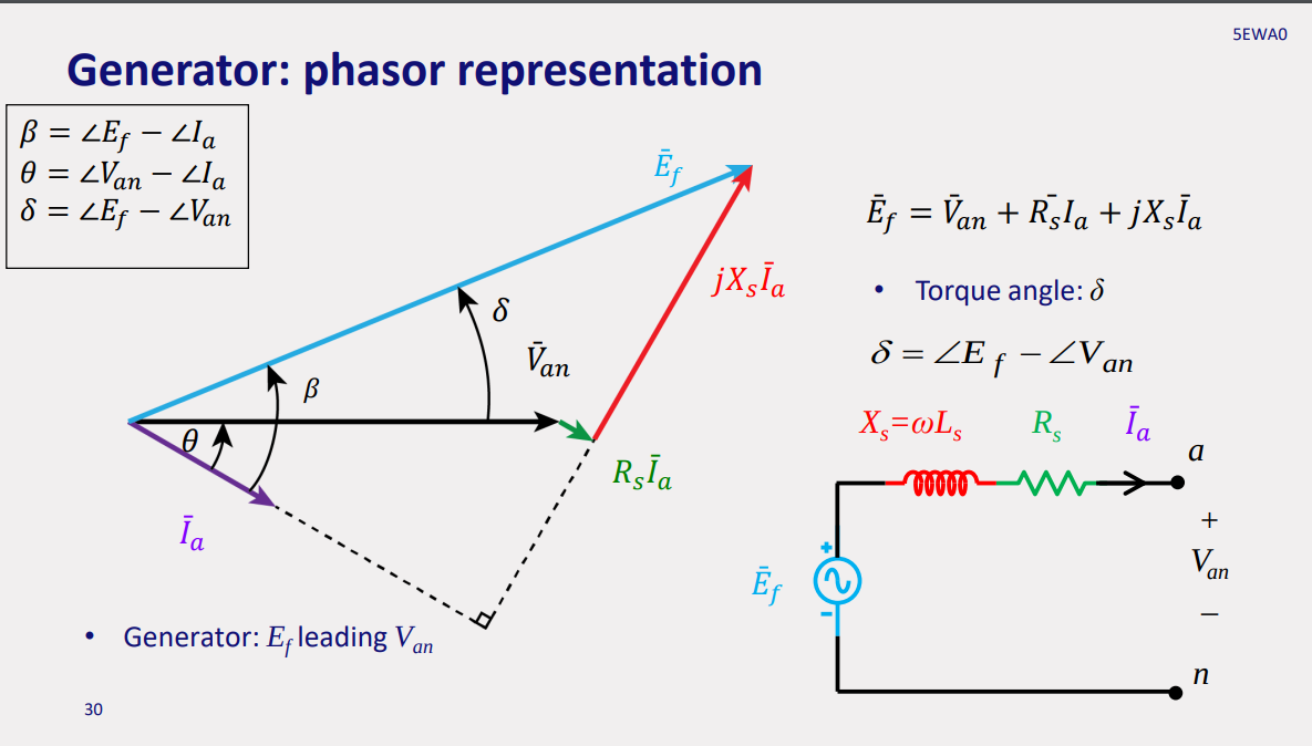
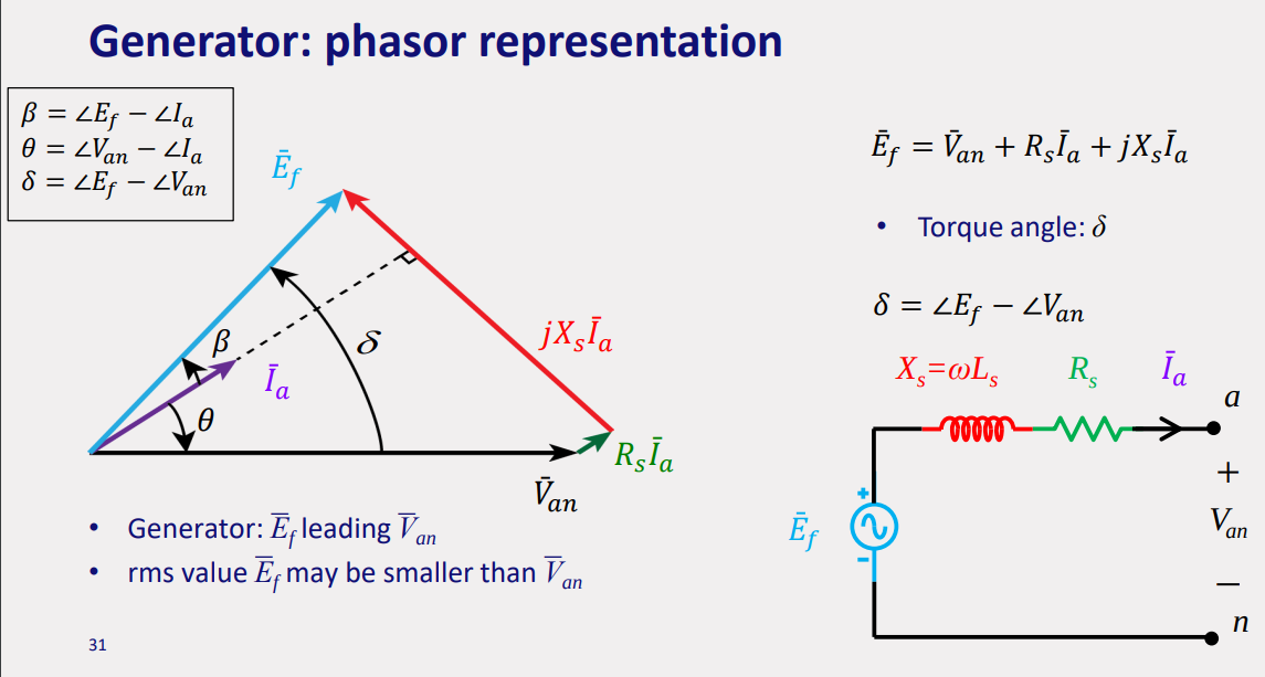
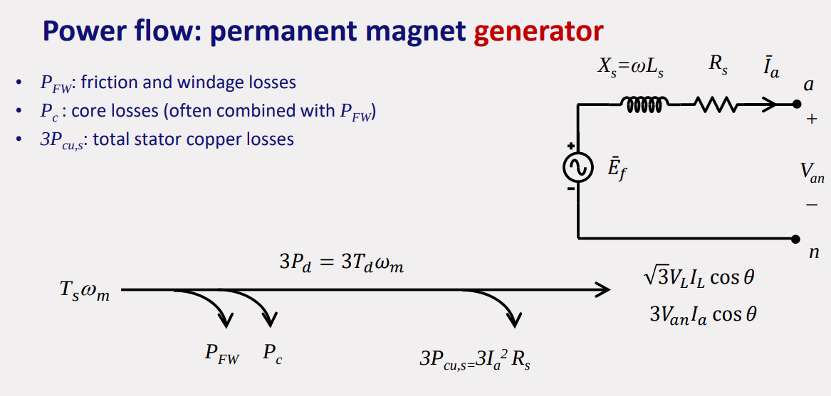
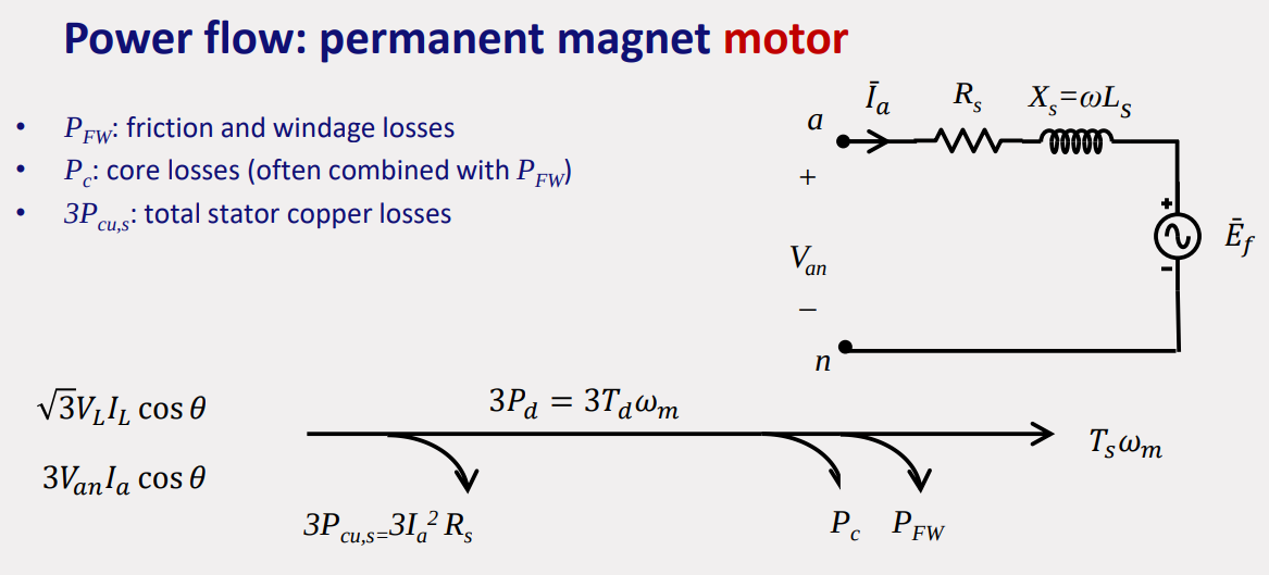
POWER FLOW
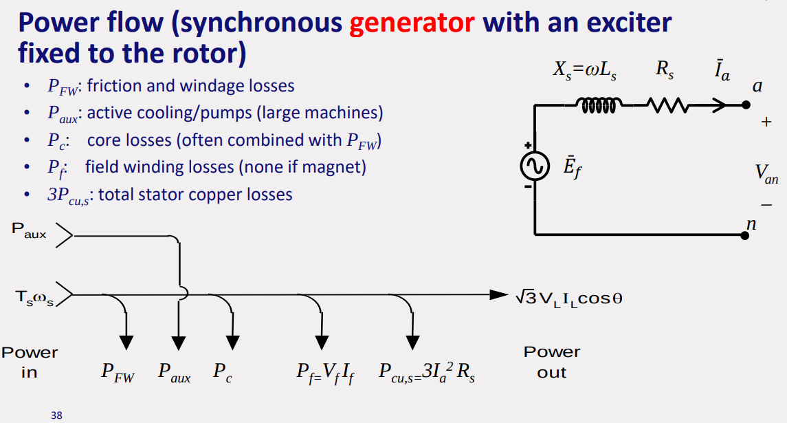
Isolated & Interconnected Generator
Induction Machines
Topics: Electric Machines · Three-Phase Power
General Theory
https://www.youtube.com/watch?v=AOC7uTnxmTI
https://www.electricaleasy.com/2015/06/difference-between-synchronous-and-induction-motor.html

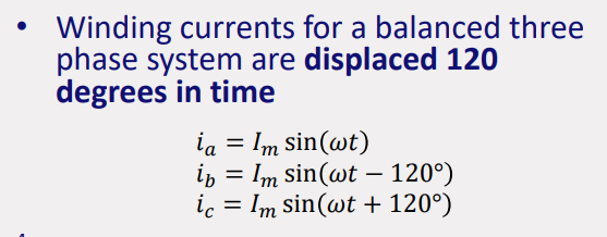
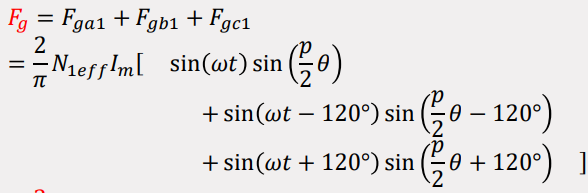
(total airgap mmf added together) total airgap mmf is a traveling or revolving wave:
(s-stator) (r-rotor)
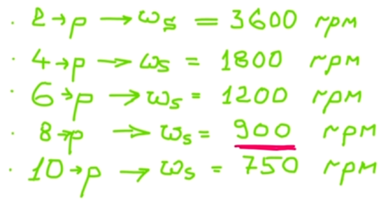
synchronous speed(speed of wave):
unlike synchronous machine
slip:
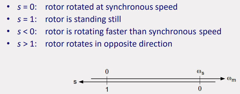
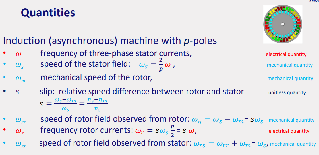
rotor induced voltages:- reference point on rotor
- mechanical speed difference with stator field (stator field passes rotor):
- p-pole field induces a voltage in the rotor winding with frequency:
- frequency of the rotor induced voltages:
speed of rotor relative to: - rotor:
→ speed difference between stator, rotor - stator:
→ have same speed - stator rotations field:
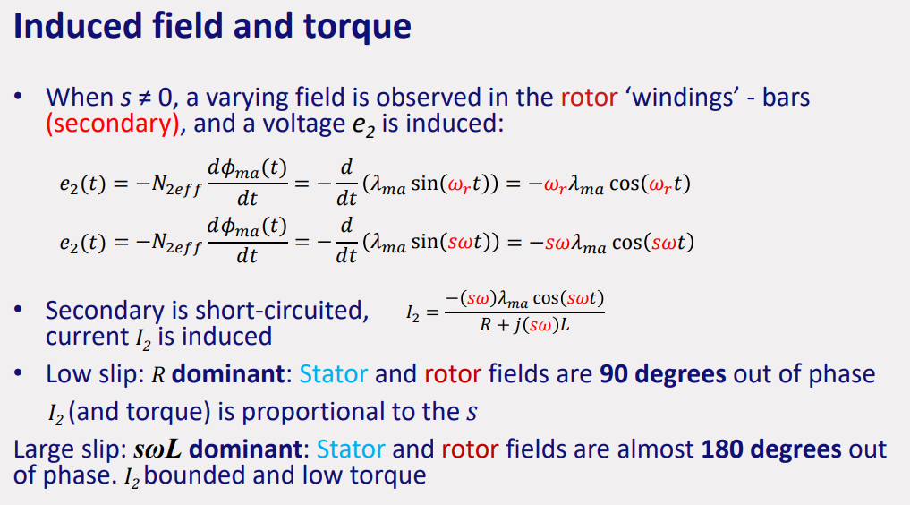
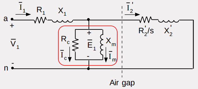
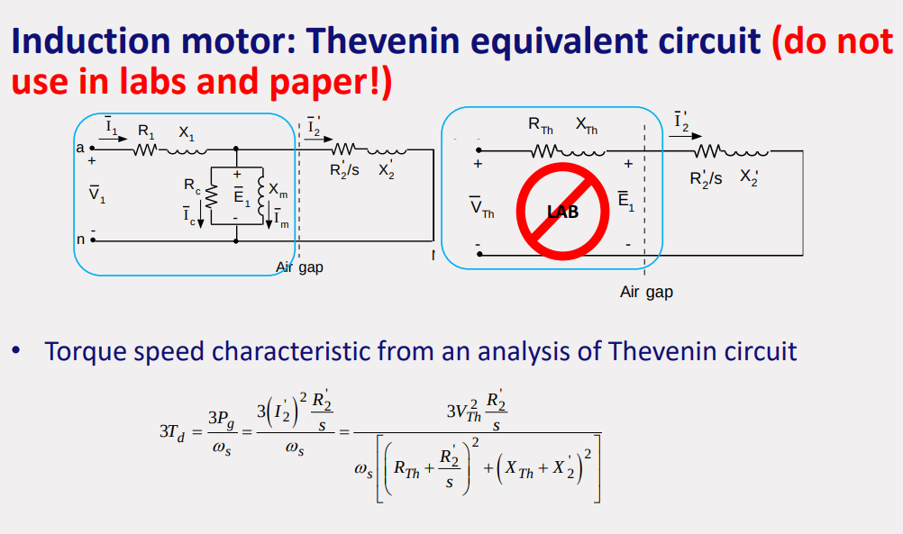
induction machine can be represented as a transformer:
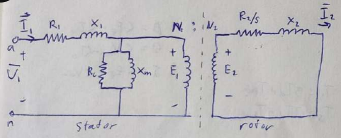
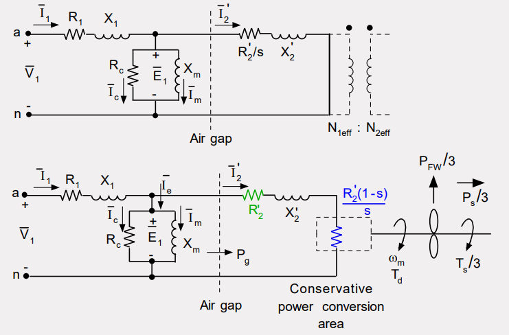
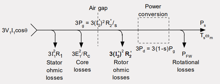
*if something comes after for instance after
if something comes before for instance before:
rotor ohmic losses:
core losses:
efficiency at point of operation
developed power (power supplied, rotational losses):
active power at terminals:
efficiency:
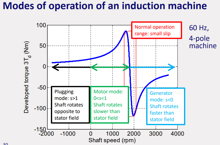
- Unstable for high slips: speed increase results in torque increase
- Stable operation for small slip: a speed increase results in a torque decrease
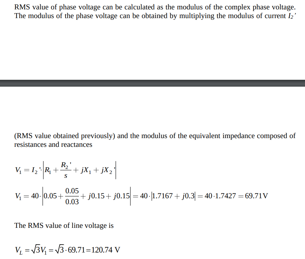
If the shaft speed is equal to the synchronous speed, the slip is zero, and there is no current flowing in the rotor. Therefore, the equivalent impedance seen from the terminals does not include the secondary side (as the rotor impedance is infinite due to zero slip)
Model Parameters
Blocked Rotor
Motor is excited with three-phase supply at rated rotor frequency and current (hence, requires reduced supply voltage and frequency)
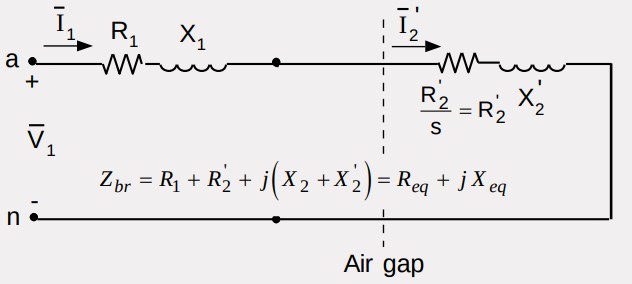
input current:
input voltage:
input power (per phase):
No-load Rotor
Motor is operated with rated voltage and frequency but without mechanical load
input voltage:
input current:
input power (per phase):
shaft speed:
Power supplied to secondary accounts for friction, windage and rotor ohmic losses:
Primary and secondary currents are determined:
active power balance:
reactive power balance:
the current is lagging the voltage due to inductive reactance
if we have the rated operating point slip:
Final Parameters
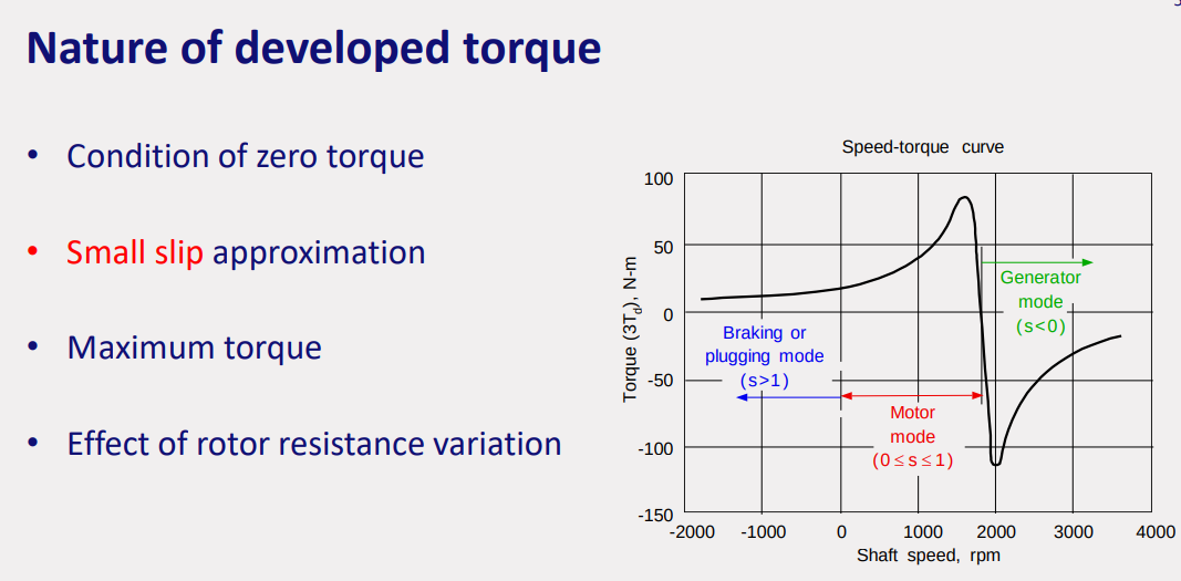
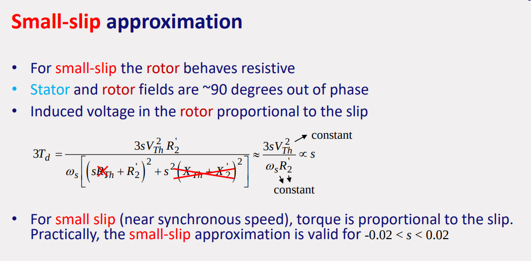
small slip approximation is only valid in that drop line in the graph, where speed and developed torque is proportional in manipulating the slip in that area of graph
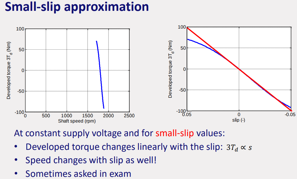
General unimportant
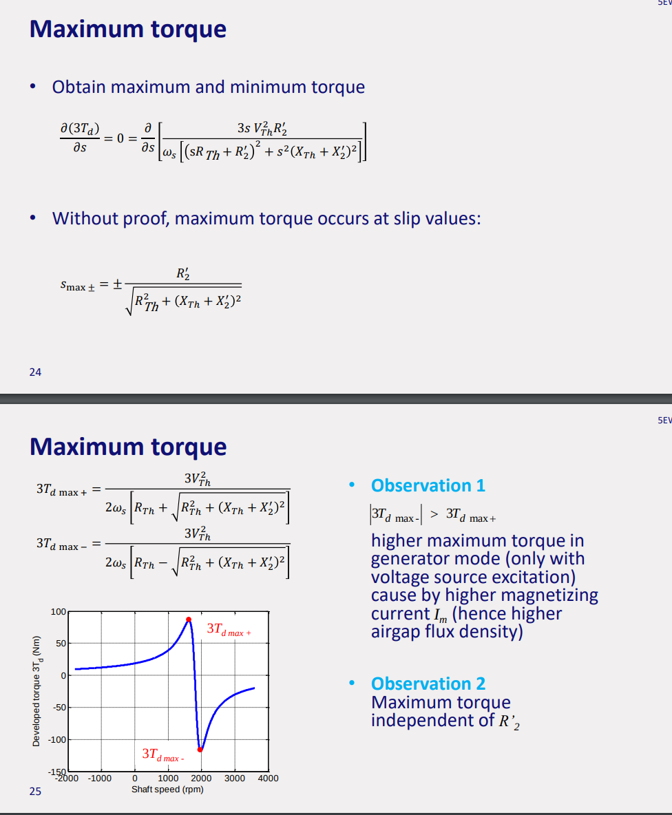
effects of rotor resistance: • Large
induction machine performance
- Maximum power coincides with maximum torque
- Plugging mode: no output power (all mechanical and electrical power is dissipated)
- Generator mode: power supplied to the shaft not always larger than power required for establishing stator field
- Induction machine is the single-excited (stator coils only)
- Power supply is required to produce the stator field
- Induction machine is only operating as a generator when more power on the shaft is supplied than required for producing the stator field
- Maximum efficiency at rated load • Low efficiency for small loads
- Maximum power factor at rated load • Low power factor for small loads
- • Starting current is often 5-6 times rated (nameplate) current
speed control
- Torque speed characteristic is anchored by the zero-crossing at the synchronous speed
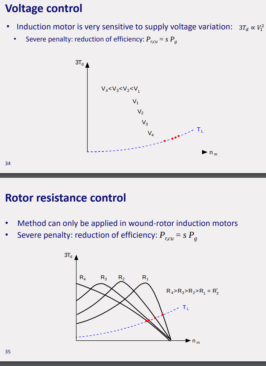
- Limited speed range: changing slope torque speed characteristics • Voltage control • Rotor resistance control
- Wide speed range • Frequency control
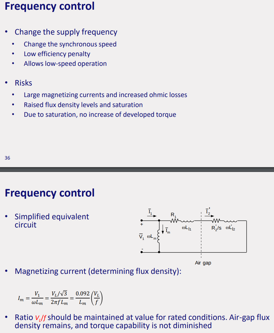
frequency control: • Both voltage and frequency have to be controlled • For same torque at lower supply frequency, the slip is larger, and hence, the efficiency lower • Efficiency for Ts=50 Nm indicated with circle