5EWB0 Electric Power Systems
- Area: Power and Energy
- Topics: Magnetic Circuits and Transformers · Electric Machines · Three-Phase Power
- Related courses: Electromechanics - 5EWA0
Content
Weekly Instruction Questions, intermediate test weeks 1-3, no cheat sheet
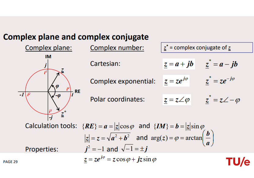
- Single phase complex calculations
- Calculations in balanced 3-phase systems, star & delta
- Generator and power-frequency control calculations
- Transformer calculations, cable and line calculations
- Network and power flow calculations
Week 1 and 2 - Basic principles
• Energy and power from electric and magnetic fields.
• Choices for transport of electrical energy: constant voltage, AC, sinusoidal, 50 Hz, 3-phases, high-voltage.
• The structure of the energy supply system: HV, medium voltage, low voltage network, house installation.
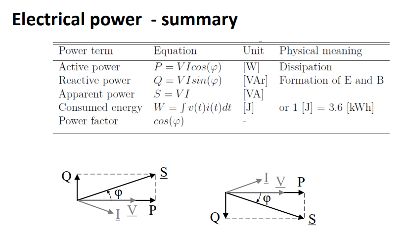
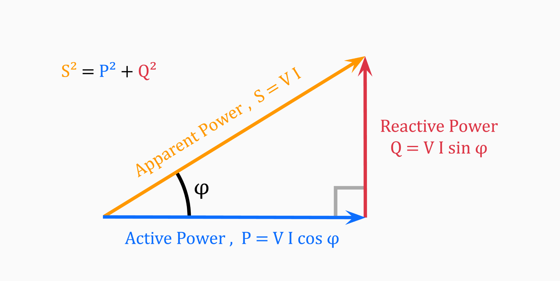
• Understanding of electrical power: active power P [W], reactive power Q [VAr], apparent power S [VA], complex power P+jQ, power factor (correction).
• Three-phase networks: advantages, line and phase voltage, power in 3-phases, per-phase analysis and Y-Δ transformations.
• Per-unit values .
Week 3 - Conventional generation and control of electrical power
• Understanding the operation of a synchronous generator, it’s single-phase equivalent circuit, the (maximal) power it can deliver, synchronous and (sub)transient reactance’s.
• Understanding the functioning of “automatic voltage control” and the control of reactive power generation.
• The principle of the power-frequency control of a power plant.
• The concept of economic dispatch of power plants.
• Understanding the concepts of conventional power generation
Week 4 - Components in electrical power systems
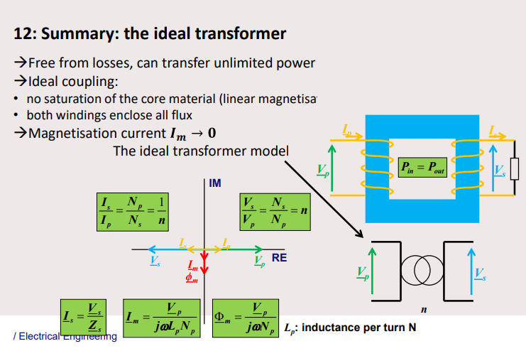
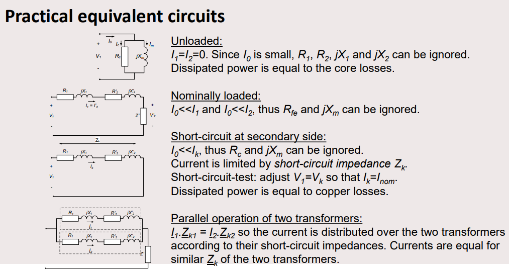
• Understanding of the principle of a transformer, its losses, its equivalent circuit in (un)loaded conditions.
• Understanding of how a transformer can be used for voltage and phase-angle control.
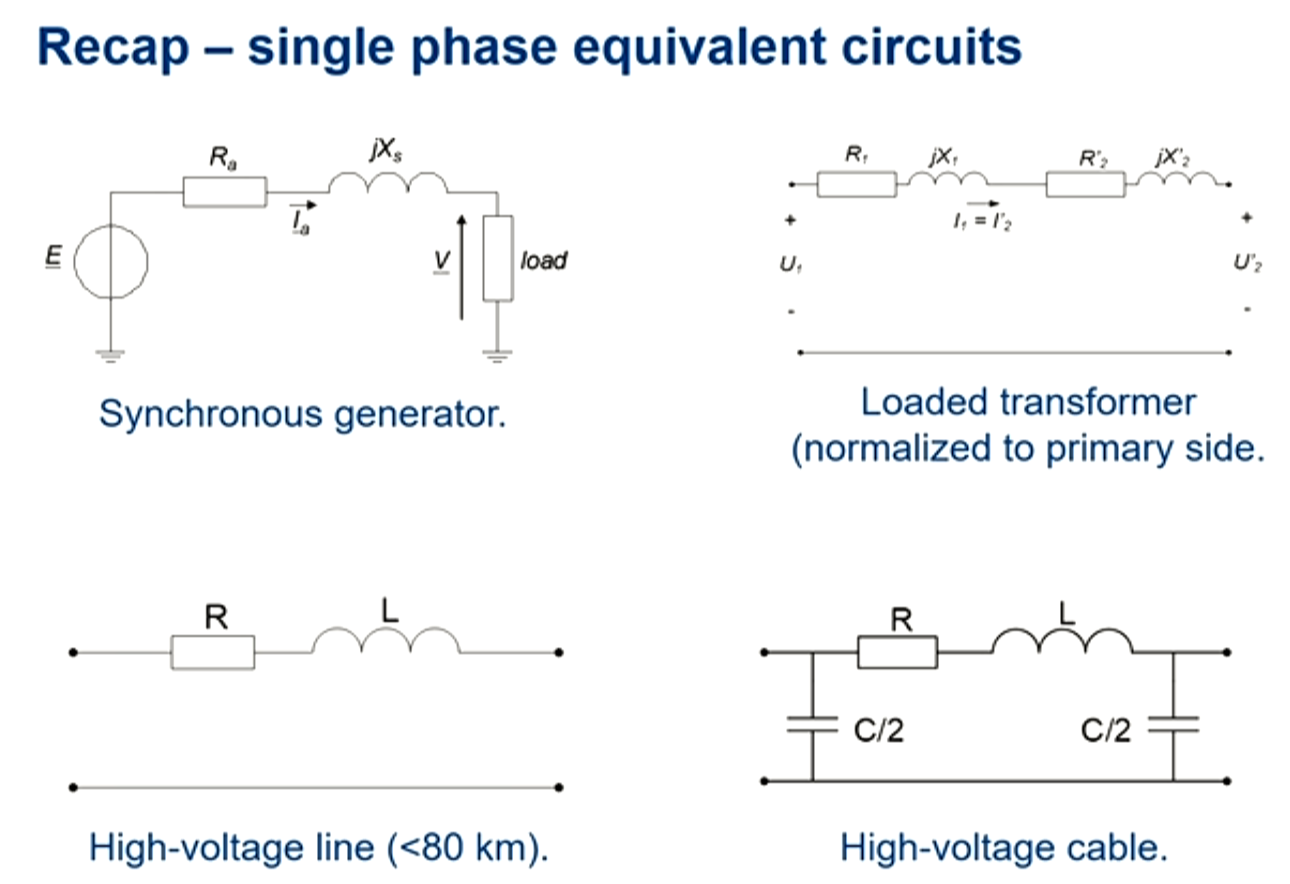
• Knowledge on the construction of lines and cables and their equivalent circuits.
• Understanding the lay-out of a high-voltage substation.
Week 5 and 6 - Network calculations and protection
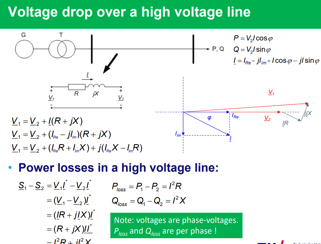
• Performing network calculations on voltage levels and transport losses.
• Understanding the effect of reactive power transport on network losses and voltage levels.
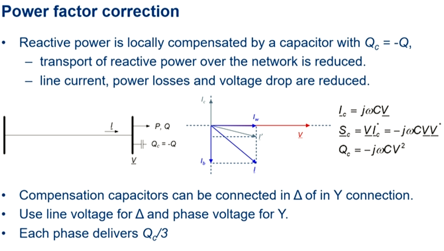
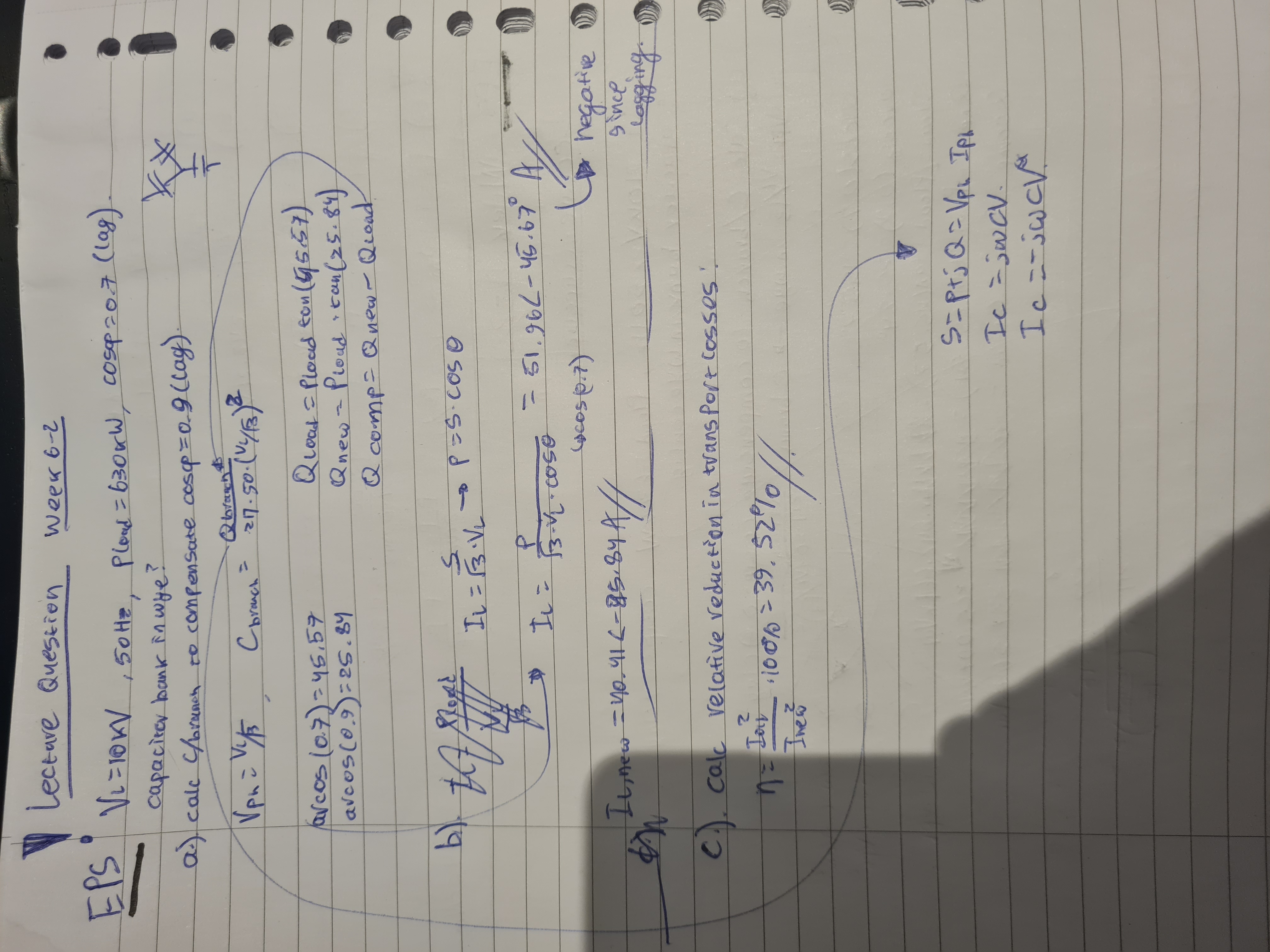
• Power factor correction.
• Methods for voltage regulation of power systems.
• Performing power flow calculations in power system networks (steady state analysis of a network).
• Understanding how to control power transfer in a power grid.
• Requirements for voltage stability of power systems.
• Understanding the causes, consequences and parameters of short circuits in power networks.
• Understanding how a power circuit breaker works.
Week 7 and 8 - Renewable generation of electricity
• Understanding the sustainability of electricity production.
• Electrical characteristics of photovoltaic and wind energy.
• Integration of renewables in the electricity grid: Distributed generation, technical problems (voltage stability, balancing, power quality), enabling technologies, example: electrical vehicles.
Basic principles
Topic: Three-Phase Power
Introduction
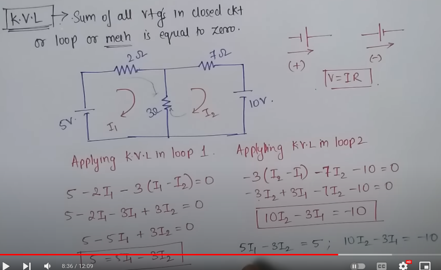
KVL: https://www.youtube.com/watch?v=qopLFbHdxjA
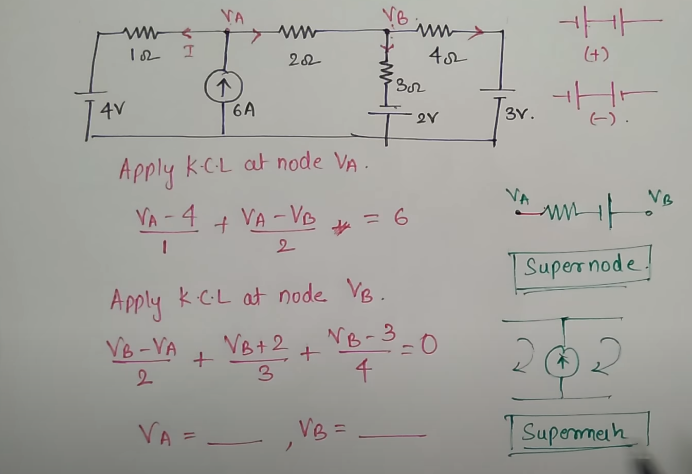
KCL: https://www.youtube.com/watch?v=g4HwMC0qU4g&t=199s
current through inductor → emf
Fundamentals
, , , , , , , ,
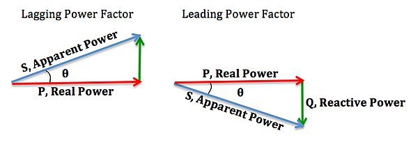
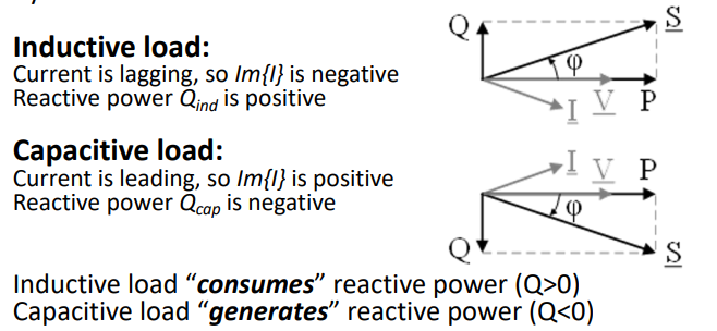
— →+ Negative, inject of power, & +→- Positive, dissipate powerReal power, also known as active power (P) is consumed by resistive loads. Reactive power (Q) is either consumed by inductive loads or generated by capacitive loads. Apparent power (S) is the capacity of your measured power system to provide real and reactive power.
Apparent(Total)=True(Beer)+Reactive(Foam) PowerKVL: Loop voltage, KCL: Point current
Magnitude Phasor:
RMS Value, effective value of AC system=DC:
Electrical Power
Analysis of a Series RL Circuit
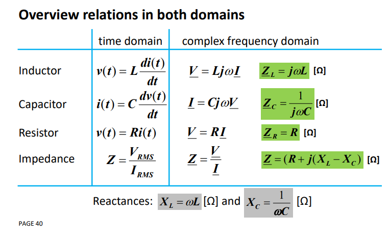
inductive reactance:
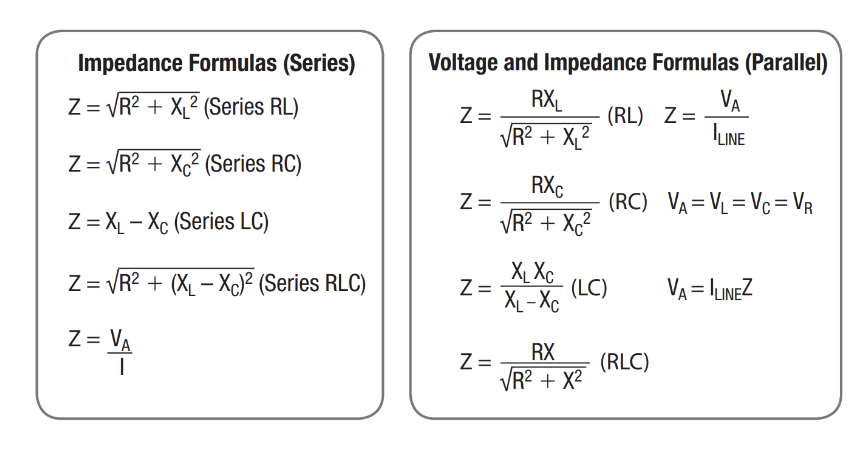
circuit impedance:
capacitive,inductive:
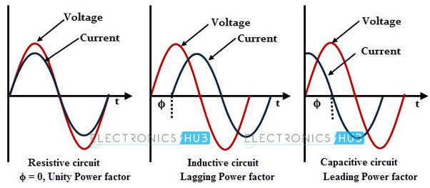
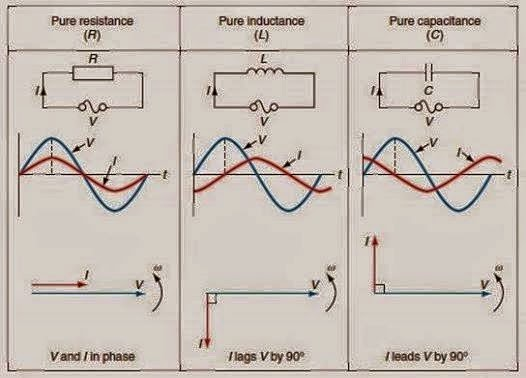
resistance:A positive phase angle would mean the current leads the voltage.
A negative phase angle means the current lags the voltage.The power factor (PF) is defined as the cosine of the angle (θ) between the apparent power and active power, which is given by:
Higher Better, Low: more inductive loads, higher , more Q, → Higher cost, system losses, cable diameter inc. Real/Active(usual, resistance):
Reactive(inductive, capacitive):
Apparent(sum):
⇒
Apparent Power:
NOTE
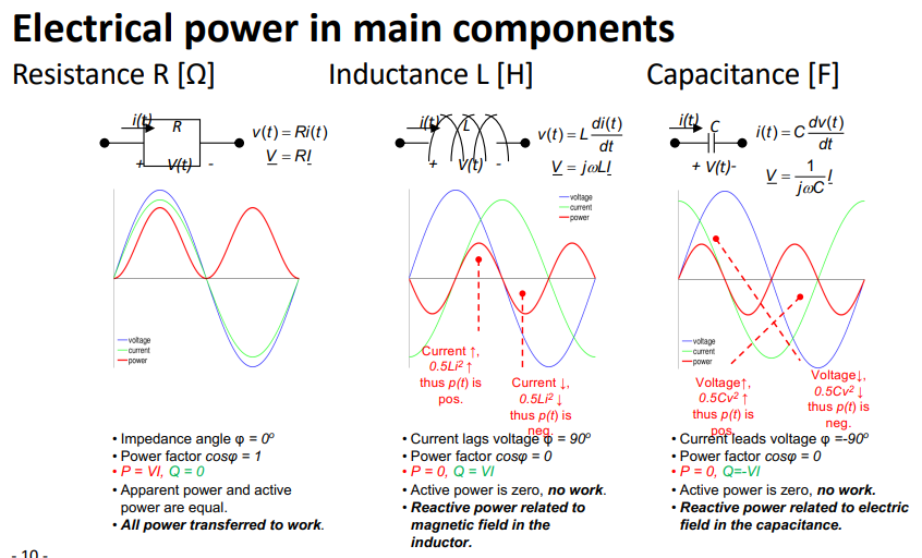
In electrical systems, there are two types of power: active and reactive. Active power does the actual work, like spinning a motor. Reactive power, however, doesn’t do any work but is necessary for the functioning of magnetic fields in inductive loads like motors.
Inductive loads, like motors, need reactive power to create magnetic fields, which is crucial for their operation. But, they absorb this reactive power from the grid, which can lead to inefficiencies and higher costs.
This is where capacitors come in. Capacitors provide a kind of reactive power that offsets the one absorbed by inductive loads. Think of it like a balance. On one side, you have inductive loads absorbing reactive power (making it positive), and on the other side, you have capacitors supplying it (making it negative). By balancing these two, the overall demand for reactive power from the grid is reduced, leading to a more efficient and cost-effective system.
So, capacitors are used to “compensate” or balance out the reactive power in the system, making it more efficient.
Balanced Systems, D/Y Transformations & Per Unit System
3 Phase Network: https://www.youtube.com/watch?v=quABfe4Ev3s
3 Phase System
increase transported capacity by combining multiple systems in such a way that the total current in one of the conductors becomes zero and so that the total power losses are minimal. balanced:
degrees out of phase. - equal in magnitude
- phases in order, counter-clockwise→
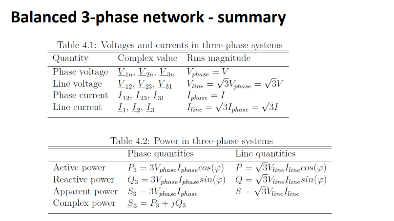
Line voltage is the voltage measured between any two lines in a three-phase circuit. Phase voltage is the voltage measured across a single component in a three-phase source or load.
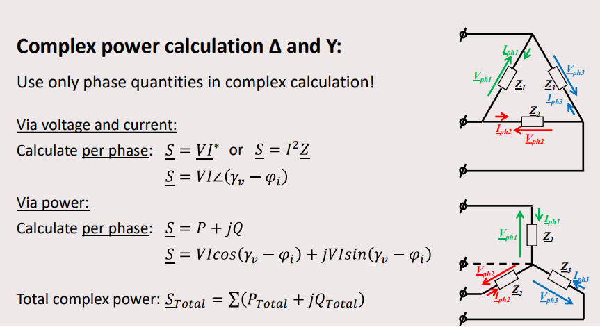
Apparent Power:Balanced Star/wye (Y) - use KVL:
,
Balanced Delta - use KCL:, you cant add apparant powers instead add complex powers
(via power)
(via V|I)
in a balanced system:
- (via power)
- (via V|I)
Apparent power per phase using:
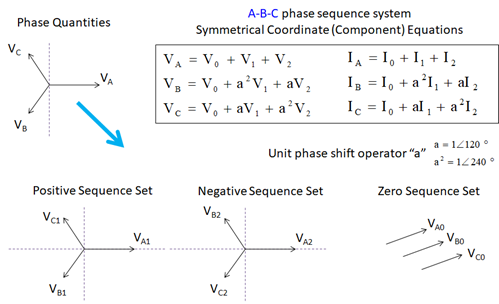
Phase Quantities:
Line Quantities:current lags/leads ⇒ power lags/leads
compensation:
Working in phase domain: (Y-config), Working in line domain: (
-config) Y → the impedance are equal on each branch
→ the impedance are split equally on each branch
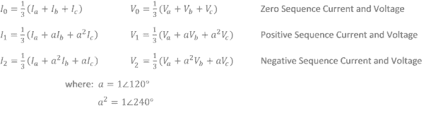
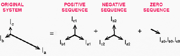
original system=unbalanced system
Conventional generation & control of electrical power
Topic: Electric Machines
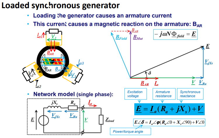
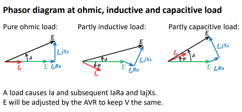
- An alternator or synchronous generator works on the principle of electromagnetic induction, i.e., when the flux linking a conductor changes, an EMF is induced in the conductor. When the armature winding of alternator subjected to the rotating magnetic field, the voltage will be generated in the armature winding.
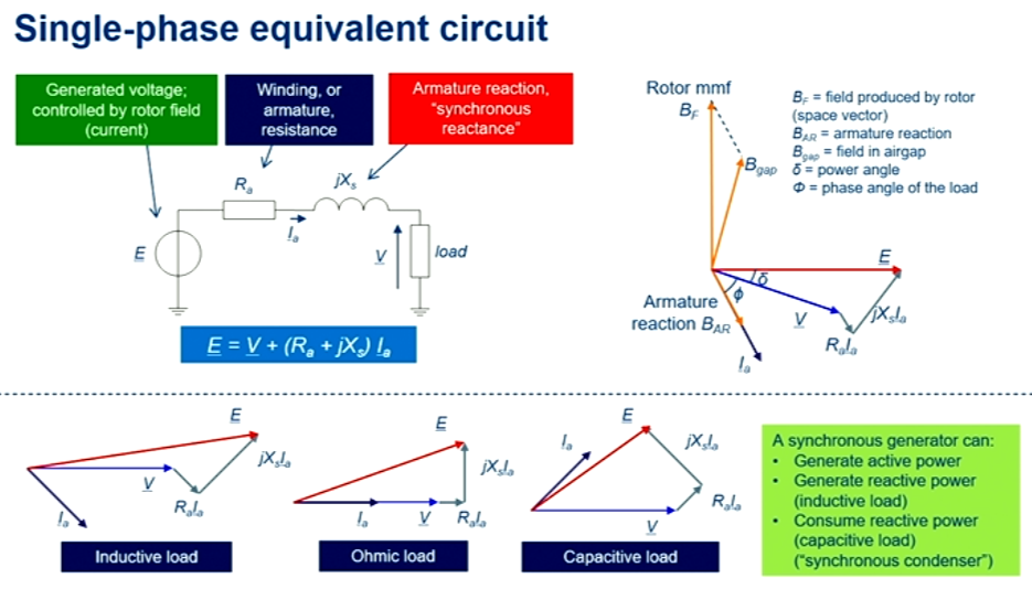
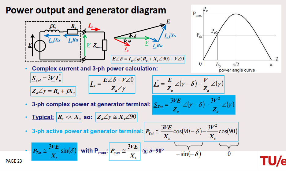
max power of synchronous generator:
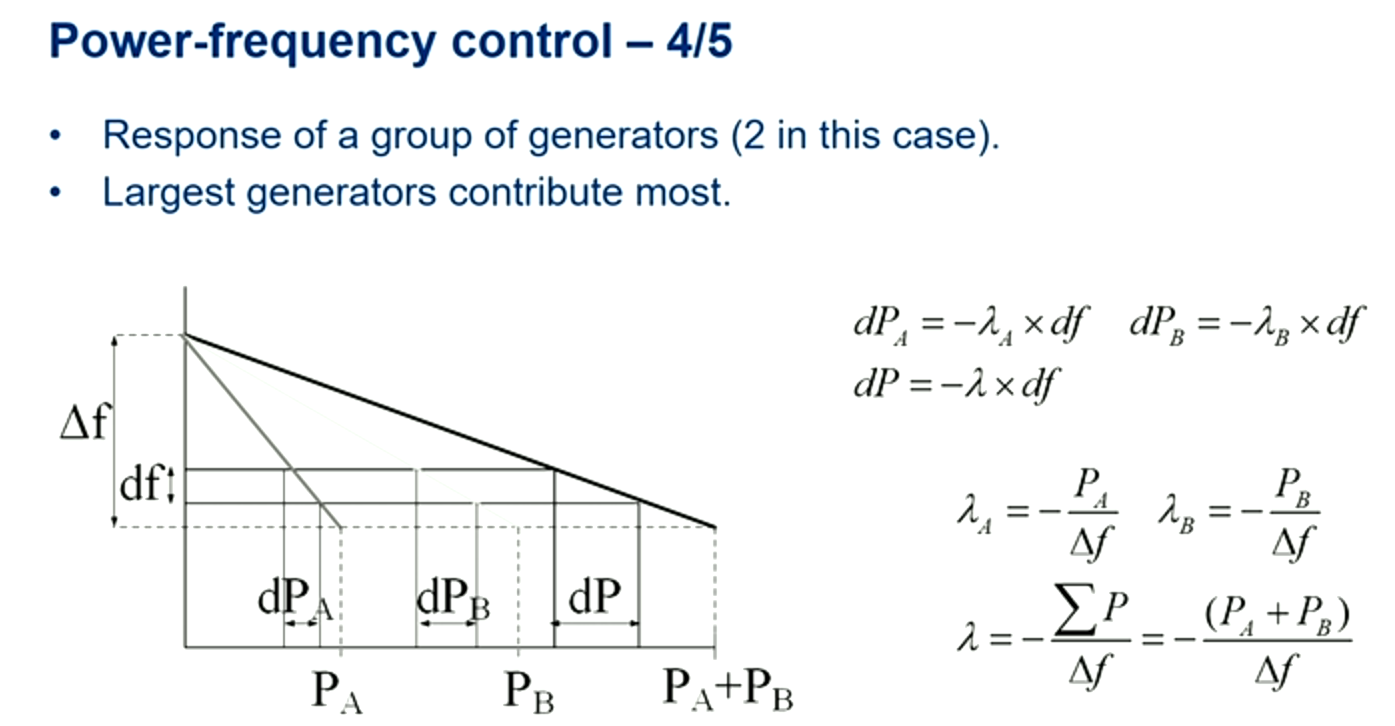
power frequency control: control of active power and frequency
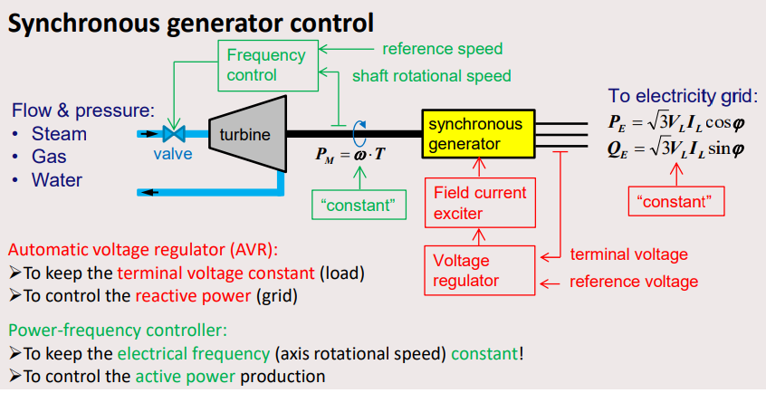
controlling reactive power(Q): AVR (automatic voltage regulator), varies (E)
controlling active power(P): Power-frequency control (inversely proportional), (speed up generator less power)
Synchronous Generator
alternating induction voltage:
or where p: number of poles, P: number of pole pairs, f: frequency, n: num of revolutions
Mechanical rotational power(T:tension):
unloaded synchronous generator:
controlled by AVR
Power Output Derivation
complex current and 3-ph power calculation:
,
rearrange theformula:
so:
If at terminal: () where
Components in electrical power systems
Topics: Magnetic Circuits and Transformers · Three-Phase Power
Lenz law:
skin effect:
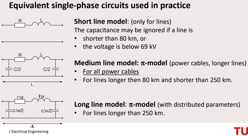
Underground cables currently have a limited voltage capacity and cannot carry more than 66kv. In contrast, overhead power lines can handle more than 400kv, making them ideal for serving high-energy needs such as industrial applications.
overhead lines:
, , ,
short line model:
The reactive power of the connection always exists
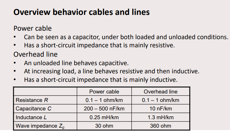
Power cables :
1 Can be seen as a capacitor, under both loaded and unloaded conditions.
2 Have a short circuit impedance that is mainly resistive.
Overhead lines :
1 An unloaded line behaves capacitive.
2 At increasing load, a line behaves resistive, and then inductive.
3 Their short circuit impedance is mainly inductive.
Transformer
eddy current losses:
hysteresis losses:
Coil 1 is normally in delta connection, coil 2 in star connection.
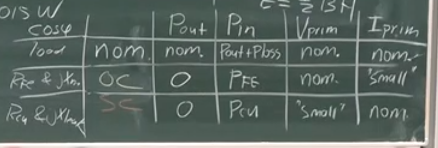
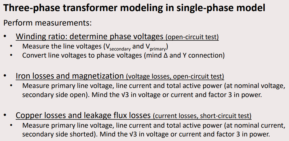
Zero load = iron losses = secondary nominal voltage, primary side open circuit.
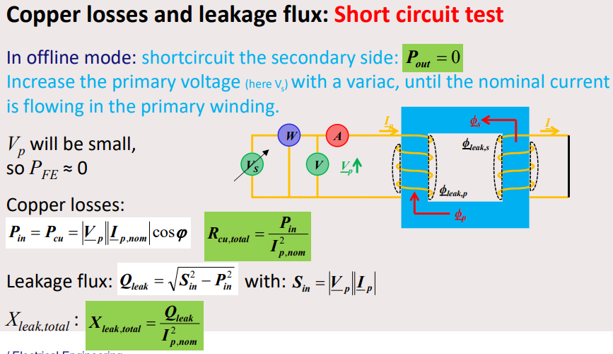
Copper losses are primary side short circuited , secondary side lower voltage.
Short Circuit = Copper Loss = Given Power loss. At no load measure the iron losses, under short circuit the conductor losses.
Disadvantages transformer is saturated B-H curve, Hysteresis losses, Eddy Current losses.
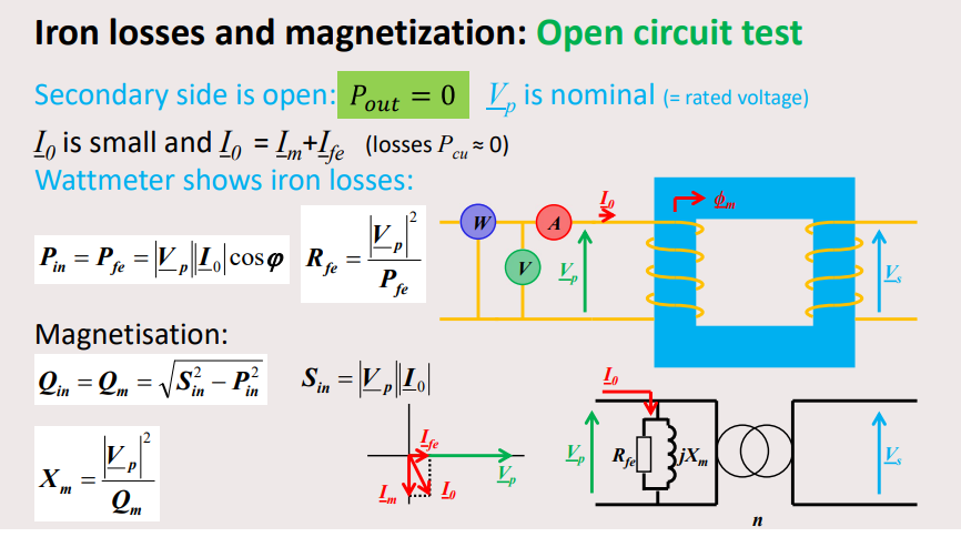
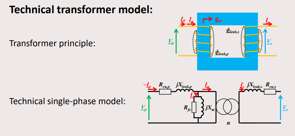
Zero Load Losses =
transformer maintenance: oil checking etc…
transformer (re-)energization: power quality, inrush current, transient Vrms drop etc…
transformers failure: insulation failure, hazard function etc…
transformers in smart grids: better security, pollution reduce etc…
Network calculations and protection
remedies to consume less reactive power: limit power factor:
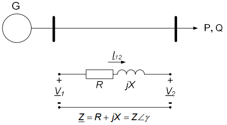
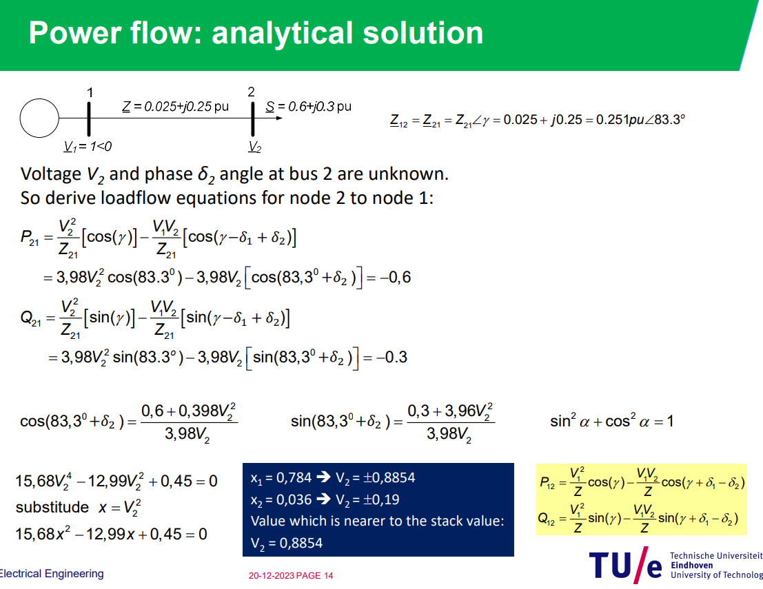
Load flow calculations are used to determine the voltage, current, and real and reactive power at various points in a power system under normal steady-state conditions.
- Transient faults - Do not damage insulation permanently
Circuit Breakers
- Disconnecter can only switch under the absence of current. Circuit breaker must be able to interrupt short circuit current as well (up to 80 kA).
- Breakdown will occur at weakest location an ”arc” will start until the magnetic energy will have been dissipated. The arc will not stop before
Power losses in high voltage line:
single phase:
voltages are phase-voltages,
Power Flow
or
therefor (or do times 3):
direction of flow of power→sign
Per unit system
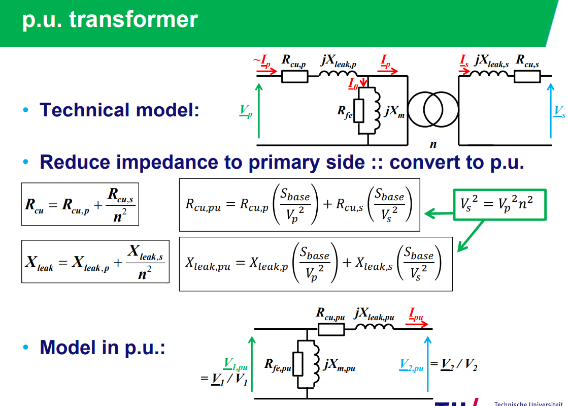
only magnitudes are scaled while phase angles are the same
allows for interconnection of power systems with different voltage levels
normal phasor quantities:, , ,
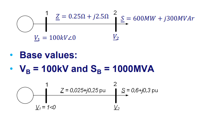
base values:and and
p.u. quantities:, , ,
WITH ASYNCHRONOUS GENERATOR YOU CAN CONTROL
remember the power flow example:
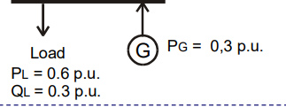
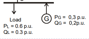
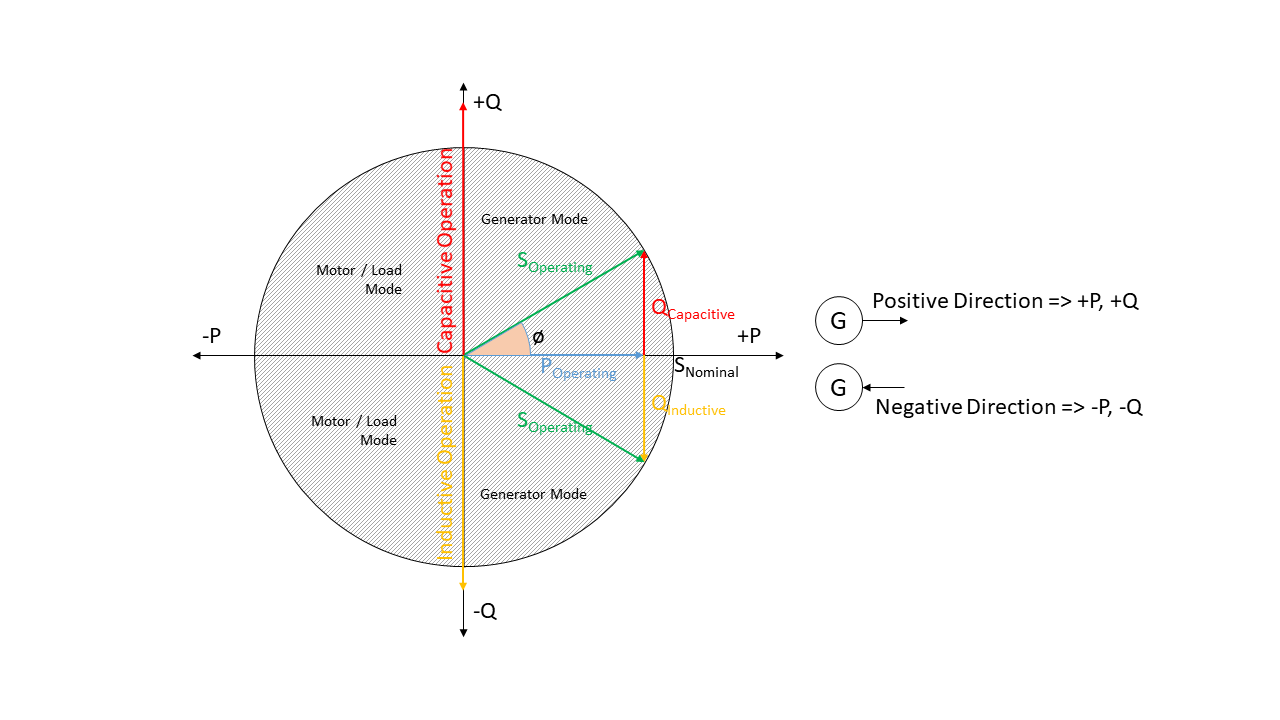
async generator always needs reactive power as it is connected to the grid.
while sync connected to grid directly which can control the voltage so only needs
smaller current → larger voltage as less power drop over transport line since you generate more → in positive capacitive load case
Renewable generation of electricity
RES: Renewable Energy Share
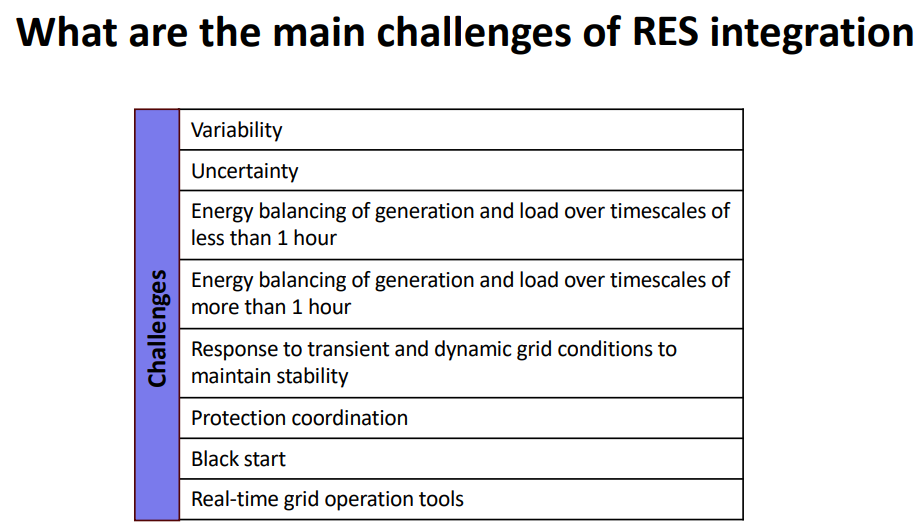
details on slides week 7
Wind energy is depended on: